EP4239351B1 - Utilisation de paramètres de système de batterie pour estimer l'espérance de vie de batterie dans des véhicules électriques et hybrides électriques - Google Patents
Utilisation de paramètres de système de batterie pour estimer l'espérance de vie de batterie dans des véhicules électriques et hybrides électriques Download PDFInfo
- Publication number
- EP4239351B1 EP4239351B1 EP22203429.0A EP22203429A EP4239351B1 EP 4239351 B1 EP4239351 B1 EP 4239351B1 EP 22203429 A EP22203429 A EP 22203429A EP 4239351 B1 EP4239351 B1 EP 4239351B1
- Authority
- EP
- European Patent Office
- Prior art keywords
- battery
- value
- rul
- estimated
- estimate
- Prior art date
- Legal status (The legal status is an assumption and is not a legal conclusion. Google has not performed a legal analysis and makes no representation as to the accuracy of the status listed.)
- Active
Links
Images






Classifications
-
- B—PERFORMING OPERATIONS; TRANSPORTING
- B60—VEHICLES IN GENERAL
- B60L—PROPULSION OF ELECTRICALLY-PROPELLED VEHICLES; SUPPLYING ELECTRIC POWER FOR AUXILIARY EQUIPMENT OF ELECTRICALLY-PROPELLED VEHICLES; ELECTRODYNAMIC BRAKE SYSTEMS FOR VEHICLES IN GENERAL; MAGNETIC SUSPENSION OR LEVITATION FOR VEHICLES; MONITORING OPERATING VARIABLES OF ELECTRICALLY-PROPELLED VEHICLES; ELECTRIC SAFETY DEVICES FOR ELECTRICALLY-PROPELLED VEHICLES
- B60L3/00—Electric devices on electrically-propelled vehicles for safety purposes; Monitoring operating variables, e.g. speed, deceleration or energy consumption
- B60L3/12—Recording operating variables ; Monitoring of operating variables
-
- B—PERFORMING OPERATIONS; TRANSPORTING
- B60—VEHICLES IN GENERAL
- B60L—PROPULSION OF ELECTRICALLY-PROPELLED VEHICLES; SUPPLYING ELECTRIC POWER FOR AUXILIARY EQUIPMENT OF ELECTRICALLY-PROPELLED VEHICLES; ELECTRODYNAMIC BRAKE SYSTEMS FOR VEHICLES IN GENERAL; MAGNETIC SUSPENSION OR LEVITATION FOR VEHICLES; MONITORING OPERATING VARIABLES OF ELECTRICALLY-PROPELLED VEHICLES; ELECTRIC SAFETY DEVICES FOR ELECTRICALLY-PROPELLED VEHICLES
- B60L58/00—Methods or circuit arrangements for monitoring or controlling batteries or fuel cells, specially adapted for electric vehicles
- B60L58/10—Methods or circuit arrangements for monitoring or controlling batteries or fuel cells, specially adapted for electric vehicles for monitoring or controlling batteries
- B60L58/12—Methods or circuit arrangements for monitoring or controlling batteries or fuel cells, specially adapted for electric vehicles for monitoring or controlling batteries responding to state of charge [SoC]
-
- B—PERFORMING OPERATIONS; TRANSPORTING
- B60—VEHICLES IN GENERAL
- B60L—PROPULSION OF ELECTRICALLY-PROPELLED VEHICLES; SUPPLYING ELECTRIC POWER FOR AUXILIARY EQUIPMENT OF ELECTRICALLY-PROPELLED VEHICLES; ELECTRODYNAMIC BRAKE SYSTEMS FOR VEHICLES IN GENERAL; MAGNETIC SUSPENSION OR LEVITATION FOR VEHICLES; MONITORING OPERATING VARIABLES OF ELECTRICALLY-PROPELLED VEHICLES; ELECTRIC SAFETY DEVICES FOR ELECTRICALLY-PROPELLED VEHICLES
- B60L58/00—Methods or circuit arrangements for monitoring or controlling batteries or fuel cells, specially adapted for electric vehicles
- B60L58/10—Methods or circuit arrangements for monitoring or controlling batteries or fuel cells, specially adapted for electric vehicles for monitoring or controlling batteries
- B60L58/16—Methods or circuit arrangements for monitoring or controlling batteries or fuel cells, specially adapted for electric vehicles for monitoring or controlling batteries responding to battery ageing, e.g. to the number of charging cycles or the state of health [SoH]
-
- G—PHYSICS
- G01—MEASURING; TESTING
- G01R—MEASURING ELECTRIC VARIABLES; MEASURING MAGNETIC VARIABLES
- G01R31/00—Arrangements for testing electric properties; Arrangements for locating electric faults; Arrangements for electrical testing characterised by what is being tested not provided for elsewhere
- G01R31/36—Arrangements for testing, measuring or monitoring the electrical condition of accumulators or electric batteries, e.g. capacity or state of charge [SoC]
- G01R31/367—Software therefor, e.g. for battery testing using modelling or look-up tables
-
- G—PHYSICS
- G01—MEASURING; TESTING
- G01R—MEASURING ELECTRIC VARIABLES; MEASURING MAGNETIC VARIABLES
- G01R31/00—Arrangements for testing electric properties; Arrangements for locating electric faults; Arrangements for electrical testing characterised by what is being tested not provided for elsewhere
- G01R31/36—Arrangements for testing, measuring or monitoring the electrical condition of accumulators or electric batteries, e.g. capacity or state of charge [SoC]
- G01R31/382—Arrangements for monitoring battery or accumulator variables, e.g. SoC
-
- G—PHYSICS
- G01—MEASURING; TESTING
- G01R—MEASURING ELECTRIC VARIABLES; MEASURING MAGNETIC VARIABLES
- G01R31/00—Arrangements for testing electric properties; Arrangements for locating electric faults; Arrangements for electrical testing characterised by what is being tested not provided for elsewhere
- G01R31/36—Arrangements for testing, measuring or monitoring the electrical condition of accumulators or electric batteries, e.g. capacity or state of charge [SoC]
- G01R31/382—Arrangements for monitoring battery or accumulator variables, e.g. SoC
- G01R31/3842—Arrangements for monitoring battery or accumulator variables, e.g. SoC combining voltage and current measurements
-
- G—PHYSICS
- G01—MEASURING; TESTING
- G01R—MEASURING ELECTRIC VARIABLES; MEASURING MAGNETIC VARIABLES
- G01R31/00—Arrangements for testing electric properties; Arrangements for locating electric faults; Arrangements for electrical testing characterised by what is being tested not provided for elsewhere
- G01R31/36—Arrangements for testing, measuring or monitoring the electrical condition of accumulators or electric batteries, e.g. capacity or state of charge [SoC]
- G01R31/392—Determining battery ageing or deterioration, e.g. state of health
-
- G—PHYSICS
- G01—MEASURING; TESTING
- G01R—MEASURING ELECTRIC VARIABLES; MEASURING MAGNETIC VARIABLES
- G01R31/00—Arrangements for testing electric properties; Arrangements for locating electric faults; Arrangements for electrical testing characterised by what is being tested not provided for elsewhere
- G01R31/36—Arrangements for testing, measuring or monitoring the electrical condition of accumulators or electric batteries, e.g. capacity or state of charge [SoC]
- G01R31/396—Acquisition or processing of data for testing or for monitoring individual cells or groups of cells within a battery
-
- G—PHYSICS
- G07—CHECKING-DEVICES
- G07C—TIME OR ATTENDANCE REGISTERS; REGISTERING OR INDICATING THE WORKING OF MACHINES; GENERATING RANDOM NUMBERS; VOTING OR LOTTERY APPARATUS; ARRANGEMENTS, SYSTEMS OR APPARATUS FOR CHECKING NOT PROVIDED FOR ELSEWHERE
- G07C5/00—Registering or indicating the working of vehicles
- G07C5/004—Indicating the operating range of the engine
-
- H—ELECTRICITY
- H01—ELECTRIC ELEMENTS
- H01M—PROCESSES OR MEANS, e.g. BATTERIES, FOR THE DIRECT CONVERSION OF CHEMICAL ENERGY INTO ELECTRICAL ENERGY
- H01M10/00—Secondary cells; Manufacture thereof
- H01M10/42—Methods or arrangements for servicing or maintenance of secondary cells or secondary half-cells
- H01M10/48—Accumulators combined with arrangements for measuring, testing or indicating the condition of cells, e.g. the level or density of the electrolyte
- H01M10/486—Accumulators combined with arrangements for measuring, testing or indicating the condition of cells, e.g. the level or density of the electrolyte for measuring temperature
-
- B—PERFORMING OPERATIONS; TRANSPORTING
- B60—VEHICLES IN GENERAL
- B60L—PROPULSION OF ELECTRICALLY-PROPELLED VEHICLES; SUPPLYING ELECTRIC POWER FOR AUXILIARY EQUIPMENT OF ELECTRICALLY-PROPELLED VEHICLES; ELECTRODYNAMIC BRAKE SYSTEMS FOR VEHICLES IN GENERAL; MAGNETIC SUSPENSION OR LEVITATION FOR VEHICLES; MONITORING OPERATING VARIABLES OF ELECTRICALLY-PROPELLED VEHICLES; ELECTRIC SAFETY DEVICES FOR ELECTRICALLY-PROPELLED VEHICLES
- B60L2240/00—Control parameters of input or output; Target parameters
- B60L2240/40—Drive Train control parameters
- B60L2240/54—Drive Train control parameters related to batteries
- B60L2240/545—Temperature
-
- B—PERFORMING OPERATIONS; TRANSPORTING
- B60—VEHICLES IN GENERAL
- B60L—PROPULSION OF ELECTRICALLY-PROPELLED VEHICLES; SUPPLYING ELECTRIC POWER FOR AUXILIARY EQUIPMENT OF ELECTRICALLY-PROPELLED VEHICLES; ELECTRODYNAMIC BRAKE SYSTEMS FOR VEHICLES IN GENERAL; MAGNETIC SUSPENSION OR LEVITATION FOR VEHICLES; MONITORING OPERATING VARIABLES OF ELECTRICALLY-PROPELLED VEHICLES; ELECTRIC SAFETY DEVICES FOR ELECTRICALLY-PROPELLED VEHICLES
- B60L2240/00—Control parameters of input or output; Target parameters
- B60L2240/40—Drive Train control parameters
- B60L2240/54—Drive Train control parameters related to batteries
- B60L2240/547—Voltage
-
- B—PERFORMING OPERATIONS; TRANSPORTING
- B60—VEHICLES IN GENERAL
- B60L—PROPULSION OF ELECTRICALLY-PROPELLED VEHICLES; SUPPLYING ELECTRIC POWER FOR AUXILIARY EQUIPMENT OF ELECTRICALLY-PROPELLED VEHICLES; ELECTRODYNAMIC BRAKE SYSTEMS FOR VEHICLES IN GENERAL; MAGNETIC SUSPENSION OR LEVITATION FOR VEHICLES; MONITORING OPERATING VARIABLES OF ELECTRICALLY-PROPELLED VEHICLES; ELECTRIC SAFETY DEVICES FOR ELECTRICALLY-PROPELLED VEHICLES
- B60L2240/00—Control parameters of input or output; Target parameters
- B60L2240/40—Drive Train control parameters
- B60L2240/54—Drive Train control parameters related to batteries
- B60L2240/549—Current
-
- B—PERFORMING OPERATIONS; TRANSPORTING
- B60—VEHICLES IN GENERAL
- B60L—PROPULSION OF ELECTRICALLY-PROPELLED VEHICLES; SUPPLYING ELECTRIC POWER FOR AUXILIARY EQUIPMENT OF ELECTRICALLY-PROPELLED VEHICLES; ELECTRODYNAMIC BRAKE SYSTEMS FOR VEHICLES IN GENERAL; MAGNETIC SUSPENSION OR LEVITATION FOR VEHICLES; MONITORING OPERATING VARIABLES OF ELECTRICALLY-PROPELLED VEHICLES; ELECTRIC SAFETY DEVICES FOR ELECTRICALLY-PROPELLED VEHICLES
- B60L2260/00—Operating Modes
- B60L2260/40—Control modes
- B60L2260/44—Control modes by parameter estimation
-
- H—ELECTRICITY
- H01—ELECTRIC ELEMENTS
- H01M—PROCESSES OR MEANS, e.g. BATTERIES, FOR THE DIRECT CONVERSION OF CHEMICAL ENERGY INTO ELECTRICAL ENERGY
- H01M2220/00—Batteries for particular applications
- H01M2220/20—Batteries in motive systems, e.g. vehicle, ship, plane
-
- Y—GENERAL TAGGING OF NEW TECHNOLOGICAL DEVELOPMENTS; GENERAL TAGGING OF CROSS-SECTIONAL TECHNOLOGIES SPANNING OVER SEVERAL SECTIONS OF THE IPC; TECHNICAL SUBJECTS COVERED BY FORMER USPC CROSS-REFERENCE ART COLLECTIONS [XRACs] AND DIGESTS
- Y02—TECHNOLOGIES OR APPLICATIONS FOR MITIGATION OR ADAPTATION AGAINST CLIMATE CHANGE
- Y02T—CLIMATE CHANGE MITIGATION TECHNOLOGIES RELATED TO TRANSPORTATION
- Y02T10/00—Road transport of goods or passengers
- Y02T10/60—Other road transportation technologies with climate change mitigation effect
- Y02T10/70—Energy storage systems for electromobility, e.g. batteries
Definitions
- the invention pertains generally to electric and hybrid electric vehicles and more particularly to using battery system parameters to estimate battery life expectancy.
- Documents WO 2010/055271 A1 and US 10,209,314 B2 are disclosing examples of methods/systems estimating such battery life expectancy.
- hybrid electric vehicles include an electric motor and an internal combustion engine. Inclusion of the electric motor (and associated power source such as a battery) permits improved fuel economy and reduced exhaust emissions. Electric vehicles do not include an internal combustion engine, and instead are entirely powered by the electric motor and associated power source. While a lot of research has gone into minimizing fuel consumption, it will be appreciated that battery performance can significantly affect the long-term performance of the hybrid electric vehicle in terms of monetary savings and desired energy efficiency. Accordingly, there is a desire for methods and systems for improving the life expectancy of the battery within electric and hybrid electric vehicles, and thus improve the long-term cost effectiveness of the electric and hybrid electric vehicles, by estimating the health of the battery within electric and hybrid electric vehicles.
- the present inventors have recognized, among other things, that a problem to be solved is the need for new and/or alternative approaches for improving the life expectancy of a battery within an electric or hybrid electric vehicle, and thus improve the long-term cost effectiveness of the electric or hybrid electric vehicle, by estimating the health of the electric or hybrid electric vehicle battery, including the RUL (remaining useful life).
- a method of diagnosing the health of a battery within an electric or hybrid electric vehicle is provided.
- the battery is configured to provide power for operation of the electric or hybrid electric vehicle, the electric or hybrid electric vehicle including a battery monitoring system.
- the method includes receiving battery condition signals from the battery monitoring system and using the received battery condition signals to estimate an SOH (state of health) of the battery and an SOC (state of charge) of the battery.
- the estimated SOH and the estimated SOC are used in combination with a degradation model to estimate one or more of a capacity loss-related parameter and an internal resistance-related parameter.
- the estimated capacity loss-related parameter and/or the internal resistance-related parameter are used to estimate a RUL (remaining useful life) value.
- a closed loop feedback is used to update the degradation model and the estimated RUL value over time are stored.
- the estimated RUL value are monitored for sudden changes.
- an altered demanded torque profile from electric motors of the electric or hybrid electric vehicle is determined, the altered demanded torque profile being determined for increasing the life of the battery.
- the step of determining the altered demanded torque profile comprises using a model predictive control, MPC, analysis to minimize a cost function associated with the RUL value over a time horizon, wherein weighting terms in the MPC analysis are changed in response to sudden changes in the estimated RUL value so as to penalize actions that caused monitored sudden changes in the estimated RUL value.
- estimating the RUL value may further include using a time of battery usage value.
- estimating the RUL value may further include using a charge throughput value.
- the SOH of the battery may include a capacity value for the battery.
- the SOH of the battery may include an internal resistance value for the battery.
- receiving battery condition signals from the battery monitoring system may include receiving battery condition signals representing one or more of a battery current of the battery, a terminal voltage of the battery, a surface temperature of the battery, and a core temperature of the battery.
- a system for providing power within an electric or hybrid electric vehicle includes a battery and a battery monitoring system that is configured to output signals representative of conditions within the battery.
- a battery diagnostics system is configured to receive the signals outputted by the battery monitoring system.
- the battery diagnostics system includes a state and health estimation block that is configured to output signals representing a current health state of the battery.
- the battery diagnostics system includes a health prognostics block configured to receive the signals outputted by the state and health estimation block.
- the health prognostics block includes a degradation model that is configured to output signals representing a loss of capacity within the battery and/or an internal resistance within the battery, and a lifetime prediction block that is configured to receive the outputted signals from the degradation model and to estimate an RUL (remaining useful life) value for the battery, to use a closed-loop feedback to update the degradation model and to store the estimated RUL value over time and to monitor the estimated RUL value for sudden changes.
- a degradation model that is configured to output signals representing a loss of capacity within the battery and/or an internal resistance within the battery
- RUL recovery useful life
- An engine management system is configured to determine, using the estimated RUL value, an altered demanded torque profile from electric motors of the electric or hybrid electric vehicle, the altered demanded torque profile for increasing the life of the battery, wherein the altered demanded torque profile is determined using a model predictive control, MPC, analysis adapted to minimize a cost function associated with the RUL value over a time horizon, wherein weighting terms in the MPC analysis are configured to be changed in response to sudden changes in the estimated RUL value so as to penalize actions that caused monitored sudden changes in the estimated RUL value.
- MPC model predictive control
- the lifetime prediction block may be configured to estimate the RUL value for the battery based on the signals outputted by the degradation model.
- the lifetime prediction block may be configured to estimate the RUL value for the battery based also on a time of battery usage value and/or a charge throughput value for the battery.
- An electric vehicle may include an electric motor and a battery that is configured to provide electrical power to the electric motor in order to propel the electric vehicle.
- An electric vehicle does not include a secondary power source such as an internal combustion engine and accompanying fuel tank.
- a hybrid electric vehicle may include an electric motor and a battery that is configured to provide electrical power to the electric motor in order to propel the hybrid electric vehicle.
- a hybrid electric vehicle is known as a "hybrid" electrical vehicle because at least one other or “secondary" power source is available.
- Some hybrid electric vehicles include an internal combustion engine and a fuel tank holding fuel, such as gasoline or diesel, for the internal combustion engine.
- Some hybrid electric vehicles may use other power sources, such as a fuel cell, rather than an internal combustion engine.
- a hybrid electric vehicle may be additionally configured to obtain electrical grid power, where such vehicles are known as plug-in hybrid vehicles, capable of using electrical power obtained from a grid as well as electrical power obtained from an internal combustion engine.
- Hybrid electrical vehicles may operate in different modes (full electrical, parallel electrical/secondary source, and full secondary source), and those modes may be limited in some vehicles and/or may change depending on driving conditions.
- the electric motor may be operated, including placing limitations on how much power can be withdrawn from the battery at a particular time, for example, or how much power can be withdrawn from the battery based at least in part upon how much charge remains within the battery.
- the vehicle management system may manage how the electric motor is operated. Knowing how the battery is performing, and having an idea of how long the battery will last, can be beneficial in optimizing the life of the battery.
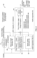
- FIG. 1 is a schematic block diagram of an illustrative system 10 for providing electrical power within an electric or hybrid electric vehicle.
- the system 10 includes a battery 11 and a battery monitoring system 12 that is configured to monitor the performance of the battery 11 and to output signals that are representative of conditions within the battery 11.
- the battery monitoring system 12 may be part of an engine management system or even a vehicle management system.
- the battery monitoring system 12 may even be part of the battery 11, for example, taking the form of a microprocessor, microcontroller, application specific integrated circuit (ASIC), or other electrical logic, sensing and memory circuitry integrated with the battery itself.
- the battery monitoring system 12 may output signals that are used to monitor battery performance, such as but not limited to battery current, internal resistance, terminal voltage and/or surface temperature. In some cases, core temperature may be used instead of surface temperature.
- the battery monitoring system 12 is operably coupled with a battery diagnostics system 14 that is configured to receive the signals that are outputted by the battery monitoring system 12.
- the battery monitoring system 12 may be operably coupled with the battery diagnostics system 14 via a vehicle network, for example.
- the battery diagnostics system 14 includes a state and health estimation block 16 that is configured to output signals representing a current health state of the battery.
- the battery diagnostics system 14 also includes a health prognostics block 18 that is configured to receive the signals outputted by the state and health estimation block 16.
- the health prognostics block 18 includes a degradation model 20 that is configured to output signals representing a loss of capacity within the battery 11 and/or changes to an internal resistance within the battery 11 and a lifetime prediction block 22 that is configured to receive the outputted signals from the degradation model 20 and to estimate an RUL (remaining useful life) value for the battery 11 and/or a CBW (cumulative battery wear cost) value for the battery 11.
- the lifetime prediction block 22 may be configured to estimate the RUL value and/or the CBW value for the battery based on the signals outputted by the degradation model.
- the lifetime prediction block 22 may be configured to estimate the RUL value and/or the CBW value for the battery 11 based also on a time of battery usage value and/or a charge throughput value for the battery 11.
- Figure 2 is a schematic block diagram of an illustrative diagnostic system 24.
- the diagnostic system 24 may be considered as being an example of the system 10 shown in Figure 1 .
- Features ascribed to the system 24 may be considered as being applicable to the system 10.
- features ascribed to the system 10 may be considered as being applicable to the system 24.
- a predicted lifetime of the battery 11 may be estimated by the health prognostics filter 26.
- the health prognostics filter 26 receives inputs from a state and health estimation block 28.
- the state and health estimation block 28 provides an estimated state of charge (SOC) for the battery 11 and an estimated core battery temperature for the battery 11.
- SOC state of charge
- the state and health estimation block 28 also provides up to date state of health information such as estimated latest capacity of the battery 11 and internal resistance within the battery 11.
- the health prognostics filter 26 includes a degradation model 30 that processes an SOH (state of health) capacity error. This error is a difference between the capacity estimated by the state and health estimation block 28 and the battery capacity estimated by the degradation model 30.
- the degradation model 30 may utilize one or more different models for modeling battery degradation. For example, one such model describes the rate of capacity change as a function of current and state of charge for different cell/battery core temperatures. Another model may parametrize the rate of capacity change as a function of temperature and state of charge where the current is first mapped into the cell temperature.
- a model update estimation block 32 provides closed-loop updating for the degradation model 30.
- the health prognostics filter 26 also includes a lifetime prediction block 34 that processes inputs such as time of battery usage, charge throughput, capacity loss and capacity loss rate in order to compute the RUL (remaining useful life) and CBW (cumulative battery wear) cost values.
- FIG. 3 is a flow diagram showing an illustrative method of diagnosing the health of a battery (such as the battery 11) within an electric or hybrid electric vehicle, the battery configured to provide power for operation of the electric or hybrid electric vehicle, the electric or hybrid electric vehicle including a battery monitoring system (such as the battery monitoring system 10).
- the method 36 includes receiving battery condition signals from the battery monitoring system, as indicated at block 38.
- the battery condition signals may include battery condition signals that are commonly available within the vehicle management system of an electric or hybrid electric vehicle, for example.
- the battery condition signals may represent one or more of a battery current of the battery, a terminal voltage of the battery, a surface temperature of the battery, and a core temperature of the battery.
- the received battery condition signals may be used to estimate an SOH (state of health) of the battery and an SOC (state of charge) of the battery, as indicated at block 40.
- the SOH of the battery may include a capacity value for the battery, and/or an internal resistance value for the battery.
- the estimated SOH and the estimated SOC may be used in combination with a degradation model to estimate one or more of a capacity loss-related parameter and a internal resistance-related parameter, as indicated at block 42.
- the estimated capacity loss-related parameter and/or the internal resistance-related parameter may be used to estimate a RUL (remaining useful life) value and/or a CBW (cumulative battery wear cost) value, as indicated at block 44.
- estimating the RUL value and/or the CBW value may further include using a time of battery usage value. Estimating the RUL value and/or the CBW value may additionally or alternatively include using a charge throughput value.
- the method 36 may further include using a closed loop feedback to update the degradation model.
- the method 36 may further include storing the estimated RUL value over time and monitoring the estimated RUL value for sudden changes, as indicated at block 48.
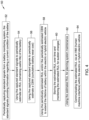
- FIG. 4 is a flow diagram showing an illustrative method 50 of optimizing battery life for a battery (such as the battery 11) within an electric or hybrid electric vehicle.
- the method 50 includes periodically capturing standard signals from a battery monitoring system, the standard signals providing information regarding a current condition of the battery, as indicated at block 52.
- the standard signals may include signals representing one or more of battery current, terminal voltage of the battery, surface temperature of the battery, and/or core temperature of the battery.
- the captured standard signals are used to periodically estimate an RUL (remaining useful life) of the battery, as indicated at block 54.
- the periodically captured standard signals may be provided to a state and health estimation block that is configured to output information describing a state of health of the battery.
- the captured standard signals are used to periodically estimate a CBW (cumulative battery wear) cost, as indicated at block 56.
- the periodically estimated RUL and/or the periodically estimated CBW are used to extend the lifetime of the battery within the hybrid vehicle, as indicated at block 58.
- Using the estimated RUL and the estimated CBW to extend the lifetime of the battery within the hybrid vehicle may include changing a control algorithm based on the estimated RUL and/or the estimated CBW.
- using the captured standard signals to periodically estimate the RUL and/or the CBW may include utilizing a degradation model of capacity loss and/or internal resistance growth. In some instances, using the captured standard signals to periodically estimate the RUL and/or the CBW may include utilizing a lifetime prediction filter block that receives as inputs one or more of time of battery usage, charge throughput, capacity loss, capacity loss rate, internal resistance growth, and internal resistance growth rate.
- the method 50 may further include storing the estimated RUL over time and monitoring the estimated RUL for sudden changes.
- the estimated RUL may be used for planning system maintenance, for example, as indicated at block 62.
- the method 50 may additionally or alternatively include communicating the estimated RUL via an HMI (human machine interface) within the electric or hybrid electric vehicle.
- the estimated RUL may be communicated to a touch screen display viewable by the driver of the electric or hybrid electric vehicle.
- Figure 5 provides a graphical representation 66 of L batt plotted versus time. This illustrates how the remaining useful life (RUL) changes until reaching 80 percent of nominal capacity.
- Equation (2) provides a definition for Q thrpt , which is the integrated current I divided by the battery-in-usage time T u :
- Q thrp Ah s ⁇ I 3600 dt Ah T u s
- Equation (4) provides the cumulative battery wear cost (CBW):
- Equation (6) provides the amount of lifetime charge, where T EOL provides useful information during charging where the degradation model has significant magnitude:
- Q lifetime is assumed to be an average value, rather than an instantaneously driven one by the T EOL (see equation (5) and equation (6)). For this reason, Q lifetime is filtered by either a running average filter, a weighted average filter or a mean average with forgetting factor.
- Figure 6 provides a flow diagram showing an illustrative method 70 for battery lifetime prognosis.
- the method 70 begins at an initialization block 72.
- a decision block 74 a determination is made as to whether the battery is being charged. If not, control passes to block 76, where Q ⁇ lifetime,k +1 is set equal to Q ⁇ lifetime,k +1 . Control then passes to block 78, where equation (1), equation (2) and equation (3) are relied upon.
- control also passes from initialization block 72 to a block 82, where equation (2) is applied. From there, control passes to block 78. From block 78, control passes to an end block 84.
- Figure 7 is a graphical representation showing how the overall cost of consuming the battery within an electric or hybrid electric vehicle may be altered by changing the control algorithm or changing parameters within the control algorithm in order to minimize. Cost is plotted versus time.
- a graph 86 represents a cumulative battery wear cost, which is an indication of how close the vehicle is to having to replace the battery, for a first control algorithm or scenario.
- a graph 88 represents the cumulative battery wear cost for a second control algorithm or scenario in which the control algorithm attempts to minimize the cumulative battery wear cost and thus maximize the expected life of the battery. It will be appreciated that the second control algorithm, represented by the graph 88, provides a lower cumulative battery wear cost, relative to that represented by the graph 86.
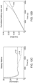
- Figure 8 provides a graphical representation of a battery degradation model in which capacity is plotted versus current.
- the battery degradation model has a pure current dependency, and dependency on SOC and temperature have been omitted.
- a point 90 represents nominal while a line 92 indicates charging the battery and a line 94 indicates discharging the battery.
- the nominal battery capacity Q 5.5 Ah
- the nominal charging current I -30A
- the nominal SOC (state of charge) is 50 percent
- the nominal degradation rate for the nominal current and nominal SOC Qr (50, -30) 3.4858x10 -9 Ah / s.
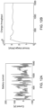
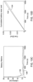
- Figure 9 is a graphical representation of a demonstration example of a nominal scenario.
- lifetime charge throughput is plotted against time.
- a line 96 shows the nominal (constant) value for the lifetime charge throughput while a line 98 shows the lifetime charge throughput in accordance with a model.
- Figure 10A shows battery current plotted against time in seconds
- Figure 10B shows charge throughput plotted against time in seconds
- Figure 10C shows battery lifetime plotted against time
- Figure 10D shows cumulative battery wear cost plotted versus time.
- a line 100 shows the nominal battery lifetime while a line 102 shows the battery lifetime in accordance with the model.
- a line 104 shows the nominal cumulative battery wear cost while a line 106 shows the cumulative battery wear cost in accordance with the model.
- the nominal case provides the RUL (here lifetime) that is based on the nominal lifetime charge throughput that is based on the nominal current reflecting typical load and nominal time of degradation.
- the model/filter processes the lifetime charge based on evolving signals having more accurate and updated inputs.
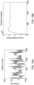
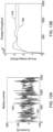
- Figure 11 is a graphical representation of a demo example of a sudden capacity change scenario.
- a sudden capacity loss of 0.55 Ah (10 percent of nominal) occurs around time equals 800 seconds.
- lifetime charge throughput is plotted against time.
- a line 108 shows the nominal (constant) value for the lifetime charge throughput while a line 110 shows the lifetime charge throughput in accordance with a model.
- Figure 12A shows battery current plotted against time
- Figure 12B shows charge throughput plotted against time
- Figure 12C shows battery lifetime plotted against time
- Figure 12D shows cumulative battery wear cost plotted versus time.
- a line 112 shows the nominal battery lifetime while a line 114 shows the battery lifetime in accordance with the model.
- the line 114 starts to diverge from the line 112 after the sudden capacity change.
- a line 116 shows the nominal cumulative battery wear cost while a line 118 shows the cumulative battery wear cost in accordance with the model.
- the line 118 starts to diverge from the line 116 after the sudden capacity change.
- Figures 13A through 13D are graphical representations of various battery parameters showing changes as a result of using different control algorithms or strategies, demonstrating the usefulness of RUL and CBW.
- Figure 13A shows battery current plotted against time
- Figure 13B shows charge throughput plotted against time
- Figure 13C shows battery lifetime plotted against time
- Figure 13D shows cumulative battery wear cost plotted versus time.
- a line 120 represents a first control strategy while a line 122 represents a second control strategy.
- a line 124 represents the first control strategy while a line 126 represents the second control strategy.
- a line 128 represents the first control strategy while a line 130 represents the second control strategy.
- a line 132 represents the first control strategy and a line 134 represents the second control strategy.
- the first control strategy generates a higher annual change and therefore wears the battery more than the second control strategy.
- the health-prediction filter based on the online processed battery current information predicts a higher RUL (or lifetime) and lower cumulative battery wear cost for the second control strategy.
- the CBW indicator can enter the EPSC (energy power split controller) cost function and thus penalize the uneconomical usage of the battery 11.
- the RUL (remaining useful life) and the CBW (cumulative battery wear cost) that have been calculated for the battery 11 by the battery diagnostics system 14 may be used by an engine management system to alter the demanded torque profiles in order to maximize the life of the battery 11.
- a demanded torque profile defines, in part, how much power (torque) is demanded from the electric motor(s) that at least partially propel the vehicle, and thus defines in part when electrical power is demanded from the battery 11, and at what rate electrical power is demanded from the battery 11.
- the engine management system may rely upon other battery condition parameters as well, such as but not limited to the current charge state of the battery 11.
- the engine management system may include an EPSC (energy power-split controller) that is configured to utilize the RUL and/or the CBW parameters to determine a demanded torque profile in order to maximize the lifetime of the battery, for example.
- power split control for a hybrid
- battery utilization for an all-electric vehicle
- MPC model predictive control
- a cost function is minimized over a time horizon; the RUL and/or CBW may be used within the cost function of an MPC, or changes or impact to RUL and/or CBW may be accounted for within the cost function to penalize such changes.
- a weighting term in an MPC or other optimization analysis may change in response to changes in RUL and/or CBW to penalize certain actions (such as penalizing actions requiring large torques) to extend battery life.
- a hybrid electric vehicle that includes both one or more electric motors as well as an internal combustion engine or fuel cell, for example, has the capability to adjust how much power is being demanded from the internal combustion engine or fuel cell at a particular time, relative to how much power is being demanded from the one or more electric motors.
- demanding relatively less power from the one or more electric motors, and temporarily relying more on the internal combustion engine or fuel cell may temporarily decrease effective fuel economy while increasing the expected life expectancy of the battery 11.
- the EPSC may be configured to utilize the RUL and/or the CBW parameters in order to minimize wear of the battery 11. It will be appreciated that the life expectancy of the battery 11 and wear of the battery 11 are inversely related, i.e., decreasing battery wear increases battery life expectancy, and vice versa.
- the EPSC may be configured to solve an optimization problem on the prediction horizon by including RUL and/or CBW parameters as terms within the optimization problem directly, or by having one or more terms, weighting values, etc. in the optimization problem derive from the RUL and/or CBW.
- the engine management system may include a vehicle cruise controller that generates a power profile for the vehicle that maximizes the lifetime of the battery 11 and/or minimizes battery wear.
- the cruise controller may allow reduction in vehicle speed while going up a hill, and may make up for such a reduction in a subsequent downhill component of a travel route.
- providing a little less power in response to the user stepping on the accelerator may help to extend the life expectancy of the battery 11, trading a small loss in total power for improving the life expectancy of the battery 11.
- the vehicle cruise controller may solve an optimization problem on the prediction horizon with the CBW indicator embedded in the cost function.
- Method examples described herein can be machine or computer-implemented at least in part. Some examples can include a computer-readable medium or machine-readable medium encoded with instructions operable to configure an electronic device to perform methods as described in the above examples.
- An implementation of such methods can include code, such as microcode, assembly language code, a higher-level language code, or the like. Such code can include computer readable instructions for performing various methods. The code may form portions of computer program products. Further, in an example, the code can be tangibly stored on one or more volatile, non-transitory, or non-volatile tangible computer-readable media, such as during execution or at other times. Examples of these tangible computer-readable media can include, but are not limited to, hard disks, removable magnetic or optical disks, magnetic cassettes, memory cards or sticks, random access memories (RAMs), read only memories (ROMs), and the like.
Landscapes
- Engineering & Computer Science (AREA)
- General Physics & Mathematics (AREA)
- Physics & Mathematics (AREA)
- Mechanical Engineering (AREA)
- Sustainable Development (AREA)
- Sustainable Energy (AREA)
- Power Engineering (AREA)
- Transportation (AREA)
- Life Sciences & Earth Sciences (AREA)
- Chemical & Material Sciences (AREA)
- Manufacturing & Machinery (AREA)
- Chemical Kinetics & Catalysis (AREA)
- Electrochemistry (AREA)
- General Chemical & Material Sciences (AREA)
- Secondary Cells (AREA)
- Electric Propulsion And Braking For Vehicles (AREA)
- Tests Of Electric Status Of Batteries (AREA)
Claims (8)
- Procédé de diagnostic de la santé d'une batterie dans un véhicule électrique électrique ou hybride, la batterie étant configurée pour fournir de la puissance pour le fonctionnement du véhicule électrique électrique ou hybride, le véhicule électrique électrique ou hybride incluant un système de surveillance de batterie, le procédé comprenant :la réception (38) de signaux d'état de batterie à partir du système de surveillance de batterie ;l'utilisation (40) des signaux d'état de batterie reçus pour l'estimation d'un SOH, état de santé, de la batterie et d'un SOC, état de charge, de la batterie ;l'utilisation (42) du SOH estimé et du SOC estimé en combinaison avec un modèle de dégradation pour l'estimation de l'un ou de plusieurs parmi un paramètre associé à la perte de capacité et un paramètre associé à la résistance interne ;l'utilisation (44) du paramètre associé à la perte de capacité et/ou du paramètre associé à la résistance interne pour l'estimation d'une valeur RUL, vie utile restante ;l'utilisation (46) d'une rétroaction en boucle fermée pour la mise à jour du modèle de dégradation ; etle stockage (48) de la valeur RUL estimée dans le temps et caractérisé parla surveillance de la valeur RUL quant à des changements soudains,dans lequel le procédé comprend en outre :
la détermination, à l'aide de la valeur RUL estimée, d'un profil de couple requis altéré à partir de moteurs électriques du véhicule électrique électrique ou hybride, le profil de couple requis altéré pour augmenter la longévité de la batterie, dans lequel l'étape de détermination du profil de couple requis altéré comprend l'utilisation d'une analyse de contrôle prédictif de modèle, MPC, visant à minimiser une fonction de coût associée à la valeur RUL sur un horizon temporel, dans lequel des termes de pondération dans l'analyse MPC sont modifiés en réponse à des changements soudains dans la valeur RUL estimée, de manière à pénaliser des actions ayant causé des changements soudains surveillés dans la valeur RUL estimée. - Procédé selon la revendication 1, dans lequel la valeur RUL estimée comprend l'utilisation d'un temps de valeur d'usage de batterie ou l'utilisation d'une valeur de débit de charge.
- Procédé selon l'une quelconque des revendications précédentes, dans lequel le SOH de la batterie comprend une valeur de capacité pour la batterie.
- Procédé selon l'une quelconque des revendications précédentes, dans lequel le SOH de la batterie comprend une valeur de résistance interne pour la batterie.
- Procédé selon l'une quelconque des revendications précédentes, dans lequel la réception de signaux d'état de batterie à partir du système de surveillance de batterie comprend la réception de signaux d'état de batterie représentant l'un ou plusieurs parmi :un courant de batterie de la batterie ;une tension de borne de la batterie ;une température de surface de la batterie ; etune température interne de la batterie.
- Système d'alimentation en puissance dans un véhicule électrique électrique ou hybride, le système comprenant :une batterie ;un système de surveillance de batterie configuré pour émettre des signaux représentant des états dans la batterie ;un système de diagnostic de batterie configuré pour recevoir les signaux émis par le système de surveillance de batterie, le système de diagnostic de batterie incluant :un bloc d'estimation d'état et de santé configuré pour émettre des signaux représentant un état de santé actuel de la batterie ; etun bloc de pronostic de santé configuré pour recevoir les signaux émis par le bloc d'estimation d'état et de santé, le bloc de pronostic de santé incluant :un modèle de dégradation configuré pour émettre des signaux représentant une perte de capacité dans la batterie et/ou une résistance interne dans la batterie ; etun bloc de prévision de longévité configuré pour recevoir les signaux émis à partir du modèle de dégradation et pour estimer une valeur RUL (vie utile restante) pour la batterie, pour utiliser une rétroaction en boucle fermée pour la mise à jour du modèle de dégradation et pour stocker la valeur RUL estimée dans le temps, et caractérisé en ce que :la valeur RUL estimée est surveillée quant à des changements soudains ; etun système de gestion de moteur configuré pour déterminer, à l'aide de la valeur RUL estimée, un profil de couple requis altéré à partir de moteurs électriques du véhicule électrique électrique ou hybride, le profil de couple requis altéré pour augmenter la longévité de la batterie, dans lequel le profil de couple requis altéré est déterminé à l'aide d'une analyse de contrôle prédictif de modèle, MPC, adaptée pour minimiser une fonction de coût associée à la valeur RUL sur un horizon temporel, dans lequel des termes de pondération dans l'analyse MPC sont configurés pour être modifiés en réponse à des changements soudains dans la valeur RUL estimée, de manière à pénaliser des actions ayant causé des changements soudains surveillés dans la valeur RUL estimée.
- Système selon la revendication 6, dans lequel le bloc de prévision de longévité est configuré pour estimer la valeur RUL pour la batterie sur la base des signaux émis par le modèle de dégradation.
- Système selon la revendication 7, dans lequel le bloc de prévision de longévité est configuré pour estimer la valeur RUL pour la batterie également sur la base d'un temps de valeur d'usage de batterie et/ou d'une valeur de débit de charge pour la batterie.
Applications Claiming Priority (1)
| Application Number | Priority Date | Filing Date | Title |
|---|---|---|---|
| US17/686,969 US20230278463A1 (en) | 2022-03-04 | 2022-03-04 | Using battery system parameters to estimate battery life expectancy within electric and hybrid electric vehicles |
Publications (3)
| Publication Number | Publication Date |
|---|---|
| EP4239351A2 EP4239351A2 (fr) | 2023-09-06 |
| EP4239351A3 EP4239351A3 (fr) | 2023-11-22 |
| EP4239351B1 true EP4239351B1 (fr) | 2025-06-04 |
Family
ID=83996117
Family Applications (1)
| Application Number | Title | Priority Date | Filing Date |
|---|---|---|---|
| EP22203429.0A Active EP4239351B1 (fr) | 2022-03-04 | 2022-10-24 | Utilisation de paramètres de système de batterie pour estimer l'espérance de vie de batterie dans des véhicules électriques et hybrides électriques |
Country Status (3)
| Country | Link |
|---|---|
| US (1) | US20230278463A1 (fr) |
| EP (1) | EP4239351B1 (fr) |
| CN (1) | CN116125324A (fr) |
Families Citing this family (6)
| Publication number | Priority date | Publication date | Assignee | Title |
|---|---|---|---|---|
| KR20250041431A (ko) * | 2023-09-18 | 2025-03-25 | 현대자동차주식회사 | 차량 배터리 제어 장치 및 그 방법 |
| EP4571335B1 (fr) * | 2023-12-13 | 2026-05-06 | Skeleton Technologies GmbH | Procédé de détermination d'une durée de vie restante d'une unité de stockage d'énergie, dispositif de gestion de stockage d'énergie et système |
| KR102849370B1 (ko) * | 2023-12-20 | 2025-08-26 | 주식회사 엘지에너지솔루션 | 배터리 관리 장치, 배터리 관리 방법 및 차량 |
| WO2025135474A1 (fr) * | 2023-12-20 | 2025-06-26 | 주식회사 엘지에너지솔루션 | Dispositif de gestion de batterie, procédé de gestion de batterie et véhicule |
| CN118465594B (zh) * | 2024-05-22 | 2024-10-29 | 杭州华塑科技股份有限公司 | 一种电池soh的确定方法、装置、设备及存储介质 |
| CN120029142B (zh) * | 2025-02-06 | 2025-10-24 | 无锡科铭新汽车电子系统有限公司 | 一种基于车联网的汽车设备远程控制系统及方法 |
Family Cites Families (11)
| Publication number | Priority date | Publication date | Assignee | Title |
|---|---|---|---|---|
| JP4179330B2 (ja) * | 2006-03-31 | 2008-11-12 | トヨタ自動車株式会社 | ハイブリッド車両用電池情報表示装置 |
| FR2938658B1 (fr) * | 2008-11-17 | 2010-11-05 | Peugeot Citroen Automobiles Sa | Procede pour determiner l'etat de sante d'une source electrochimique pour la traction electrique de vehicules |
| FR3016218B1 (fr) * | 2014-01-03 | 2016-01-01 | Commissariat Energie Atomique | Procede, dispositif et systeme d'estimation de l'etat de sante d'une batterie d'un vehicule electrique ou hybride en condition d'utilisation, et procede de construction d'un modele pour une telle estimation |
| US20150349385A1 (en) * | 2014-04-01 | 2015-12-03 | Medtronic, Inc. | Method and System for Predicting Useful Life of a Rechargeable Battery |
| US10401433B2 (en) * | 2015-01-21 | 2019-09-03 | Samsung Electronics Co., Ltd. | Method and apparatus for estimating battery life |
| KR102424528B1 (ko) * | 2015-06-11 | 2022-07-25 | 삼성전자주식회사 | 배터리의 상태를 추정하는 장치 및 방법 |
| US10209314B2 (en) * | 2016-11-21 | 2019-02-19 | Battelle Energy Alliance, Llc | Systems and methods for estimation and prediction of battery health and performance |
| CN108638890B (zh) * | 2018-05-16 | 2020-03-31 | 蔚来汽车有限公司 | 服务器、保养终端、动力电池保养方法、装置及系统 |
| EP4004570B1 (fr) * | 2019-07-24 | 2024-08-07 | Eco Stor AS | Procédé et dispositif de prédiction d'état de santé et de durée de vie restante de batteries de véhicule électrique usagées |
| CN112757964A (zh) * | 2019-10-17 | 2021-05-07 | 郑州宇通客车股份有限公司 | 混合动力车辆参数配置方法及计算机可读介质 |
| EP4621514A3 (fr) * | 2020-06-08 | 2025-12-17 | Hitachi Energy Ltd | Procédé et système informatique pour effectuer une analyse pronostique de létat d'un actif |
-
2022
- 2022-03-04 US US17/686,969 patent/US20230278463A1/en not_active Abandoned
- 2022-10-24 EP EP22203429.0A patent/EP4239351B1/fr active Active
-
2023
- 2023-03-03 CN CN202310201607.5A patent/CN116125324A/zh active Pending
Also Published As
| Publication number | Publication date |
|---|---|
| CN116125324A (zh) | 2023-05-16 |
| EP4239351A2 (fr) | 2023-09-06 |
| EP4239351A3 (fr) | 2023-11-22 |
| US20230278463A1 (en) | 2023-09-07 |
Similar Documents
| Publication | Publication Date | Title |
|---|---|---|
| EP4239351A2 (fr) | Utilisation de paramètres de système de batterie pour estimer l'espérance de vie de batterie dans des véhicules électriques et hybrides électriques | |
| EP3916884B1 (fr) | Procédé de diagnostic de durée de vie restante de module de batterie secondaire et système de diagnostic de durée de vie restante | |
| EP3245096B1 (fr) | Procédé et agencement permettant de déterminer une valeur de l'état énergétique d'une batterie dans un véhicule | |
| US9130248B2 (en) | Modeling changes in the state-of-charge open circuit voltage curve by using regressed parameters in a reduced order physics based model | |
| JP4073228B2 (ja) | 充電状態予測方法及びバッテリーのための装置 | |
| US10663526B2 (en) | Battery management terminal and battery management system | |
| EP3346542A1 (fr) | Dispositif de gestion de batterie, système de batterie et système de commande de véhicule hybride | |
| US9197078B2 (en) | Battery parameter estimation | |
| US20160006275A1 (en) | System and method for battery open circuit voltage estimation | |
| EP3924215B1 (fr) | Procédé de gestion d'un système de stockage d'énergie d'un véhicule | |
| CN113015918A (zh) | 用于确定二次电池的健康状态的方法和电池管理系统 | |
| CN104723895A (zh) | 车辆和用于估计电池的衰减的方法 | |
| CN112319462B (zh) | 一种插电式混合动力汽车能量管理方法 | |
| El Ouazzani et al. | MSCC-DRL: Multi-Stage constant current based on deep reinforcement learning for fast charging of lithium ion battery | |
| CN114789675A (zh) | 确定要采取的动作的设备和方法以及至少部分电动车辆 | |
| US12109909B2 (en) | Goal-based electric vehicle charging | |
| CN113167837A (zh) | 车辆续驶里程估计器 | |
| JP6977697B2 (ja) | 電池制御装置 | |
| EP4059770B1 (fr) | Procédé et système pour estimer la consommation d'énergie actuelle d'un véhicule à propulsion électrique | |
| CN119189971A (zh) | 一种基于等效因子的增程式矿卡动态能耗管理方法 | |
| US20250332957A1 (en) | Method and computer system for controlling a charging cycle of an energy storage system of an electric vehicle, computer program product, a non-transitory computer-readable medium, a control system and an electric vehicle | |
| US20250306111A1 (en) | Estimation of auxiliary loads in hybrid or battery electric vehicles for failure detection | |
| CN114834431B (zh) | 考虑动力电池衰退抑制的电动汽车能量管理方法及系统 | |
| CN119378823B (zh) | 增程式混动轻卡能量管理控制方法、装置及电子设备 | |
| Eider et al. | Dynamic generation of recommendations for ev battery health |
Legal Events
| Date | Code | Title | Description |
|---|---|---|---|
| PUAI | Public reference made under article 153(3) epc to a published international application that has entered the european phase |
Free format text: ORIGINAL CODE: 0009012 |
|
| STAA | Information on the status of an ep patent application or granted ep patent |
Free format text: STATUS: REQUEST FOR EXAMINATION WAS MADE |
|
| 17P | Request for examination filed |
Effective date: 20221024 |
|
| AK | Designated contracting states |
Kind code of ref document: A2 Designated state(s): AL AT BE BG CH CY CZ DE DK EE ES FI FR GB GR HR HU IE IS IT LI LT LU LV MC ME MK MT NL NO PL PT RO RS SE SI SK SM TR |
|
| PUAL | Search report despatched |
Free format text: ORIGINAL CODE: 0009013 |
|
| AK | Designated contracting states |
Kind code of ref document: A3 Designated state(s): AL AT BE BG CH CY CZ DE DK EE ES FI FR GB GR HR HU IE IS IT LI LT LU LV MC ME MK MT NL NO PL PT RO RS SE SI SK SM TR |
|
| RIC1 | Information provided on ipc code assigned before grant |
Ipc: G01R 31/367 20190101ALI20231016BHEP Ipc: B60L 58/16 20190101ALI20231016BHEP Ipc: G01R 31/392 20190101AFI20231016BHEP |
|
| P01 | Opt-out of the competence of the unified patent court (upc) registered |
Effective date: 20231110 |
|
| GRAP | Despatch of communication of intention to grant a patent |
Free format text: ORIGINAL CODE: EPIDOSNIGR1 |
|
| STAA | Information on the status of an ep patent application or granted ep patent |
Free format text: STATUS: GRANT OF PATENT IS INTENDED |
|
| RIC1 | Information provided on ipc code assigned before grant |
Ipc: B60L 3/12 20060101ALI20250317BHEP Ipc: B60L 58/12 20190101ALI20250317BHEP Ipc: G01R 31/367 20190101ALI20250317BHEP Ipc: B60L 58/16 20190101ALI20250317BHEP Ipc: G01R 31/392 20190101AFI20250317BHEP |
|
| GRAS | Grant fee paid |
Free format text: ORIGINAL CODE: EPIDOSNIGR3 |
|
| INTG | Intention to grant announced |
Effective date: 20250326 |
|
| GRAA | (expected) grant |
Free format text: ORIGINAL CODE: 0009210 |
|
| STAA | Information on the status of an ep patent application or granted ep patent |
Free format text: STATUS: THE PATENT HAS BEEN GRANTED |
|
| AK | Designated contracting states |
Kind code of ref document: B1 Designated state(s): AL AT BE BG CH CY CZ DE DK EE ES FI FR GB GR HR HU IE IS IT LI LT LU LV MC ME MK MT NL NO PL PT RO RS SE SI SK SM TR |
|
| REG | Reference to a national code |
Ref country code: GB Ref legal event code: FG4D |
|
| REG | Reference to a national code |
Ref country code: CH Ref legal event code: EP |
|
| REG | Reference to a national code |
Ref country code: DE Ref legal event code: R096 Ref document number: 602022015428 Country of ref document: DE |
|
| REG | Reference to a national code |
Ref country code: IE Ref legal event code: FG4D |
|
| REG | Reference to a national code |
Ref country code: NL Ref legal event code: MP Effective date: 20250604 |
|
| PG25 | Lapsed in a contracting state [announced via postgrant information from national office to epo] |
Ref country code: FI Free format text: LAPSE BECAUSE OF FAILURE TO SUBMIT A TRANSLATION OF THE DESCRIPTION OR TO PAY THE FEE WITHIN THE PRESCRIBED TIME-LIMIT Effective date: 20250604 Ref country code: ES Free format text: LAPSE BECAUSE OF FAILURE TO SUBMIT A TRANSLATION OF THE DESCRIPTION OR TO PAY THE FEE WITHIN THE PRESCRIBED TIME-LIMIT Effective date: 20250604 |
|
| REG | Reference to a national code |
Ref country code: LT Ref legal event code: MG9D |
|
| PG25 | Lapsed in a contracting state [announced via postgrant information from national office to epo] |
Ref country code: NO Free format text: LAPSE BECAUSE OF FAILURE TO SUBMIT A TRANSLATION OF THE DESCRIPTION OR TO PAY THE FEE WITHIN THE PRESCRIBED TIME-LIMIT Effective date: 20250904 Ref country code: GR Free format text: LAPSE BECAUSE OF FAILURE TO SUBMIT A TRANSLATION OF THE DESCRIPTION OR TO PAY THE FEE WITHIN THE PRESCRIBED TIME-LIMIT Effective date: 20250905 |
|
| PG25 | Lapsed in a contracting state [announced via postgrant information from national office to epo] |
Ref country code: PL Free format text: LAPSE BECAUSE OF FAILURE TO SUBMIT A TRANSLATION OF THE DESCRIPTION OR TO PAY THE FEE WITHIN THE PRESCRIBED TIME-LIMIT Effective date: 20250604 |
|
| PG25 | Lapsed in a contracting state [announced via postgrant information from national office to epo] |
Ref country code: BG Free format text: LAPSE BECAUSE OF FAILURE TO SUBMIT A TRANSLATION OF THE DESCRIPTION OR TO PAY THE FEE WITHIN THE PRESCRIBED TIME-LIMIT Effective date: 20250604 |
|
| PG25 | Lapsed in a contracting state [announced via postgrant information from national office to epo] |
Ref country code: HR Free format text: LAPSE BECAUSE OF FAILURE TO SUBMIT A TRANSLATION OF THE DESCRIPTION OR TO PAY THE FEE WITHIN THE PRESCRIBED TIME-LIMIT Effective date: 20250604 |
|
| PG25 | Lapsed in a contracting state [announced via postgrant information from national office to epo] |
Ref country code: RS Free format text: LAPSE BECAUSE OF FAILURE TO SUBMIT A TRANSLATION OF THE DESCRIPTION OR TO PAY THE FEE WITHIN THE PRESCRIBED TIME-LIMIT Effective date: 20250904 |
|
| PG25 | Lapsed in a contracting state [announced via postgrant information from national office to epo] |
Ref country code: LV Free format text: LAPSE BECAUSE OF FAILURE TO SUBMIT A TRANSLATION OF THE DESCRIPTION OR TO PAY THE FEE WITHIN THE PRESCRIBED TIME-LIMIT Effective date: 20250604 |
|
| PG25 | Lapsed in a contracting state [announced via postgrant information from national office to epo] |
Ref country code: NL Free format text: LAPSE BECAUSE OF FAILURE TO SUBMIT A TRANSLATION OF THE DESCRIPTION OR TO PAY THE FEE WITHIN THE PRESCRIBED TIME-LIMIT Effective date: 20250604 |
|
| PG25 | Lapsed in a contracting state [announced via postgrant information from national office to epo] |
Ref country code: PT Free format text: LAPSE BECAUSE OF FAILURE TO SUBMIT A TRANSLATION OF THE DESCRIPTION OR TO PAY THE FEE WITHIN THE PRESCRIBED TIME-LIMIT Effective date: 20251006 |
|
| REG | Reference to a national code |
Ref country code: AT Ref legal event code: MK05 Ref document number: 1800813 Country of ref document: AT Kind code of ref document: T Effective date: 20250604 |
|
| PG25 | Lapsed in a contracting state [announced via postgrant information from national office to epo] |
Ref country code: IS Free format text: LAPSE BECAUSE OF FAILURE TO SUBMIT A TRANSLATION OF THE DESCRIPTION OR TO PAY THE FEE WITHIN THE PRESCRIBED TIME-LIMIT Effective date: 20251004 |
|
| PGFP | Annual fee paid to national office [announced via postgrant information from national office to epo] |
Ref country code: DE Payment date: 20251028 Year of fee payment: 4 |
|
| PG25 | Lapsed in a contracting state [announced via postgrant information from national office to epo] |
Ref country code: SM Free format text: LAPSE BECAUSE OF FAILURE TO SUBMIT A TRANSLATION OF THE DESCRIPTION OR TO PAY THE FEE WITHIN THE PRESCRIBED TIME-LIMIT Effective date: 20250604 Ref country code: AT Free format text: LAPSE BECAUSE OF FAILURE TO SUBMIT A TRANSLATION OF THE DESCRIPTION OR TO PAY THE FEE WITHIN THE PRESCRIBED TIME-LIMIT Effective date: 20250604 |
|
| PGFP | Annual fee paid to national office [announced via postgrant information from national office to epo] |
Ref country code: FR Payment date: 20251027 Year of fee payment: 4 |
|
| PG25 | Lapsed in a contracting state [announced via postgrant information from national office to epo] |
Ref country code: CZ Free format text: LAPSE BECAUSE OF FAILURE TO SUBMIT A TRANSLATION OF THE DESCRIPTION OR TO PAY THE FEE WITHIN THE PRESCRIBED TIME-LIMIT Effective date: 20250604 |
|
| PG25 | Lapsed in a contracting state [announced via postgrant information from national office to epo] |
Ref country code: EE Free format text: LAPSE BECAUSE OF FAILURE TO SUBMIT A TRANSLATION OF THE DESCRIPTION OR TO PAY THE FEE WITHIN THE PRESCRIBED TIME-LIMIT Effective date: 20250604 |
|
| PG25 | Lapsed in a contracting state [announced via postgrant information from national office to epo] |
Ref country code: SK Free format text: LAPSE BECAUSE OF FAILURE TO SUBMIT A TRANSLATION OF THE DESCRIPTION OR TO PAY THE FEE WITHIN THE PRESCRIBED TIME-LIMIT Effective date: 20250604 |
|
| PG25 | Lapsed in a contracting state [announced via postgrant information from national office to epo] |
Ref country code: IT Free format text: LAPSE BECAUSE OF FAILURE TO SUBMIT A TRANSLATION OF THE DESCRIPTION OR TO PAY THE FEE WITHIN THE PRESCRIBED TIME-LIMIT Effective date: 20250604 |
|
| REG | Reference to a national code |
Ref country code: DE Ref legal event code: R097 Ref document number: 602022015428 Country of ref document: DE |
|
| PG25 | Lapsed in a contracting state [announced via postgrant information from national office to epo] |
Ref country code: RO Free format text: LAPSE BECAUSE OF FAILURE TO SUBMIT A TRANSLATION OF THE DESCRIPTION OR TO PAY THE FEE WITHIN THE PRESCRIBED TIME-LIMIT Effective date: 20250604 |
|
| PLBE | No opposition filed within time limit |
Free format text: ORIGINAL CODE: 0009261 |
|
| STAA | Information on the status of an ep patent application or granted ep patent |
Free format text: STATUS: NO OPPOSITION FILED WITHIN TIME LIMIT |
|
| PG25 | Lapsed in a contracting state [announced via postgrant information from national office to epo] |
Ref country code: DK Free format text: LAPSE BECAUSE OF FAILURE TO SUBMIT A TRANSLATION OF THE DESCRIPTION OR TO PAY THE FEE WITHIN THE PRESCRIBED TIME-LIMIT Effective date: 20250604 |
|
| REG | Reference to a national code |
Ref country code: CH Ref legal event code: L10 Free format text: ST27 STATUS EVENT CODE: U-0-0-L10-L00 (AS PROVIDED BY THE NATIONAL OFFICE) Effective date: 20260416 |
|
| 26N | No opposition filed |
Effective date: 20260305 |