EP4239610A1 - Katastrophenverhinderungsvorrichtung - Google Patents
Katastrophenverhinderungsvorrichtung Download PDFInfo
- Publication number
- EP4239610A1 EP4239610A1 EP20959864.8A EP20959864A EP4239610A1 EP 4239610 A1 EP4239610 A1 EP 4239610A1 EP 20959864 A EP20959864 A EP 20959864A EP 4239610 A1 EP4239610 A1 EP 4239610A1
- Authority
- EP
- European Patent Office
- Prior art keywords
- test
- detector
- outer cover
- light
- disaster prevention
- Prior art date
- Legal status (The legal status is an assumption and is not a legal conclusion. Google has not performed a legal analysis and makes no representation as to the accuracy of the status listed.)
- Granted
Links
Images


Classifications
-
- G—PHYSICS
- G08—SIGNALLING
- G08B—SIGNALLING SYSTEMS, e.g. PERSONAL CALLING SYSTEMS; ORDER TELEGRAPHS; ALARM SYSTEMS
- G08B17/00—Fire alarms; Alarms responsive to explosion
- G08B17/06—Electric actuation of the alarm, e.g. using a thermally-operated switch
-
- G—PHYSICS
- G08—SIGNALLING
- G08B—SIGNALLING SYSTEMS, e.g. PERSONAL CALLING SYSTEMS; ORDER TELEGRAPHS; ALARM SYSTEMS
- G08B17/00—Fire alarms; Alarms responsive to explosion
- G08B17/10—Actuation by presence of smoke or gases, e.g. automatic alarm devices for analysing flowing fluid materials by the use of optical means
- G08B17/103—Actuation by presence of smoke or gases, e.g. automatic alarm devices for analysing flowing fluid materials by the use of optical means using a light emitting and receiving device
-
- G—PHYSICS
- G08—SIGNALLING
- G08B—SIGNALLING SYSTEMS, e.g. PERSONAL CALLING SYSTEMS; ORDER TELEGRAPHS; ALARM SYSTEMS
- G08B17/00—Fire alarms; Alarms responsive to explosion
- G08B17/10—Actuation by presence of smoke or gases, e.g. automatic alarm devices for analysing flowing fluid materials by the use of optical means
- G08B17/11—Actuation by presence of smoke or gases, e.g. automatic alarm devices for analysing flowing fluid materials by the use of optical means using an ionisation chamber for detecting smoke or gas
- G08B17/113—Constructional details
-
- G—PHYSICS
- G08—SIGNALLING
- G08B—SIGNALLING SYSTEMS, e.g. PERSONAL CALLING SYSTEMS; ORDER TELEGRAPHS; ALARM SYSTEMS
- G08B17/00—Fire alarms; Alarms responsive to explosion
- G08B17/10—Actuation by presence of smoke or gases, e.g. automatic alarm devices for analysing flowing fluid materials by the use of optical means
-
- G—PHYSICS
- G08—SIGNALLING
- G08B—SIGNALLING SYSTEMS, e.g. PERSONAL CALLING SYSTEMS; ORDER TELEGRAPHS; ALARM SYSTEMS
- G08B29/00—Checking or monitoring of signalling or alarm systems; Prevention or correction of operating errors, e.g. preventing unauthorised operation
- G08B29/12—Checking intermittently signalling or alarm systems
- G08B29/14—Checking intermittently signalling or alarm systems checking the detection circuits
- G08B29/145—Checking intermittently signalling or alarm systems checking the detection circuits of fire detection circuits
-
- G—PHYSICS
- G08—SIGNALLING
- G08B—SIGNALLING SYSTEMS, e.g. PERSONAL CALLING SYSTEMS; ORDER TELEGRAPHS; ALARM SYSTEMS
- G08B5/00—Visible signalling systems, e.g. visible personal calling systems or remote indication of seats occupied
- G08B5/22—Visible signalling systems, e.g. visible personal calling systems or remote indication of seats occupied using electric transmission; using electromagnetic transmission
- G08B5/36—Visible signalling systems, e.g. visible personal calling systems or remote indication of seats occupied using electric transmission; using electromagnetic transmission using visible light sources
Definitions
- the present invention relates to a disaster prevention apparatus.
- a detector that is installed on a ceiling, etc. to detect heat caused by fire has been known (for example, refer to Patent Literature 1).
- a test is periodically performed on the detector, but the detector is configured to output information about the test by causing an indicator light to emit light, the indicator light being provided on an outer cover of the detector.
- Patent Literature 1 Laid-Open Patent Publication in Japan No. 2012-198757
- the invention is conceived in view of the foregoing problem, and an object of the invention is to provide a disaster prevention apparatus that allows information about a test to be identified even in a state where at least a part of the disaster prevention apparatus is covered with a test apparatus.
- a disaster prevention apparatus of claim 1 is a disaster prevention apparatus comprises: an outer cover; and an indicator that outputs at least information about a test of the disaster prevention apparatus by emitting light, and that is provided in the outer cover, wherein when at least a part of the outer cover is covered with a test apparatus in order to perform the test of the disaster prevention apparatus, at least a part of an indication surface of the indicator is exposed to an outside of the test apparatus.
- the disaster prevention apparatus of claim 2 according to the disaster prevention apparatus of claim 1, wherein the indicator protrudes from a side portion of the outer cover.
- the disaster prevention apparatus of claim 3 according to the disaster prevention apparatus of claim 1 or 2, wherein the indicator is formed in at least a side portion of the outer cover.
- the disaster prevention apparatus of claim 4 according to the disaster prevention apparatus of any one of claims 1 to 3, wherein the indicator is formed in at least an edge portion of a front portion of the outer cover.
- the disaster prevention apparatus of claim 5 according to the disaster prevention apparatus of any one of claims 1 to 4, wherein the indicator is a light guide that is formed in the outer cover, and that guides light from a light emitter.
- the disaster prevention apparatus of claim 6 according to the disaster prevention apparatus of any one of claims 1 to 5, wherein the indicator is a thin portion that is thinner than other portions of the outer cover, and that is irradiated with light from a light emitter.
- the disaster prevention apparatus of claim 7 according to the disaster prevention apparatus of any one of claims 1 to 6, wherein the disaster prevention apparatus is at least a heat detector.
- the disaster prevention apparatus of claim 1 when at least a part of the outer cover is covered with the test apparatus in order to perform a test of the disaster prevention apparatus, at least a part of the indication surface of the indicators is exposed to the outside of the test apparatus, so that, for example, even in a state where at least a part of the disaster prevention apparatus is covered with the test apparatus, a part of the indicators is visible, so that information about the test can be identified.
- the indicators protrude from a side portion of an outer cover, for example, the indicators are reliably visible, so that information about the test can be reliably identified.
- the indicator is formed at the side portion of the outer cover, for example, the indicator is visible in any direction with respect to the disaster prevention apparatus, so that information about the test can be reliably identified.
- the indicator is formed at the edge portion of the front portion of the outer cover, for example, the indicator is visible even from directly below the disaster prevention apparatus, so that information on the test can be reliably identified.
- the indicator is a part of the light guide, for example, the degree of freedom in the installation position of a light source for the indicator (for example, the light emitter) can be improved, so that the degree of freedom in designing the disaster prevention apparatus can be improved.
- the indicator is a part of the thin portions, for example, providing another component for emitting light is not required, so that the number of components can be reduced, and the cost can be reduced.
- the disaster prevention apparatus is at least a heat detector, for example, it is possible to provide a heat detector that allows information about the test to be ascertained even when at least part of the disaster prevention apparatus is covered by the test apparatus.
- the embodiments generally relate to the disaster prevention apparatus.
- the "disaster prevention apparatus” is an apparatus used for prevention of a disaster, for example, is a concept including an apparatus that detects an abnormality of a monitoring region, etc., and as one example, is a concept including a heat detector, a fire detector, a gas detector, a smoke detector, etc.
- the "disaster prevention apparatus” includes, for example, an outer cover and an indicator.
- the "monitoring region” is a region to be monitored by the disaster prevention apparatus, specifically, is a certain extent of space and, for example, is a concept including a room (for example, a first-floor room A, a first-floor room B, etc.), a corridor, and a stair of a building, etc.
- the "abnormality of the monitoring region” indicates that the state of the monitoring region is different from a normal state and, specifically, is a concept including a fire outbreak, a gas leakage, etc.
- the “outer cover” covers, for example, at least some of components of the disaster prevention apparatus.
- the "indicator” is an indicator that outputs at least information about a test of the disaster prevention apparatus by emitting light, that is provided in the outer cover, and specifically, is a concept including an indicator, a portion, etc. configured such that at least a part of an indication surface of the indicator is exposed to the outside of a test apparatus when at least a part of the outer cover is covered with the test apparatus in order to perform a test of the disaster prevention apparatus.
- the "indicator” is, for example, a concept including an indicator, a portion, etc. protruding from a side portion of the cover, is a concept including an indicator, a portion, etc. formed in at least an edge portion of a front portion of the outer cover, is a concept including a light guide, etc., and is a concept including a thin portion, etc.
- the "indication surface of the indicator” is, for example, a concept including a surface of the indicator that is exposed to the outside of the disaster prevention apparatus, that emits light, and that is viewed by a user, etc.
- the "light guide” is, for example, a concept including a light guide, a portion, etc. that is formed in the outer cover and that guides light from a light emitter.
- the "thin portion” is, for example, a concept including a portion that is thinner than other portions of the outer cover and that is irradiated with light from the light emitter, etc., and is a concept including a portion that transmits some of irradiation light, etc.
- the "light emitter” is, for example, a unit that outputs light.
- the "disaster prevention apparatus" is a heat detector
- the case where the indicator is the light guide will be described
- the case where the indicator is the thin portion will be described.
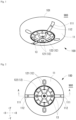
- FIG. 1 is a perspective view of the detector according to the embodiment of the invention
- FIG. 2 is a plan view of the detector
- FIG. 3 is a side view of the detector
- FIG. 4 is a cross-sectional view taken along line A-A of FIG. 2 .
- a Z axis, and an X axis and a Y axis orthogonal to the Z axis will be described as indicating a vertical direction and a horizontal direction, respectively.
- a "front portion", a "back portion”, and a “side portion” will be described as terms referring to parts of a detector 100.
- the detector 100 when the detector 100 is installed on an attachment object 900 that is a ceiling surface, a portion of the detector 100 located on a floor surface side (side opposite the attachment object 900 with respect the detector 100) (-Z direction in FIG. 3 ) is referred to as the "front portion", and a portion of the detector 100 facing the attachment object 900 that is a ceiling surface (+Z direction in FIG. 3 ) is referred to as the "back portion”.
- a peripheral surface of the detector 100 connected to the "front portion” and to the "back portion” is the "side portion”.
- the definitions of the "front portion", the "back portion", and the "side portion” also are the same in a second embodiment.
- the detector 1 of each drawing of FIGS. 1 to 4 is a disaster prevention apparatus, specifically, is a heat detector that detects heat, is attached to, for example, the attachment object 900 that is a ceiling surface, through an attachment portion 101 of the detector 100 of FIG. 3 (for example, a so-called "detector base" and a detailed structure is not shown), and as one example, includes an outer cover 11, a protective portion 12, and prevention portions 13 of FIG. 1 , and a thermistor 14 and a light emitter 15 of FIG. 4 .
- the outer cover 11 of FIG. 1 covers at least some of components of the detector 100.
- a specific type or configuration of the outer cover 11 is any type or any configuration, however, for example, as shown in FIG. 3 , the outer cover 11 includes a cylindrical portion of which the diameter is the same even when extending away from the attachment portion 101, and a tapered portion that is reduced in diameter as extending away from the attachment portion 101, has a light-shielding property except for a specified portion, and includes light guide portions 111 and operation holes 112 of FIG. 2 .
- the "light-shielding property" is the ability to block light and, for example, is a concept indicating the ability of the outer cover 11 to prevent light from passing from the inside to the outside.
- the light guide portions 111 are the aforementioned indicators, and the light guides.
- a specific type or configuration of the light guide portions 111 is any type or any configuration, however, for example, the light guide portions 111 is formed in a part of the outer cover 11, are made of any material so as to function as light guides that guide and emit light, are formed separately from portions of the outer cover 11 having a light-shielding property, and allow light to pass through the outer cover 11 from the inside to the outside.
- indication surfaces surfaces exposed to the outside of the detector 100 shown in FIGS.
- the light guide portions 111 extend from a front portion side (-Z direction) of the outer cover 11 to a side portion side (+X direction or -X direction) of the outer cover 11, two light guide portions 111 are provided, as shown in FIG. 2 , the indication surfaces of the light guide portions 111 have a linear shape when viewed from the front portion side of the outer cover 11, and the light guide portions 111 are provided at positions to correspond to the positions of the operation holes 112.
- the operation holes 112 are operation portions for physically operating the detector 100.
- a specific type or configuration of the operation holes 112 is any type or any configuration, however, for example, the operation holes 112 are, for example, holes into which a projection of a predetermined jig is inserted to rotate the outer cover 11 of the detector 100 with respect to the attachment portion 101.
- the protective portion 12 of FIG. 1 is a detection element protector.
- the "detection element protector” accommodates and protects, for example, the thermistor 14 that is a detection element.
- a specific type or configuration of the protective portion 12 is any type or any configuration, however, for example, the protective portion 12 is formed in a part of the outer cover 11, is made of any material so as to function as a light guide that guides and emits light, is formed separately from the portions of the outer cover 11 having a light-shielding property, and allows light to pass through the outer cover 11 from the inside to the outside.
- the protective portion 12 protects, for example, the thermistor 14 of FIG.
- the protective portion 12 includes, for example, a frame portion 121 and opening portions 122 of FIG. 1 , and a spectroscopic portion 123 of FIG. 4 .
- the frame portion 121 is, for example, a portion forming an outer shape of at least a part of the protective portion 12, and is a portion including one circular member forming a tip portion (-Z direction) of the detector 100, and six support members between the circular member and the outer cover 11, the support members supporting the circular member.
- the opening portions 122 are, for example, portions through which a hot air current flows in and out with respect to the thermistor 14 provided in the hollow portion of the protective portion 12, and six opening portions 122 are provided in such a manner to be partitioned off by the aforementioned six support members of the frame portion 121.
- the spectroscopic portion 123 is, for example, a portion that refracts, disperses, or reflects light output from the light emitter 15, and is a portion facing the light emitter 15.
- the prevention portions 13 of FIG. 1 are preventors that prevent a contact object from coming into contact with the thermistor 14 accommodated in the protective portion 12.
- the "contact object” is an object that is prevented from coming into contact by the prevention portions 13, and is a concept including, for example, a user's finger, etc.
- a specific type or configuration of the prevention portions 13 is any type or any configuration, however, the prevention portions 13 are, for example, projections provided in the opening portions 122.
- the thermistor 14 of FIG. 4 is a detection element.
- the "detection element” is, for example, a component that detects a physical quantity of a detection target.
- the "physical quantity of the detection target” is, for example, a quantity that can be generated or changed due to an abnormality of the monitoring region, and as one example, is a concept including temperature caused by heat or a hot air current, etc.
- a specific type or configuration of the thermistor 14 is any type or any configuration, however, the thermistor 14 detects, for example, a temperature caused by heat or a hot air current, protrudes in a direction orthogonal to the direction in which the outer cover 11 is widened (Z-axis direction), and is accommodated in the protective portion 12.
- the light emitter 15 of FIG. 4 is the aforementioned light emitter.
- a specific type or configuration of the light emitter 15 is any type or any configuration, however, for example, the light emitter 15 causes the light guide portions 111 and the protective portion 12 to emit light, outputs light toward the spectroscopic portion 123, and can be formed of a light emitting diode, etc.
- the detector 100 emits light at any timing, and for example, any timing such as when information about a test of the detector 100 is output or when the detector 100 determines a fire outbreak based on a temperature of heat detected by the thermistor 14 is assumed.
- FIG. 5 is a view showing an optical path in FIG. 4 as an example.
- a control unit (not shown) of the detector 100 of FIG. 5 causes the light emitter 15 to output light.
- the light from the light emitter 15 is refracted, dispersed, or reflected by the spectroscopic portion 123, and as shown in FIG. 5 , is guided to the entireties of the light guide portions 111 and the protective portion 12.
- FIG. 5 for convenience of description, only an optical path of light from the light emitter 15 on the left side of the drawing sheet is shown, but in reality, light is also output from the light emitter 15 on the right side of the drawing sheet, and is guided to the entireties of the light guide portions 111 and the protective portion 12. Then, the entireties of the light guide portions 111 and the protective portion 12 of FIG. 1 emit the light.
- test indicates testing the capability of the detector 100.
- specific contents of the test of the detector 100 are any contents, however, for example, the case will be described where a test is performed to determine whether heat applied by the detector 100 is detected, when the heat is applied to the detector 100 by simulating a fire outbreak using a test apparatus to be described later.
- a control unit of the detector 100 will be described below as being configured to acquire a result of detection of a temperature by the thermistor 14, to detect a fire when the acquired temperature is a threshold value or higher, and to output information indicating that the detector 100 has detected the fire in a test by continuing to output red light from the light emitter 15 of FIG. 4 .
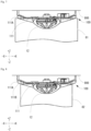
- FIG. 6 is a side view showing a test apparatus and the detector
- FIG. 7 is a view of a test jig with respect to the cross-sectional view of FIG. 4
- FIG. 8 is a view of a test adapter with respect to the cross-sectional view of FIG. 4
- a test jig 81 and a test adapter 82 are shown by an alternate long and short-dashed line.
- a part of the detector 100 is provided in a hollow portion inside the test jig 81 and the test adapter 82, and is not actually visible, however, for convenience of description, is shown by a solid line.
- a test of the detector 100 is performed using a test apparatus 800 of FIG. 6 .
- the test apparatus 800 is an apparatus used to perform a test of the detector 100, and includes, for example, a handle portion and the test jig 81 as shown in FIG. 6 , and optionally includes the test adapter 82 of FIG. 8 .
- the test jig 81 is the aforementioned test apparatus, specifically, is provided at a tip of the rod-shaped handle portion of the test apparatus 800, for example, has a cylindrical shape including a hollow portion for accommodating at least a part (for example, the protective portion 12, etc.) of the detector 100 inside and for applying heat, and is made of metal.
- the size of the test jig 81 is any size, however, for example, as shown in FIG. 7 , the case will be described in which an outer diameter of the test jig 81 is larger than an outer diameter of the detector 100 and an inner diameter of the test jig 81 is smaller than the outer diameter of the detector 100.
- the test adapter 82 of FIG. 8 is the aforementioned test apparatus, specifically, can be detachably attached to a tip side (+Z direction) of the test jig 81 of FIG. 6 , for example, is used to convert the diameter into a smaller diameter than that of the test jig 81, for example, has a cylindrical shape, is made of metal, and includes a hollow portion that is continuous with the hollow portion of the test jig 81 when being attached.
- the size of the test adapter 82 is any size, however, for example, as shown in FIG. 8 , the case in which an outer diameter of the test adapter 82 is smaller than the outer diameter of the detector 100 will be described.
- a part of the light guide portions 111 and the protective portion 12 are hidden by the test jig 81 and are not visible from the outside, however, since a side portion 111A that is a part of each of the light guide portions 111 on the side portion side of the outer cover 11 is exposed, the emission of the red light from the side portion 111A is visible. For this reason, a user can identify information about the test by viewing the emission of the red light from the side portion 111A.
- the test adapter 82 in a state where the test adapter 82 is brought into contact with the detector 100 from the front portion side and a part (for example, the protective portion 12, etc.) of the detector 100 is accommodated in the hollow portion of the test adapter 82, heat is applied from a hollow portion side of the test adapter 82.
- the control unit of the detector 100 detects a fire, and then causes the light emitter 15 of FIG. 4 to output red light.
- the red light is guided to the light guide portions 111 and to the protective portion 12, and the entireties of the light guide portions 111 and the protective portion 12 emit light. In this case, as shown in FIG.
- a part of the light guide portions 111 and the protective portion 12 are hidden by the test jig 81 and are not visible from the outside, however, since the side portion 111A that is a part of each of the light guide portions 111 on the side portion side of the outer cover 11 and a front edge portion 111B that is a part of each of the light guide portions 111 and that is formed in an edge portion of a front portion of the outer cover 11 are exposed, the emission of the red light from the side portion 111A and from the front edge portion 111B is visible. For this reason, a user can identify information about the test by viewing the emission of the red light from the side portion 111A and from the front edge portion 111B.
- the present embodiment when at least a part of the outer cover 11 is covered with the test jig 81 or with the test adapter 82 in order to perform a test of the detector 100, at least a part of the indication surfaces of the light guide portions 111 that are the indicators is exposed to the outside of the test jig 81 or the test adapter 82, so that, for example, even in a state where at least a part of the detector 100 is covered with the test jig 81 or with the test adapter 82, a part of the light guide portions 111 is visible, so that information about the test can be identified.
- the indicator since the indicator includes the side portion 111A formed in the side portion of the outer cover 11, for example, the indicator is visible in any direction with respect to the detector 100, so that information about the test can be reliably identified.
- the indicator since the indicator includes the front edge portion 111B formed in the edge portion of the front portion of the outer cover 11, for example, the indicator is visible even from directly below the detector 100, so that information on the test can be reliably identified.
- the indicator is a part of the light guide portions 111, for example, the degree of freedom in the installation position of the light emitter 15 that is a light source for the indicator can be improved, so that the degree of freedom in designing the detector 100 can be improved.
- each configuration of the second embodiment is assumed to be the same as each configuration having the same name in the first embodiment.
- FIG. 9 is a perspective view of the detector according to the embodiment of the invention
- FIG. 10 is a plan view of the detector
- FIG. 11 is a side view of the detector
- FIG. 12 is a cross-sectional view taken along line B-B of FIG. 10 .
- a detector 200 of each drawing is a disaster prevention apparatus, specifically, is a heat detector that detects heat, is attached to, for example, the attachment object 900 that is a ceiling surface, through an attachment portion 201 of the detector 200 of FIG. 11 , and as one example, includes an outer cover 21, a protective portion 22, and prevention portions 23 of FIG. 9 , and a thermistor 24 and a light emitter 25 of FIG. 12 .
- the outer cover 21 of FIG. 9 covers at least some of components of the detector 200.
- a specific type or configuration of the outer cover 21 is any type or any configuration, however, for example, the outer cover 21 blocks all or only some of light, and includes thin portions 211 of FIG. 10 .
- the thin portions 211 are the indicators, and are portions that are relatively thin in thickness compared to other portions of the outer cover 21.
- a specific type or configuration of the thin portions 211 is any type or any configuration, however, the thin portions 211 are, for example, portions thin enough to be able to transmit at least some of irradiation light (namely, portions thin enough to block only some of irradiation light), are portions integrally formed with the other portions of the outer cover 21, extend from a front portion side (-Z direction) of the outer cover 21 to a side portion side (+X direction or -X direction) of the outer cover 21, two thin portions 211 are provided, and as shown in FIG. 10 , have a linear shape when viewed from the front portion side of the outer cover 21.
- the "other portions of the outer cover 21" are a part of the outer cover 21, specifically, are portions of the outer cover 21 other than the thin portions 211, and for example, are portions thick enough to block all irradiation light.
- the protective portion 22 of FIG. 9 is the aforementioned detection element protector.
- a specific type or configuration of the protective portion 22 is any type or any configuration, however, for example, the protective portion 22 is formed in a part of the outer cover 21, is made of any material so as to function as a light guide that guides and emits light, is formed separately from the portions of the outer cover 21 having a light-shielding property, and allows light to pass through the outer cover 21 from the inside to the outside.
- the protective portion 22 protects, for example, the thermistor 24 of FIG. 12 , and includes, for example, a frame portion 221 and opening portions 222 of FIG. 10 , and a spectroscopic portion 223 of FIG. 12 .
- configurations of the frame portion 221, the opening portions 222, and the spectroscopic portion 223 are the same as the configurations of those having the same names in the first embodiment, the descriptions thereof will not be repeated.
- FIG. 13 is a view showing an optical path in FIG. 12 as an example.
- a control unit (not shown) of the detector 200 of FIG. 13 causes the light emitter 25 to output light.
- the light from the light emitter 25 is refracted, dispersed, or reflected by the spectroscopic portion 223, as shown in FIG. 13 , the entirety of the thin portions 211 is irradiated with the light, and the light is guided to the entirety of the protective portion 22.
- FIG. 13 for convenience of description, only an optical path of light from the light emitter 25 on the left side of the drawing sheet is shown, but in reality, light is also output from the light emitter 25 on the right side of the drawing sheet, the entirety of the thin portions 211 is irradiated with the light, and the light is guided to the entirety of the protective portion 22. Then, the entireties of the thin portions 211 and the protective portion 22 of FIG. 10 emit the light.
- FIG. 14 is a view of the test jig with respect to the cross-sectional view of FIG. 12
- FIG. 15 is a view of the test adapter with respect to the cross-sectional view of FIG. 12 .
- the case of performing a test without using the test adapter 82 and the case of performing a test using the test adapter 82 will be described.
- the entirety of the thin portions 211 is irradiated with the red light, and the red light is guided to the entirety of the protective portion 22, so that the entireties of the thin portions 211 and the protective portion 22 emit light.
- a part of the thin portions 211 and the protective portion 22 are hidden by the test jig 81 and are not visible from the outside, however, since a side portion 211A that is a part of each of the thin portions 211 on the side portion side of the outer cover 21 is exposed, the emission of the red light from the side portion 211A is visible. For this reason, a user can identify information about the test by viewing the emission of the red light from the side portion 211A.
- the test adapter 82 in a state where the test adapter 82 is brought into contact with the detector 200 and a part (for example, the protective portion 22, etc.) of the detector 200 is accommodated in the hollow portion of the test adapter 82, heat is applied from the hollow portion side of the test adapter 82.
- the control unit of the detector 200 detects a fire, and causes the light emitter 25 of FIG. 13 to output red light.
- the entirety of the thin portions 211 is irradiated with the red light, and the red light is guided to the entirety of the protective portion 22, so that the entireties of the thin portions 211 and the protective portion 22 emit light.
- a part of the thin portions 211 and the protective portion 22 are hidden by the test jig 81 and are not visible from the outside, however, since the side portion 211A that is a part of each of the thin portions 211 on the side portion side of the outer cover 21 and a front edge portion 211B that is a part of each of the thin portions 211 and that is formed in an edge portion of a front portion of the outer cover 21 are exposed, the emission of the red light from the side portion 211A and from the front edge portion 211B is visible. For this reason, a user can identify information about the test by viewing the emission of the red light from the side portion 211A and from the front edge portion 211B.
- the indicator is a part of the thin portions 211, for example, providing another component for emitting light is not required, so that the number of components can be reduced, and the cost can be reduced.
- the light guide portions 111 may have a curved shape (for example, an S shape as a whole) when viewed from the front portion side of the outer cover 11.
- the thin portions 211 of FIG. 10 in the second embodiment may also have a curved shape (for example, an S shape as a whole) similarly.
- the case where the two light guide portions and the two thin portions are provided has been described, but the invention is not limited thereto.
- the light guide portions and the thin portions may be omitted.
- one light guide portion and one thin portion may be provided, or three or more light guide portions and three or more thin portions may be provided.
- protrusion portions may be provided in the detector of each embodiment, and may be used as the indicators.
- FIG. 16 is a plan view of a detector
- FIG. 17 is a view of the test jig with respect to a cross-sectional view taken along line C-C of FIG. 16 .
- a specific method for mounting the protrusion portions is any method, however, for example, as shown in FIG. 16 , tips of light guide portions 311 having the same configuration as that of the light guide portions 111 may be configured as protrusion portions 311A by extending the length of the light guide portions 111 of FIG. 2 of the first embodiment in an X-axis direction.
- the protrusion portions 3 11A that are a part of the light guide portions 311 are exposed from the test jig 81, so that when the protrusion portions 311A emit light from the light emitter during a test, a user can view the emission of the light.
- the protrusion portions 311A that are the indicators protrude from a side portion of an outer cover of the detector 300, for example, the protrusion portions 311A that are the indicators are reliably visible, so that information about the test can be reliably identified.
- protrusion portions may be formed as the indicators by setting the outer shape of the outer cover 21 to an outer shape with the protrusion portions, and then by forming the protrusion portions as thin portions.
- an indicator light, etc. that is a protrusion portion may be configured as the indicator by forming the indicator light (for example, the same cannonball-shaped indicator light as in the related art, etc.) other than the light guide portions or the thin portions on a side surface of the detector.
- the detector 100 of FIG. 2 may be configured such that thin portions are provided in the outer cover 11 and the thin portions emit light together with the light guide portions 111
- the detector 200 of FIG. 10 may be configured such that light guide portions are provided in the outer cover 11 and the light guide portions emit light together with the thin portions 211.
- a disaster prevention apparatus of note 1 is a disaster prevention apparatus comprises: an outer cover; and an indicator that outputs at least information about a test of the disaster prevention apparatus by emitting light, and that is provided in the outer cover, wherein when at least a part of the outer cover is covered with a test apparatus in order to perform the test of the disaster prevention apparatus, at least a part of an indication surface of the indicator is exposed to an outside of the test apparatus.
- the disaster prevention apparatus of note 2 according to the disaster prevention apparatus of note 1, wherein the indicator protrudes from a side portion of the outer cover.
- the disaster prevention apparatus of note 3 according to the disaster prevention apparatus of note 1 or 2, wherein the indicator is formed in at least a side portion of the outer cover.
- the disaster prevention apparatus of note 4 according to the disaster prevention apparatus of any one of notes 1 to 3, wherein the indicator is formed in at least an edge portion of a front portion of the outer cover.
- the disaster prevention apparatus of note 5 according to the disaster prevention apparatus of any one of notes 1 to 4, wherein the indicator is a light guide that is formed in the outer cover, and that guides light from a light emitter.
- the disaster prevention apparatus of note 6 according to the disaster prevention apparatus of any one of notes 1 to 5, wherein the indicator is a thin portion that is thinner than other portions of the outer cover, and that is irradiated with light from a light emitter.
- the disaster prevention apparatus of note 7 according to the disaster prevention apparatus of any one of notes 1 to 6, wherein the disaster prevention apparatus is at least a heat detector.
- the disaster prevention apparatus of note 1 when at least a part of the outer cover is covered with the test apparatus in order to perform a test of the disaster prevention apparatus, at least a part of the indication surface of the indicators is exposed to the outside of the test apparatus, so that, for example, even in a state where at least a part of the disaster prevention apparatus is covered with the test apparatus, a part of the indicators is visible, so that information about the test can be identified.
- the indicators protrude from a side portion of an outer cover, for example, the indicators are reliably visible, so that information about the test can be reliably identified.
- the indicator is formed at the side portion of the outer cover, for example, the indicator is visible in any direction with respect to the disaster prevention apparatus, so that information about the test can be reliably identified.
- the indicator is formed at the edge portion of the front portion of the outer cover, for example, the indicator is visible even from directly below the disaster prevention apparatus, so that information on the test can be reliably identified.
- the indicator is a part of the light guide, for example, the degree of freedom in the installation position of a light source for the indicator (for example, the light emitter) can be improved, so that the degree of freedom in designing the disaster prevention apparatus can be improved.
- the indicator is a part of the thin portions, for example, providing another component for emitting light is not required, so that the number of components can be reduced, and the cost can be reduced.
- the disaster prevention apparatus is at least a heat detector, for example, it is possible to provide a heat detector that allows information about the test to be ascertained even when at least part of the disaster prevention apparatus is covered by the test apparatus.
Landscapes
- Business, Economics & Management (AREA)
- Emergency Management (AREA)
- Physics & Mathematics (AREA)
- General Physics & Mathematics (AREA)
- Chemical & Material Sciences (AREA)
- Analytical Chemistry (AREA)
- Fire-Detection Mechanisms (AREA)
- Fire Alarms (AREA)
Applications Claiming Priority (1)
| Application Number | Priority Date | Filing Date | Title |
|---|---|---|---|
| PCT/JP2020/040837 WO2022091346A1 (ja) | 2020-10-30 | 2020-10-30 | 防災機器 |
Publications (3)
| Publication Number | Publication Date |
|---|---|
| EP4239610A1 true EP4239610A1 (de) | 2023-09-06 |
| EP4239610A4 EP4239610A4 (de) | 2024-07-31 |
| EP4239610B1 EP4239610B1 (de) | 2026-01-28 |
Family
ID=81382097
Family Applications (1)
| Application Number | Title | Priority Date | Filing Date |
|---|---|---|---|
| EP20959864.8A Active EP4239610B1 (de) | 2020-10-30 | 2020-10-30 | Katastrophenverhinderungsvorrichtung |
Country Status (4)
| Country | Link |
|---|---|
| US (1) | US12430997B2 (de) |
| EP (1) | EP4239610B1 (de) |
| CN (1) | CN116529794B (de) |
| WO (1) | WO2022091346A1 (de) |
Families Citing this family (1)
| Publication number | Priority date | Publication date | Assignee | Title |
|---|---|---|---|---|
| JP7798877B2 (ja) * | 2022-01-11 | 2026-01-14 | ホーチキ株式会社 | 火災検出装置 |
Family Cites Families (20)
| Publication number | Priority date | Publication date | Assignee | Title |
|---|---|---|---|---|
| JP2584859B2 (ja) | 1989-03-30 | 1997-02-26 | ホーチキ株式会社 | 熱感知器 |
| JP3451510B2 (ja) | 1995-10-26 | 2003-09-29 | 松下電工株式会社 | 確認灯付き火災感知器 |
| JP2001014570A (ja) * | 1999-04-28 | 2001-01-19 | Nittan Co Ltd | 火災感知器 |
| KR200182908Y1 (ko) * | 1999-09-18 | 2000-05-15 | 윤삼기 | 화재감지기 점검기구 |
| JP4253757B2 (ja) | 2001-07-24 | 2009-04-15 | 能美防災株式会社 | 火災感知器 |
| DE60214310T2 (de) | 2001-09-21 | 2007-09-13 | Hochiki Corp. | Feuerdetektor |
| JP2003248878A (ja) * | 2002-02-25 | 2003-09-05 | Matsushita Electric Works Ltd | 導光体部材およびそれを用いた火災感知器 |
| JP4121033B2 (ja) * | 2005-02-04 | 2008-07-16 | ホーチキ株式会社 | 熱感知器 |
| JP4668702B2 (ja) * | 2005-06-30 | 2011-04-13 | ニッタン株式会社 | 火災感知器 |
| JP4405522B2 (ja) * | 2007-03-07 | 2010-01-27 | シャープ株式会社 | 光電式煙センサおよび照明機器 |
| CN102436712B (zh) * | 2008-03-31 | 2014-10-15 | 能美防灾株式会社 | 热烟复合型火灾探测器 |
| KR100849941B1 (ko) * | 2008-04-29 | 2008-08-01 | 원우이에프엔지니어링주식회사 | 열 및 연기 화재감지장치 복합시험기 |
| JP5194052B2 (ja) * | 2010-05-18 | 2013-05-08 | 東芝テック株式会社 | 電子棚札システム |
| JP5738026B2 (ja) | 2011-03-22 | 2015-06-17 | 能美防災株式会社 | 熱感知器 |
| JP6752642B2 (ja) * | 2015-11-30 | 2020-09-09 | ニッタン株式会社 | 火災感知器 |
| JP2017211809A (ja) * | 2016-05-25 | 2017-11-30 | ホーチキ株式会社 | 防災機器 |
| JP6966513B2 (ja) * | 2017-11-14 | 2021-11-17 | ホーチキ株式会社 | 発信機及び発信機の取付方法 |
| JP7002975B2 (ja) * | 2018-03-23 | 2022-01-20 | ホーチキ株式会社 | 火災感知器 |
| WO2019189128A1 (ja) * | 2018-03-28 | 2019-10-03 | ホーチキ株式会社 | 火災検出装置 |
| JP7531095B2 (ja) | 2018-10-10 | 2024-08-09 | パナソニックIpマネジメント株式会社 | 感知器 |
-
2020
- 2020-10-30 EP EP20959864.8A patent/EP4239610B1/de active Active
- 2020-10-30 WO PCT/JP2020/040837 patent/WO2022091346A1/ja not_active Ceased
- 2020-10-30 CN CN202080106809.6A patent/CN116529794B/zh active Active
-
2023
- 2023-03-08 US US18/118,811 patent/US12430997B2/en active Active
Also Published As
| Publication number | Publication date |
|---|---|
| WO2022091346A1 (ja) | 2022-05-05 |
| CN116529794B (zh) | 2026-02-17 |
| EP4239610A4 (de) | 2024-07-31 |
| US12430997B2 (en) | 2025-09-30 |
| US20230290237A1 (en) | 2023-09-14 |
| CN116529794A (zh) | 2023-08-01 |
| EP4239610B1 (de) | 2026-01-28 |
Similar Documents
| Publication | Publication Date | Title |
|---|---|---|
| US9659485B2 (en) | Self-testing smoke detector with integrated smoke source | |
| US12494113B2 (en) | Disaster prevention apparatus to detect fire outbreak or gas leakage | |
| CN1662942A (zh) | 散射光报警器 | |
| CN101178399B (zh) | 用于分析测试元件上样品的方法以及分析系统 | |
| EP4239610B1 (de) | Katastrophenverhinderungsvorrichtung | |
| EP4443405A1 (de) | Verkleidungselement für ein brandmeldesystem und verfahren dafür | |
| JP7679517B2 (ja) | 防災機器 | |
| US20230221185A1 (en) | Disaster prevention apparatus | |
| JP7572770B2 (ja) | 防災機器 | |
| JP2019046112A (ja) | 散乱光式感知器 | |
| EP1647823A1 (de) | Gasdetektionsstreifen | |
| CN117783158B (zh) | 一种具有破损检测的x光灰分仪 | |
| JP2023156508A (ja) | 防災機器 | |
| JP6820731B2 (ja) | ガス検知装置 | |
| EP4270343A1 (de) | Branderkennungsvorrichtung | |
| JP3338610B2 (ja) | 確認灯付き火災感知器 | |
| JP7128664B2 (ja) | 感知器 | |
| JP7798876B2 (ja) | 火災検出装置 | |
| JP7164326B2 (ja) | 感知器 | |
| RU159141U1 (ru) | Первичный преобразователь фотоколориметрического газоанализатора | |
| JP2007248338A (ja) | 検査装置、該検査装置を用いた検査方法 | |
| CN117517197A (zh) | 光束测量装置、样本处理仪和对光束进行测量的方法 | |
| EP3460428A1 (de) | Detektor von dualen wellenlängen |
Legal Events
| Date | Code | Title | Description |
|---|---|---|---|
| STAA | Information on the status of an ep patent application or granted ep patent |
Free format text: STATUS: THE INTERNATIONAL PUBLICATION HAS BEEN MADE |
|
| PUAI | Public reference made under article 153(3) epc to a published international application that has entered the european phase |
Free format text: ORIGINAL CODE: 0009012 |
|
| STAA | Information on the status of an ep patent application or granted ep patent |
Free format text: STATUS: REQUEST FOR EXAMINATION WAS MADE |
|
| 17P | Request for examination filed |
Effective date: 20230324 |
|
| AK | Designated contracting states |
Kind code of ref document: A1 Designated state(s): AL AT BE BG CH CY CZ DE DK EE ES FI FR GB GR HR HU IE IS IT LI LT LU LV MC MK MT NL NO PL PT RO RS SE SI SK SM TR |
|
| DAV | Request for validation of the european patent (deleted) | ||
| DAX | Request for extension of the european patent (deleted) | ||
| A4 | Supplementary search report drawn up and despatched |
Effective date: 20240701 |
|
| RIC1 | Information provided on ipc code assigned before grant |
Ipc: G08B 17/113 20060101ALI20240625BHEP Ipc: G08B 17/10 20060101AFI20240625BHEP |
|
| STAA | Information on the status of an ep patent application or granted ep patent |
Free format text: STATUS: EXAMINATION IS IN PROGRESS |
|
| 17Q | First examination report despatched |
Effective date: 20250423 |
|
| GRAP | Despatch of communication of intention to grant a patent |
Free format text: ORIGINAL CODE: EPIDOSNIGR1 |
|
| STAA | Information on the status of an ep patent application or granted ep patent |
Free format text: STATUS: GRANT OF PATENT IS INTENDED |
|
| INTG | Intention to grant announced |
Effective date: 20251110 |
|
| GRAS | Grant fee paid |
Free format text: ORIGINAL CODE: EPIDOSNIGR3 |
|
| GRAA | (expected) grant |
Free format text: ORIGINAL CODE: 0009210 |
|
| STAA | Information on the status of an ep patent application or granted ep patent |
Free format text: STATUS: THE PATENT HAS BEEN GRANTED |
|
| AK | Designated contracting states |
Kind code of ref document: B1 Designated state(s): AL AT BE BG CH CY CZ DE DK EE ES FI FR GB GR HR HU IE IS IT LI LT LU LV MC MK MT NL NO PL PT RO RS SE SI SK SM TR |
|
| REG | Reference to a national code |
Ref country code: CH Ref legal event code: F10 Free format text: ST27 STATUS EVENT CODE: U-0-0-F10-F00 (AS PROVIDED BY THE NATIONAL OFFICE) Effective date: 20260128 Ref country code: GB Ref legal event code: FG4D |
|
| REG | Reference to a national code |
Ref country code: DE Ref legal event code: R096 Ref document number: 602020066432 Country of ref document: DE |
|
| P01 | Opt-out of the competence of the unified patent court (upc) registered |
Free format text: CASE NUMBER: UPC_APP_0000975_4239610/2026 Effective date: 20260112 |
|
| REG | Reference to a national code |
Ref country code: IE Ref legal event code: FG4D |