EP4239717A1 - Positivelektrodenplatte, sekundärbatterie, batteriemodul, batteriepack und elektrische vorrichtung - Google Patents
Positivelektrodenplatte, sekundärbatterie, batteriemodul, batteriepack und elektrische vorrichtung Download PDFInfo
- Publication number
- EP4239717A1 EP4239717A1 EP22896848.3A EP22896848A EP4239717A1 EP 4239717 A1 EP4239717 A1 EP 4239717A1 EP 22896848 A EP22896848 A EP 22896848A EP 4239717 A1 EP4239717 A1 EP 4239717A1
- Authority
- EP
- European Patent Office
- Prior art keywords
- active material
- material layer
- electrode plate
- composite particle
- positive electrode
- Prior art date
- Legal status (The legal status is an assumption and is not a legal conclusion. Google has not performed a legal analysis and makes no representation as to the accuracy of the status listed.)
- Pending
Links
- 239000011149 active material Substances 0.000 claims abstract description 161
- 239000011246 composite particle Substances 0.000 claims abstract description 143
- 239000002245 particle Substances 0.000 claims abstract description 82
- 238000005087 graphitization Methods 0.000 claims abstract description 58
- 239000007774 positive electrode material Substances 0.000 claims abstract description 41
- GELKBWJHTRAYNV-UHFFFAOYSA-K lithium iron phosphate Chemical compound [Li+].[Fe+2].[O-]P([O-])([O-])=O GELKBWJHTRAYNV-UHFFFAOYSA-K 0.000 claims abstract description 36
- OKTJSMMVPCPJKN-UHFFFAOYSA-N Carbon Chemical compound [C] OKTJSMMVPCPJKN-UHFFFAOYSA-N 0.000 claims abstract description 26
- 229910052799 carbon Inorganic materials 0.000 claims abstract description 16
- 239000011248 coating agent Substances 0.000 claims description 37
- 238000000576 coating method Methods 0.000 claims description 37
- 239000006258 conductive agent Substances 0.000 claims description 29
- 238000005056 compaction Methods 0.000 claims description 28
- 239000000843 powder Substances 0.000 claims description 17
- 239000011164 primary particle Substances 0.000 claims description 6
- 239000011163 secondary particle Substances 0.000 claims description 5
- 230000004931 aggregating effect Effects 0.000 claims description 3
- 239000010410 layer Substances 0.000 description 192
- 239000002002 slurry Substances 0.000 description 50
- HBBGRARXTFLTSG-UHFFFAOYSA-N Lithium ion Chemical compound [Li+] HBBGRARXTFLTSG-UHFFFAOYSA-N 0.000 description 23
- 229910001416 lithium ion Inorganic materials 0.000 description 23
- 239000007787 solid Substances 0.000 description 20
- 239000011230 binding agent Substances 0.000 description 17
- 239000008151 electrolyte solution Substances 0.000 description 17
- 238000000034 method Methods 0.000 description 14
- 239000007773 negative electrode material Substances 0.000 description 14
- 238000012360 testing method Methods 0.000 description 14
- -1 polypropylene Polymers 0.000 description 13
- 238000007599 discharging Methods 0.000 description 12
- 230000001965 increasing effect Effects 0.000 description 12
- SECXISVLQFMRJM-UHFFFAOYSA-N N-Methylpyrrolidone Chemical compound CN1CCCC1=O SECXISVLQFMRJM-UHFFFAOYSA-N 0.000 description 10
- 238000010586 diagram Methods 0.000 description 10
- 239000002904 solvent Substances 0.000 description 10
- 239000000463 material Substances 0.000 description 9
- VNWKTOKETHGBQD-UHFFFAOYSA-N methane Chemical compound C VNWKTOKETHGBQD-UHFFFAOYSA-N 0.000 description 9
- 239000000654 additive Substances 0.000 description 8
- 230000000996 additive effect Effects 0.000 description 8
- 230000000052 comparative effect Effects 0.000 description 8
- 229910052782 aluminium Inorganic materials 0.000 description 7
- XAGFODPZIPBFFR-UHFFFAOYSA-N aluminium Chemical compound [Al] XAGFODPZIPBFFR-UHFFFAOYSA-N 0.000 description 7
- 239000003792 electrolyte Substances 0.000 description 7
- 229910052744 lithium Inorganic materials 0.000 description 7
- 230000002159 abnormal effect Effects 0.000 description 6
- 239000002131 composite material Substances 0.000 description 6
- 239000002270 dispersing agent Substances 0.000 description 6
- 229910052751 metal Inorganic materials 0.000 description 6
- 239000002184 metal Substances 0.000 description 6
- 238000002360 preparation method Methods 0.000 description 6
- WHXSMMKQMYFTQS-UHFFFAOYSA-N Lithium Chemical compound [Li] WHXSMMKQMYFTQS-UHFFFAOYSA-N 0.000 description 5
- 239000004743 Polypropylene Substances 0.000 description 5
- 238000001035 drying Methods 0.000 description 5
- 239000011888 foil Substances 0.000 description 5
- 229920001155 polypropylene Polymers 0.000 description 5
- 229920002981 polyvinylidene fluoride Polymers 0.000 description 5
- 239000000126 substance Substances 0.000 description 5
- 238000012546 transfer Methods 0.000 description 5
- 239000004372 Polyvinyl alcohol Substances 0.000 description 4
- 238000003490 calendering Methods 0.000 description 4
- 239000004615 ingredient Substances 0.000 description 4
- 150000002500 ions Chemical class 0.000 description 4
- 238000002156 mixing Methods 0.000 description 4
- NBIIXXVUZAFLBC-UHFFFAOYSA-K phosphate Chemical compound [O-]P([O-])([O-])=O NBIIXXVUZAFLBC-UHFFFAOYSA-K 0.000 description 4
- 239000002861 polymer material Substances 0.000 description 4
- 229920002451 polyvinyl alcohol Polymers 0.000 description 4
- 239000000243 solution Substances 0.000 description 4
- 239000000758 substrate Substances 0.000 description 4
- XLYOFNOQVPJJNP-UHFFFAOYSA-N water Substances O XLYOFNOQVPJJNP-UHFFFAOYSA-N 0.000 description 4
- XEKOWRVHYACXOJ-UHFFFAOYSA-N Ethyl acetate Chemical compound CCOC(C)=O XEKOWRVHYACXOJ-UHFFFAOYSA-N 0.000 description 3
- KMTRUDSVKNLOMY-UHFFFAOYSA-N Ethylene carbonate Chemical compound O=C1OCCO1 KMTRUDSVKNLOMY-UHFFFAOYSA-N 0.000 description 3
- 239000004698 Polyethylene Substances 0.000 description 3
- 238000001069 Raman spectroscopy Methods 0.000 description 3
- 238000003917 TEM image Methods 0.000 description 3
- 230000015572 biosynthetic process Effects 0.000 description 3
- 239000001768 carboxy methyl cellulose Substances 0.000 description 3
- 238000009831 deintercalation Methods 0.000 description 3
- 238000009826 distribution Methods 0.000 description 3
- 230000000694 effects Effects 0.000 description 3
- 230000002708 enhancing effect Effects 0.000 description 3
- JBTWLSYIZRCDFO-UHFFFAOYSA-N ethyl methyl carbonate Chemical compound CCOC(=O)OC JBTWLSYIZRCDFO-UHFFFAOYSA-N 0.000 description 3
- 229910002804 graphite Inorganic materials 0.000 description 3
- 239000010439 graphite Substances 0.000 description 3
- 230000006872 improvement Effects 0.000 description 3
- 238000009830 intercalation Methods 0.000 description 3
- 230000002687 intercalation Effects 0.000 description 3
- 239000000203 mixture Substances 0.000 description 3
- 229920001707 polybutylene terephthalate Polymers 0.000 description 3
- 229920000573 polyethylene Polymers 0.000 description 3
- 238000012545 processing Methods 0.000 description 3
- 229920003048 styrene butadiene rubber Polymers 0.000 description 3
- 238000004804 winding Methods 0.000 description 3
- IXPNQXFRVYWDDI-UHFFFAOYSA-N 1-methyl-2,4-dioxo-1,3-diazinane-5-carboximidamide Chemical compound CN1CC(C(N)=N)C(=O)NC1=O IXPNQXFRVYWDDI-UHFFFAOYSA-N 0.000 description 2
- 239000004925 Acrylic resin Substances 0.000 description 2
- 229920000178 Acrylic resin Polymers 0.000 description 2
- 229910000838 Al alloy Inorganic materials 0.000 description 2
- 238000012935 Averaging Methods 0.000 description 2
- BTBUEUYNUDRHOZ-UHFFFAOYSA-N Borate Chemical compound [O-]B([O-])[O-] BTBUEUYNUDRHOZ-UHFFFAOYSA-N 0.000 description 2
- 229920002134 Carboxymethyl cellulose Polymers 0.000 description 2
- RYGMFSIKBFXOCR-UHFFFAOYSA-N Copper Chemical group [Cu] RYGMFSIKBFXOCR-UHFFFAOYSA-N 0.000 description 2
- PXHVJJICTQNCMI-UHFFFAOYSA-N Nickel Chemical compound [Ni] PXHVJJICTQNCMI-UHFFFAOYSA-N 0.000 description 2
- 229910019142 PO4 Inorganic materials 0.000 description 2
- 229920002125 Sokalan® Polymers 0.000 description 2
- 230000004308 accommodation Effects 0.000 description 2
- DPXJVFZANSGRMM-UHFFFAOYSA-N acetic acid;2,3,4,5,6-pentahydroxyhexanal;sodium Chemical compound [Na].CC(O)=O.OCC(O)C(O)C(O)C(O)C=O DPXJVFZANSGRMM-UHFFFAOYSA-N 0.000 description 2
- 239000006230 acetylene black Substances 0.000 description 2
- 238000005054 agglomeration Methods 0.000 description 2
- 230000002776 aggregation Effects 0.000 description 2
- QVGXLLKOCUKJST-UHFFFAOYSA-N atomic oxygen Chemical compound [O] QVGXLLKOCUKJST-UHFFFAOYSA-N 0.000 description 2
- 239000006229 carbon black Substances 0.000 description 2
- 239000002134 carbon nanofiber Substances 0.000 description 2
- 229910021393 carbon nanotube Inorganic materials 0.000 description 2
- 239000002041 carbon nanotube Substances 0.000 description 2
- 239000011889 copper foil Substances 0.000 description 2
- 239000008367 deionised water Substances 0.000 description 2
- 229910021641 deionized water Inorganic materials 0.000 description 2
- 230000002542 deteriorative effect Effects 0.000 description 2
- 238000009792 diffusion process Methods 0.000 description 2
- 238000004146 energy storage Methods 0.000 description 2
- FKRCODPIKNYEAC-UHFFFAOYSA-N ethyl propionate Chemical compound CCOC(=O)CC FKRCODPIKNYEAC-UHFFFAOYSA-N 0.000 description 2
- 239000011521 glass Substances 0.000 description 2
- 229910021389 graphene Inorganic materials 0.000 description 2
- 239000003273 ketjen black Substances 0.000 description 2
- 230000014759 maintenance of location Effects 0.000 description 2
- TZIHFWKZFHZASV-UHFFFAOYSA-N methyl formate Chemical compound COC=O TZIHFWKZFHZASV-UHFFFAOYSA-N 0.000 description 2
- 230000003287 optical effect Effects 0.000 description 2
- 239000003960 organic solvent Substances 0.000 description 2
- 239000001301 oxygen Substances 0.000 description 2
- 229910052760 oxygen Inorganic materials 0.000 description 2
- 239000010452 phosphate Substances 0.000 description 2
- 229920003023 plastic Polymers 0.000 description 2
- 239000004033 plastic Substances 0.000 description 2
- 229920001200 poly(ethylene-vinyl acetate) Polymers 0.000 description 2
- 229920002401 polyacrylamide Polymers 0.000 description 2
- 229920000139 polyethylene terephthalate Polymers 0.000 description 2
- 239000005020 polyethylene terephthalate Substances 0.000 description 2
- 229920001343 polytetrafluoroethylene Polymers 0.000 description 2
- 239000004810 polytetrafluoroethylene Substances 0.000 description 2
- 150000003839 salts Chemical class 0.000 description 2
- 239000002210 silicon-based material Substances 0.000 description 2
- 239000011734 sodium Substances 0.000 description 2
- 239000000661 sodium alginate Substances 0.000 description 2
- 235000010413 sodium alginate Nutrition 0.000 description 2
- 229940005550 sodium alginate Drugs 0.000 description 2
- 235000019812 sodium carboxymethyl cellulose Nutrition 0.000 description 2
- 229920001027 sodium carboxymethylcellulose Polymers 0.000 description 2
- 238000003756 stirring Methods 0.000 description 2
- 239000002562 thickening agent Substances 0.000 description 2
- 239000011366 tin-based material Substances 0.000 description 2
- ZZXUZKXVROWEIF-UHFFFAOYSA-N 1,2-butylene carbonate Chemical compound CCC1COC(=O)O1 ZZXUZKXVROWEIF-UHFFFAOYSA-N 0.000 description 1
- HNAGHMKIPMKKBB-UHFFFAOYSA-N 1-benzylpyrrolidine-3-carboxamide Chemical compound C1C(C(=O)N)CCN1CC1=CC=CC=C1 HNAGHMKIPMKKBB-UHFFFAOYSA-N 0.000 description 1
- MBDUIEKYVPVZJH-UHFFFAOYSA-N 1-ethylsulfonylethane Chemical compound CCS(=O)(=O)CC MBDUIEKYVPVZJH-UHFFFAOYSA-N 0.000 description 1
- YBJCDTIWNDBNTM-UHFFFAOYSA-N 1-methylsulfonylethane Chemical compound CCS(C)(=O)=O YBJCDTIWNDBNTM-UHFFFAOYSA-N 0.000 description 1
- SMZOUWXMTYCWNB-UHFFFAOYSA-N 2-(2-methoxy-5-methylphenyl)ethanamine Chemical compound COC1=CC=C(C)C=C1CCN SMZOUWXMTYCWNB-UHFFFAOYSA-N 0.000 description 1
- UHOPWFKONJYLCF-UHFFFAOYSA-N 2-(2-sulfanylethyl)isoindole-1,3-dione Chemical compound C1=CC=C2C(=O)N(CCS)C(=O)C2=C1 UHOPWFKONJYLCF-UHFFFAOYSA-N 0.000 description 1
- NIXOWILDQLNWCW-UHFFFAOYSA-N 2-Propenoic acid Natural products OC(=O)C=C NIXOWILDQLNWCW-UHFFFAOYSA-N 0.000 description 1
- YEJRWHAVMIAJKC-UHFFFAOYSA-N 4-Butyrolactone Chemical compound O=C1CCCO1 YEJRWHAVMIAJKC-UHFFFAOYSA-N 0.000 description 1
- SBLRHMKNNHXPHG-UHFFFAOYSA-N 4-fluoro-1,3-dioxolan-2-one Chemical compound FC1COC(=O)O1 SBLRHMKNNHXPHG-UHFFFAOYSA-N 0.000 description 1
- 229910001316 Ag alloy Inorganic materials 0.000 description 1
- 229920001661 Chitosan Polymers 0.000 description 1
- OIFBSDVPJOWBCH-UHFFFAOYSA-N Diethyl carbonate Chemical compound CCOC(=O)OCC OIFBSDVPJOWBCH-UHFFFAOYSA-N 0.000 description 1
- CWYNVVGOOAEACU-UHFFFAOYSA-N Fe2+ Chemical compound [Fe+2] CWYNVVGOOAEACU-UHFFFAOYSA-N 0.000 description 1
- DGAQECJNVWCQMB-PUAWFVPOSA-M Ilexoside XXIX Chemical compound C[C@@H]1CC[C@@]2(CC[C@@]3(C(=CC[C@H]4[C@]3(CC[C@@H]5[C@@]4(CC[C@@H](C5(C)C)OS(=O)(=O)[O-])C)C)[C@@H]2[C@]1(C)O)C)C(=O)O[C@H]6[C@@H]([C@H]([C@@H]([C@H](O6)CO)O)O)O.[Na+] DGAQECJNVWCQMB-PUAWFVPOSA-M 0.000 description 1
- JGFBQFKZKSSODQ-UHFFFAOYSA-N Isothiocyanatocyclopropane Chemical compound S=C=NC1CC1 JGFBQFKZKSSODQ-UHFFFAOYSA-N 0.000 description 1
- 229910001290 LiPF6 Inorganic materials 0.000 description 1
- JLVVSXFLKOJNIY-UHFFFAOYSA-N Magnesium ion Chemical compound [Mg+2] JLVVSXFLKOJNIY-UHFFFAOYSA-N 0.000 description 1
- RJUFJBKOKNCXHH-UHFFFAOYSA-N Methyl propionate Chemical compound CCC(=O)OC RJUFJBKOKNCXHH-UHFFFAOYSA-N 0.000 description 1
- 229910000990 Ni alloy Inorganic materials 0.000 description 1
- 229920001054 Poly(ethylene‐co‐vinyl acetate) Polymers 0.000 description 1
- 239000004793 Polystyrene Substances 0.000 description 1
- XBDQKXXYIPTUBI-UHFFFAOYSA-M Propionate Chemical compound CCC([O-])=O XBDQKXXYIPTUBI-UHFFFAOYSA-M 0.000 description 1
- 229910000676 Si alloy Inorganic materials 0.000 description 1
- XUIMIQQOPSSXEZ-UHFFFAOYSA-N Silicon Chemical compound [Si] XUIMIQQOPSSXEZ-UHFFFAOYSA-N 0.000 description 1
- BQCADISMDOOEFD-UHFFFAOYSA-N Silver Chemical compound [Ag] BQCADISMDOOEFD-UHFFFAOYSA-N 0.000 description 1
- 229910001128 Sn alloy Inorganic materials 0.000 description 1
- FKNQFGJONOIPTF-UHFFFAOYSA-N Sodium cation Chemical compound [Na+] FKNQFGJONOIPTF-UHFFFAOYSA-N 0.000 description 1
- 229910000831 Steel Inorganic materials 0.000 description 1
- 229910001069 Ti alloy Inorganic materials 0.000 description 1
- ATJFFYVFTNAWJD-UHFFFAOYSA-N Tin Chemical compound [Sn] ATJFFYVFTNAWJD-UHFFFAOYSA-N 0.000 description 1
- RTAQQCXQSZGOHL-UHFFFAOYSA-N Titanium Chemical compound [Ti] RTAQQCXQSZGOHL-UHFFFAOYSA-N 0.000 description 1
- UMVBXBACMIOFDO-UHFFFAOYSA-N [N].[Si] Chemical compound [N].[Si] UMVBXBACMIOFDO-UHFFFAOYSA-N 0.000 description 1
- FDLZQPXZHIFURF-UHFFFAOYSA-N [O-2].[Ti+4].[Li+] Chemical compound [O-2].[Ti+4].[Li+] FDLZQPXZHIFURF-UHFFFAOYSA-N 0.000 description 1
- OBNDGIHQAIXEAO-UHFFFAOYSA-N [O].[Si] Chemical compound [O].[Si] OBNDGIHQAIXEAO-UHFFFAOYSA-N 0.000 description 1
- KXKVLQRXCPHEJC-UHFFFAOYSA-N acetic acid trimethyl ester Natural products COC(C)=O KXKVLQRXCPHEJC-UHFFFAOYSA-N 0.000 description 1
- 230000009471 action Effects 0.000 description 1
- 239000000853 adhesive Substances 0.000 description 1
- 230000001070 adhesive effect Effects 0.000 description 1
- 230000002411 adverse Effects 0.000 description 1
- 229910021383 artificial graphite Inorganic materials 0.000 description 1
- 230000005540 biological transmission Effects 0.000 description 1
- OBNCKNCVKJNDBV-UHFFFAOYSA-N butanoic acid ethyl ester Natural products CCCC(=O)OCC OBNCKNCVKJNDBV-UHFFFAOYSA-N 0.000 description 1
- PWLNAUNEAKQYLH-UHFFFAOYSA-N butyric acid octyl ester Natural products CCCCCCCCOC(=O)CCC PWLNAUNEAKQYLH-UHFFFAOYSA-N 0.000 description 1
- 125000004432 carbon atom Chemical group C* 0.000 description 1
- 235000010948 carboxy methyl cellulose Nutrition 0.000 description 1
- 125000002057 carboxymethyl group Chemical group [H]OC(=O)C([H])([H])[*] 0.000 description 1
- 239000008112 carboxymethyl-cellulose Substances 0.000 description 1
- 239000003153 chemical reaction reagent Substances 0.000 description 1
- 239000003795 chemical substances by application Substances 0.000 description 1
- 239000011247 coating layer Substances 0.000 description 1
- 238000005336 cracking Methods 0.000 description 1
- 239000013078 crystal Substances 0.000 description 1
- 230000001186 cumulative effect Effects 0.000 description 1
- 238000005520 cutting process Methods 0.000 description 1
- IEJIGPNLZYLLBP-UHFFFAOYSA-N dimethyl carbonate Chemical compound COC(=O)OC IEJIGPNLZYLLBP-UHFFFAOYSA-N 0.000 description 1
- VUPKGFBOKBGHFZ-UHFFFAOYSA-N dipropyl carbonate Chemical compound CCCOC(=O)OCCC VUPKGFBOKBGHFZ-UHFFFAOYSA-N 0.000 description 1
- 239000006185 dispersion Substances 0.000 description 1
- 238000003912 environmental pollution Methods 0.000 description 1
- BVWQQMASDVGFGI-UHFFFAOYSA-N ethene propyl hydrogen carbonate Chemical compound C(CC)OC(O)=O.C=C BVWQQMASDVGFGI-UHFFFAOYSA-N 0.000 description 1
- 229940093499 ethyl acetate Drugs 0.000 description 1
- 229910001448 ferrous ion Inorganic materials 0.000 description 1
- 239000007789 gas Substances 0.000 description 1
- 239000003365 glass fiber Substances 0.000 description 1
- 229910021385 hard carbon Inorganic materials 0.000 description 1
- 230000001771 impaired effect Effects 0.000 description 1
- 230000001678 irradiating effect Effects 0.000 description 1
- 239000007788 liquid Substances 0.000 description 1
- MHCFAGZWMAWTNR-UHFFFAOYSA-M lithium perchlorate Chemical compound [Li+].[O-]Cl(=O)(=O)=O MHCFAGZWMAWTNR-UHFFFAOYSA-M 0.000 description 1
- 229910001486 lithium perchlorate Inorganic materials 0.000 description 1
- 229910001496 lithium tetrafluoroborate Inorganic materials 0.000 description 1
- QSZMZKBZAYQGRS-UHFFFAOYSA-N lithium;bis(trifluoromethylsulfonyl)azanide Chemical compound [Li+].FC(F)(F)S(=O)(=O)[N-]S(=O)(=O)C(F)(F)F QSZMZKBZAYQGRS-UHFFFAOYSA-N 0.000 description 1
- IGILRSKEFZLPKG-UHFFFAOYSA-M lithium;difluorophosphinate Chemical compound [Li+].[O-]P(F)(F)=O IGILRSKEFZLPKG-UHFFFAOYSA-M 0.000 description 1
- MCVFFRWZNYZUIJ-UHFFFAOYSA-M lithium;trifluoromethanesulfonate Chemical compound [Li+].[O-]S(=O)(=O)C(F)(F)F MCVFFRWZNYZUIJ-UHFFFAOYSA-M 0.000 description 1
- 229910001425 magnesium ion Inorganic materials 0.000 description 1
- 238000004519 manufacturing process Methods 0.000 description 1
- 239000007769 metal material Substances 0.000 description 1
- 229940017219 methyl propionate Drugs 0.000 description 1
- KKQAVHGECIBFRQ-UHFFFAOYSA-N methyl propyl carbonate Chemical compound CCCOC(=O)OC KKQAVHGECIBFRQ-UHFFFAOYSA-N 0.000 description 1
- 229940016409 methylsulfonylmethane Drugs 0.000 description 1
- YKYONYBAUNKHLG-UHFFFAOYSA-N n-Propyl acetate Natural products CCCOC(C)=O YKYONYBAUNKHLG-UHFFFAOYSA-N 0.000 description 1
- UUIQMZJEGPQKFD-UHFFFAOYSA-N n-butyric acid methyl ester Natural products CCCC(=O)OC UUIQMZJEGPQKFD-UHFFFAOYSA-N 0.000 description 1
- 229910021382 natural graphite Inorganic materials 0.000 description 1
- 229910052759 nickel Inorganic materials 0.000 description 1
- 239000004745 nonwoven fabric Substances 0.000 description 1
- 125000004430 oxygen atom Chemical group O* 0.000 description 1
- 238000004806 packaging method and process Methods 0.000 description 1
- 238000011056 performance test Methods 0.000 description 1
- 229940085991 phosphate ion Drugs 0.000 description 1
- 239000004584 polyacrylic acid Substances 0.000 description 1
- 229920000447 polyanionic polymer Polymers 0.000 description 1
- 229920002961 polybutylene succinate Polymers 0.000 description 1
- 239000004631 polybutylene succinate Substances 0.000 description 1
- 239000011148 porous material Substances 0.000 description 1
- 238000003825 pressing Methods 0.000 description 1
- 230000008569 process Effects 0.000 description 1
- 229940090181 propyl acetate Drugs 0.000 description 1
- RUOJZAUFBMNUDX-UHFFFAOYSA-N propylene carbonate Chemical compound CC1COC(=O)O1 RUOJZAUFBMNUDX-UHFFFAOYSA-N 0.000 description 1
- 230000002441 reversible effect Effects 0.000 description 1
- 238000001878 scanning electron micrograph Methods 0.000 description 1
- 238000007789 sealing Methods 0.000 description 1
- 238000007086 side reaction Methods 0.000 description 1
- 229910052710 silicon Inorganic materials 0.000 description 1
- 239000010703 silicon Substances 0.000 description 1
- 239000002153 silicon-carbon composite material Substances 0.000 description 1
- 229910052709 silver Inorganic materials 0.000 description 1
- 239000004332 silver Substances 0.000 description 1
- 239000002356 single layer Substances 0.000 description 1
- 229910052708 sodium Inorganic materials 0.000 description 1
- 229910001415 sodium ion Inorganic materials 0.000 description 1
- 229910021384 soft carbon Inorganic materials 0.000 description 1
- 239000010959 steel Substances 0.000 description 1
- HXJUTPCZVOIRIF-UHFFFAOYSA-N sulfolane Chemical compound O=S1(=O)CCCC1 HXJUTPCZVOIRIF-UHFFFAOYSA-N 0.000 description 1
- HHVIBTZHLRERCL-UHFFFAOYSA-N sulfonyldimethane Chemical compound CS(C)(=O)=O HHVIBTZHLRERCL-UHFFFAOYSA-N 0.000 description 1
- 238000010998 test method Methods 0.000 description 1
- QHGNHLZPVBIIPX-UHFFFAOYSA-N tin(ii) oxide Chemical compound [Sn]=O QHGNHLZPVBIIPX-UHFFFAOYSA-N 0.000 description 1
- 239000010936 titanium Substances 0.000 description 1
- 229910052719 titanium Inorganic materials 0.000 description 1
- NQPDZGIKBAWPEJ-UHFFFAOYSA-N valeric acid Chemical compound CCCCC(O)=O NQPDZGIKBAWPEJ-UHFFFAOYSA-N 0.000 description 1
- 239000011800 void material Substances 0.000 description 1
- 238000005303 weighing Methods 0.000 description 1
Images


Classifications
-
- H—ELECTRICITY
- H01—ELECTRIC ELEMENTS
- H01M—PROCESSES OR MEANS, e.g. BATTERIES, FOR THE DIRECT CONVERSION OF CHEMICAL ENERGY INTO ELECTRICAL ENERGY
- H01M4/00—Electrodes
- H01M4/02—Electrodes composed of, or comprising, active material
- H01M4/13—Electrodes for accumulators with non-aqueous electrolyte, e.g. for lithium-accumulators; Processes of manufacture thereof
- H01M4/136—Electrodes based on inorganic compounds other than oxides or hydroxides, e.g. sulfides, selenides, tellurides, halogenides or LiCoFy
-
- H—ELECTRICITY
- H01—ELECTRIC ELEMENTS
- H01M—PROCESSES OR MEANS, e.g. BATTERIES, FOR THE DIRECT CONVERSION OF CHEMICAL ENERGY INTO ELECTRICAL ENERGY
- H01M4/00—Electrodes
- H01M4/02—Electrodes composed of, or comprising, active material
- H01M4/36—Selection of substances as active materials, active masses, active liquids
- H01M4/362—Composites
- H01M4/366—Composites as layered products
-
- H—ELECTRICITY
- H01—ELECTRIC ELEMENTS
- H01M—PROCESSES OR MEANS, e.g. BATTERIES, FOR THE DIRECT CONVERSION OF CHEMICAL ENERGY INTO ELECTRICAL ENERGY
- H01M4/00—Electrodes
- H01M4/02—Electrodes composed of, or comprising, active material
- H01M4/36—Selection of substances as active materials, active masses, active liquids
- H01M4/58—Selection of substances as active materials, active masses, active liquids of inorganic compounds other than oxides or hydroxides, e.g. sulfides, selenides, tellurides, halogenides or LiCoFy; of polyanionic structures, e.g. phosphates, silicates or borates
- H01M4/5825—Oxygenated metallic salts or polyanionic structures, e.g. borates, phosphates, silicates, olivines
-
- H—ELECTRICITY
- H01—ELECTRIC ELEMENTS
- H01M—PROCESSES OR MEANS, e.g. BATTERIES, FOR THE DIRECT CONVERSION OF CHEMICAL ENERGY INTO ELECTRICAL ENERGY
- H01M4/00—Electrodes
- H01M4/02—Electrodes composed of, or comprising, active material
- H01M4/62—Selection of inactive substances as ingredients for active masses, e.g. binders, fillers
- H01M4/624—Electric conductive fillers
- H01M4/625—Carbon or graphite
-
- H—ELECTRICITY
- H01—ELECTRIC ELEMENTS
- H01M—PROCESSES OR MEANS, e.g. BATTERIES, FOR THE DIRECT CONVERSION OF CHEMICAL ENERGY INTO ELECTRICAL ENERGY
- H01M50/00—Constructional details or processes of manufacture of the non-active parts of electrochemical cells other than fuel cells, e.g. hybrid cells
- H01M50/20—Mountings; Secondary casings or frames; Racks, modules or packs; Suspension devices; Shock absorbers; Transport or carrying devices; Holders
- H01M50/204—Racks, modules or packs for multiple batteries or multiple cells
- H01M50/207—Racks, modules or packs for multiple batteries or multiple cells characterised by their shape
- H01M50/209—Racks, modules or packs for multiple batteries or multiple cells characterised by their shape adapted for prismatic or rectangular cells
-
- H—ELECTRICITY
- H01—ELECTRIC ELEMENTS
- H01M—PROCESSES OR MEANS, e.g. BATTERIES, FOR THE DIRECT CONVERSION OF CHEMICAL ENERGY INTO ELECTRICAL ENERGY
- H01M50/00—Constructional details or processes of manufacture of the non-active parts of electrochemical cells other than fuel cells, e.g. hybrid cells
- H01M50/20—Mountings; Secondary casings or frames; Racks, modules or packs; Suspension devices; Shock absorbers; Transport or carrying devices; Holders
- H01M50/249—Mountings; Secondary casings or frames; Racks, modules or packs; Suspension devices; Shock absorbers; Transport or carrying devices; Holders specially adapted for aircraft or vehicles, e.g. cars or trains
-
- H—ELECTRICITY
- H01—ELECTRIC ELEMENTS
- H01M—PROCESSES OR MEANS, e.g. BATTERIES, FOR THE DIRECT CONVERSION OF CHEMICAL ENERGY INTO ELECTRICAL ENERGY
- H01M10/00—Secondary cells; Manufacture thereof
- H01M10/05—Accumulators with non-aqueous electrolyte
- H01M10/052—Li-accumulators
- H01M10/0525—Rocking-chair batteries, i.e. batteries with lithium insertion or intercalation in both electrodes; Lithium-ion batteries
-
- H—ELECTRICITY
- H01—ELECTRIC ELEMENTS
- H01M—PROCESSES OR MEANS, e.g. BATTERIES, FOR THE DIRECT CONVERSION OF CHEMICAL ENERGY INTO ELECTRICAL ENERGY
- H01M4/00—Electrodes
- H01M4/02—Electrodes composed of, or comprising, active material
- H01M2004/026—Electrodes composed of, or comprising, active material characterised by the polarity
- H01M2004/028—Positive electrodes
-
- H—ELECTRICITY
- H01—ELECTRIC ELEMENTS
- H01M—PROCESSES OR MEANS, e.g. BATTERIES, FOR THE DIRECT CONVERSION OF CHEMICAL ENERGY INTO ELECTRICAL ENERGY
- H01M2220/00—Batteries for particular applications
- H01M2220/20—Batteries in motive systems, e.g. vehicle, ship, plane
-
- Y—GENERAL TAGGING OF NEW TECHNOLOGICAL DEVELOPMENTS; GENERAL TAGGING OF CROSS-SECTIONAL TECHNOLOGIES SPANNING OVER SEVERAL SECTIONS OF THE IPC; TECHNICAL SUBJECTS COVERED BY FORMER USPC CROSS-REFERENCE ART COLLECTIONS [XRACs] AND DIGESTS
- Y02—TECHNOLOGIES OR APPLICATIONS FOR MITIGATION OR ADAPTATION AGAINST CLIMATE CHANGE
- Y02E—REDUCTION OF GREENHOUSE GAS [GHG] EMISSIONS, RELATED TO ENERGY GENERATION, TRANSMISSION OR DISTRIBUTION
- Y02E60/00—Enabling technologies; Technologies with a potential or indirect contribution to GHG emissions mitigation
- Y02E60/10—Energy storage using batteries
Definitions
- This application relates to the technical field of batteries, and in particular, to a positive electrode plate, a secondary battery, a battery module, a battery pack, and an electrical device.
- a lithium-ion secondary battery is widely applied in electric vehicles and consumer electronic products by virtue of a high energy density, a high output power, a long cycle life, little environmental pollution, and other advantages.
- a positive electrode plate is one of the key components of the lithium-ion secondary battery. The performance of the positive electrode plate exerts a significant effect on the electrochemical performance of the lithium-ion secondary battery.
- lithium-ion secondary batteries With the wide application of lithium-ion secondary batteries, higher requirements are placed on the electrochemical performance of the lithium-ion secondary batteries, and also on the performance of positive electrode plates.
- This application provides a positive electrode plate, a secondary battery, a battery module, a battery pack, and an electrical device.
- the secondary battery can achieve a good trade-off between relatively high rate performance and a relatively high energy density.
- a first aspect of this application provides a positive electrode plate, including: a positive current collector; and a positive active material layer disposed on at least one surface of the positive current collector.
- the positive active material layer includes a first active material layer and a second active material layer that are sequentially stacked in a direction away from the surface.
- the first active material layer includes a first composite particle.
- the first composite particle includes a first lithium iron phosphate particle and a first carbon layer that coats a surface of the first lithium iron phosphate particle.
- the second active material layer includes a second composite particle.
- the second composite particle includes a second lithium iron phosphate particle and a second carbon layer that coats a surface of the second lithium iron phosphate particle.
- a graphitization degree of the first composite particle is higher than a graphitization degree of the second composite particle.
- the positive electrode plate includes two active material layers, and each active material layer includes a carbon-layer-coated lithium iron phosphate particle.
- the carbon layer is of relatively high conductivity, and can significantly improve conductivity of the active material layer and significantly improve a contact resistance between the positive active material layer and the positive current collector, thereby improving conductivity of the positive electrode plate, and in turn, improving the rate performance of a secondary battery that adopts the positive electrode plate.
- the two active material layers are a first active material layer and a second active material layer respectively. The first active material layer is disposed closer to the positive current collector.
- the graphitization degree of the first active material layer is relatively higher, and a solid content of a slurry configured to prepare the first active material layer is relatively low.
- the second active material layer is disposed away from the positive current collector.
- the graphitization degree of the second active material layer is relatively low, and a solid content of a slurry configured to prepare the second active material layer is relatively high.
- the difference between the solid content of the slurry configured to prepare the first active material layer and the solid content of the slurry configured to prepare the second active material layer results in a gradient difference in solvent concentration.
- the joint use of the two active material layers facilitates thick coating of the positive active material layer, and in turn, increase the energy density of the secondary battery that adopts the positive electrode plate.
- the graphitization degree of the first composite particle is 0.3 to 0.6, and optionally, the graphitization degree of the first composite particle is 0.3 to 0.5.
- the relatively high graphitization degree of the first composite particle further improves the conductivity of the first active material layer, and the solid content of the slurry containing the first composite particle is relatively low.
- the graphitization degree of the second composite particle is 0.05 to 0.3, and optionally, the graphitization degree of the second composite particle is 0.1 to 0.2.
- the relatively low graphitization degree of the second composite particle on the basis of improving the conductivity of the second active material layer, increases the solid content in the slurry configured to prepare the second active material layer.
- the slurry with a low solid content and the slurry with a high solid content are used jointly to further reduce the difficulty of thick coating and increase the thickness of the positive active material layer.
- the first composite particle includes a primary particle.
- the second composite particle includes a secondary particle formed by aggregating a plurality of primary particles.
- An average particle diameter D 50 of the first composite particle is less than an average particle diameter D 50 of the second composite particle.
- the difference in particle size between the second composite particle and the first composite particle can form a porous structure, thereby improving kinetic performance of the secondary battery.
- the average particle diameter D 50 of the first composite particle is 1 ⁇ m to 4 ⁇ m, and optionally 1 ⁇ m to 3 ⁇ m.
- the first composite particle with a particle diameter falling within the foregoing range can increase the area of contacting the electrolytic solution, and improve the rate performance of the secondary battery; and, during formation of the first active material layer, can increase the compaction density, and in turn, increase the energy density of the secondary battery.
- the average particle diameter D 50 of the second composite particle is 6 ⁇ m to 12 ⁇ m, and optionally 8 ⁇ m to 10 ⁇ m.
- the secondary particle is of a spherical or quasi-spherical morphology.
- a specific surface area of this morphology is relatively large, thereby increasing a contact area between the second composite particle and an electrolytic solution, facilitating the electrolytic solution in infiltrating the second composite particle, and in turn, improving transfer performance of lithium ions, and enhancing the rate performance of the secondary battery.
- a specific surface area of the first composite particle is 10 m 2 /g to 15 m 2 /g, and optionally 12 m 2 /g to 14 m 2 /g.
- the specific surface area of the first composite particle is relatively large, and the particles are dispersed evenly, thereby improving the effect of infiltrating the first composite particle by the electrolytic solution.
- a specific surface area of the second composite particle is 5 m 2 /g to 10 m 2 /g, and optionally 6 m 2 /g to 8 m 2 /g.
- the second composite particles have a relatively small specific surface area and a relatively large particle diameter, and can be arranged together with the first composite particles to form a relatively large number of pores, thereby facilitating transfer of lithium ions.
- a ratio of a coating weight CW1 of the first active material layer to a coating weight CW2 of the second active material layer is 0.8 to 1.2, and optionally, the ratio of the coating weight CW1 of the first active material layer to the coating weight CW2 of the second active material layer is 1.
- the first active material layer with a relatively high graphitization degree and the second active material layer with a relatively low graphitization degree coordinate with each other to improve the coating characteristics of the positive active material layer, especially to facilitate thick coating processing, and in turn, increase the overall thickness of the positive active material layer.
- the coating weight CW1 of the first active material layer satisfies 0.115 mg/cm 2 ⁇ CW1 ⁇ 0.195 mg/cm 2 .
- the coating weight CW2 of the second active material layer satisfies 0.115 mg/cm 2 ⁇ CW2 ⁇ 0.195 mg/cm 2 .
- the first active material layer includes a first conductive agent. On a basis that a total weight of the first active material layer is 100%, a mass percent of the first conductive agent is A.
- the second active material layer includes a second conductive agent. On a basis that a total weight of the second active material layer is 100%, a mass percent of the second conductive agent is B, where A ⁇ B, and optionally 1 wt% ⁇ B - A ⁇ 3 wt%.
- the graphitization degree of the first active material layer is relatively higher.
- the dosage of the conductive agent in the first active material layer can be reduced, and the mass percent of the first composite particle can be increased, thereby increasing the energy density of the secondary battery.
- a powder compaction density of the first active material layer under a pressure of 600 MPa is 2.4 g/cc to 2.65 g/cc, and optionally 2.5 g/cc to 2.6 g/cc.
- the powder compaction density falling within the foregoing range can increase the energy density of the secondary battery significantly.
- a powder compaction density of the second active material layer under a pressure of 600 MPa is 2.2 g/cc to 2.45 g/cc, and optionally 2.35 g/cc to 2.45 g/cc.
- the particles in the slurry configured to prepare the second active material layer are excellent in fluidity, dispersivity, and processability.
- the particles in the second active material layer are of relatively high fluidity and can be dispersed uniformly, and, when used together with the slurry configured to prepare the first active material layer, facilitate preparation of the positive active material layer, and improve the quality of the positive electrode plate.
- a second aspect of this application provides a secondary battery, including a positive electrode plate, a separator, and a negative electrode plate.
- the positive electrode plate is the positive electrode plate according to any embodiment of the first aspect of this application.
- a third aspect of this application provides a battery module.
- the battery module includes the secondary battery according to the second aspect of this application.
- a fourth aspect of this application provides a battery pack.
- the battery pack includes the secondary battery according to the second aspect of this application or the battery module according to the third aspect of this application.
- a fifth aspect of this application provides an electrical device.
- the electrical device includes the secondary battery according to the second aspect of this application, the battery module according to the third aspect of this application, or the battery pack according to the fourth aspect of this application.
- a “range” disclosed herein is defined in the form of a lower limit and an upper limit.
- a given range is defined by a lower limit and an upper limit selected. The selected lower and upper limits define the boundaries of a particular range.
- a range so defined may be inclusive or exclusive of the end values, and a lower limit of one range may be arbitrarily combined with an upper limit of another range to form a range. For example, if a given parameter falls within a range of 60 to 120 and a range of 80 to 110, it is expectable that the parameter may fall within a range of 60 to 110 and a range of 80 to 120 as well.
- a numerical range "a to b" is a brief representation of a combination of any real numbers between a and b inclusive, where both a and b are real numbers.
- a numerical range "0 to 5" herein means all real numbers recited between 0 and 5 inclusive, and the expression "0 to 5" is just a brief representation of a combination of such numbers.
- a statement that a parameter is an integer greater than or equal to 2 is equivalent to a disclosure that the parameter is an integer such as 2, 3, 4, 5, 6, 7, 8, 9, 10, 11, 12, and so on.
- any embodiments and optional embodiments hereof may be combined with each other to form a new technical solution.
- any technical features and optional technical features hereof may be combined with each other to form a new technical solution.
- a method includes steps (a) and (b) indicates that the method may include steps (a) and (b) performed in sequence, or steps (b) and (a) performed in sequence.
- the method may further include step (c) indicates that step (c) may be added into the method in any order.
- the method may include steps (a), (b), and (c), or may include steps (a), (c), and (b), or may include steps (c), (a), and (b), and so on.
- the term "or” is inclusive.
- the expression “A or B” means "A alone, B alone, or both A and B”. More specifically, any one of the following conditions satisfies the condition “A or B” : A is true (or existent) and B is false (or absent); A is false (or absent) and B is true (or existent); and, both A and B are true (or existent).
- an embodiment of this application discloses a positive electrode plate.
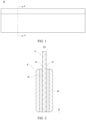
- FIG. 1 is a schematic structural diagram of a positive electrode plate according to some embodiments of this application
- FIG. 2 is a sectional view of the positive electrode plate shown in FIG. 1 and sectioned along a line A-A.
- a positive electrode plate 50 according to an embodiment of this application includes a positive current collector 51 and a positive active material layer 52 disposed on at least one surface 511 of the positive current collector 51.
- the positive current collector 51 includes two surfaces 511 opposite to each other in a thickness direction X of the positive current collector.
- the positive active material layer 52 is disposed on any one of the two surfaces 511 of the positive current collector 51, or on both surfaces 511 separately.
- the direction X shown in FIG. 1 is a thickness direction of the positive current collector 51.
- the positive current collector 51 may be made of a metal or may be a composite current collector.
- the positive current collector may be a metal foil or a porous metal sheet such as aluminum or an aluminum alloy.
- the positive current collector 51 is made of an aluminum foil.
- the positive current collector may include a polymer material substrate and a metal layer formed on at least one surface 511 of the polymer material substrate.
- the composite current collector may be formed by overlaying the polymer material substrate with a metal material (for example, aluminum, aluminum alloy, nickel, nickel alloy, titanium, titanium alloy, silver, or silver alloy).
- the polymer material substrate may be, for example, polypropylene (PP), polyethylene terephthalate (PET), polybutylene terephthalate (PBT), polystyrene (PS), or polyethylene (PE).
- the positive active material layer 52 includes a positive active material.
- the positive active material is a lithium iron phosphate active material. This material enables reversible deintercalation and intercalation of lithium ions and transfer of electrons during charge-and-discharge cycles.
- the positive current collector 51 collects and outputs current.
- a ferrous ion in a lithium iron phosphate particle is located at a 4c site of an oxygen octahedron, and a lithium ion is located at a 4a site of the oxygen octahedron.
- the structure of a polyanion phosphate ion is of relatively high thermal stability.
- FeO 6 octahedra are separated by oxygen atoms in tetrahedral phosphate ions and thereby fail to form a continuous FeO 6 network, resulting in a relatively low electronic conductivity of the lithium iron phosphate particles.
- a diffusion coefficient of lithium ions in the lithium iron phosphate particles is relatively low.
- the low electrical conductivity and low lithium-ion diffusion coefficient of the lithium iron phosphate particles result in relatively low rate performance of the material that adopts such lithium iron phosphate particles.
- the carbon layer has the advantages of high electrical conductivity and a large specific surface area.
- the inventor hereof attempts to coat the surface of the lithium iron phosphate particle with a carbon layer to form a graphitized lithium iron phosphate particle, so as to build a good conductive network on the surface of the lithium iron phosphate particle, and in turn, improve the conductivity of the positive electrode plate 50.
- the inventor hereof finds that in order to improve the conductivity of the positive electrode sheet, because the graphitization degree of the lithium iron phosphate particle is relatively high, the lithium iron phosphate particle with a relatively high graphitization degree increases the difficulty of forming a positive active material layer by coating, and is adverse to thick coating processing.
- the positive active material layer 52 is divided into two layers.
- the positive active material layer 52 includes the first active material layer 521 and a second active material layer 522 that are sequentially stacked in a direction away from the surface 511 of the positive current collector 51.
- Both active material layers adopt graphitized lithium iron phosphate particles.
- the first active material layer 521 is disposed close to the surface 511 of the positive current collector 51, and the second active material layer 522 is disposed away from the surface 511 of the positive current collector 51.
- the first active material layer 521 includes a first composite particle.
- the first composite particle includes a first lithium iron phosphate particle and a first carbon layer that coats a surface 511 of the first lithium iron phosphate particle.
- the second active material layer 522 includes a second composite particle.
- the second composite particle includes a second lithium iron phosphate particle and a second carbon layer that coats a surface 511 of the second lithium iron phosphate particle.
- Each layer can improve conductivity, and can significantly improve a contact resistance between the entire positive active material layer 52 and the positive current collector 51, thereby improving conductivity, and in turn, improving the rate performance of a secondary battery that adopts the positive active material layer 52.
- graphitization degree herein means a degree to which carbon atoms form a close-packed hexagonal graphite crystal structure. The closer the lattice size is to the lattice parameters of ideal graphite, the higher the graphitization degree.
- the graphitization degree herein is used to characterize the carbon coating layer of lithium iron phosphate.
- the graphitization degree varies between the two active material layers.
- the graphitization degree of the first composite particle of the first active material layer 521 is higher than the graphitization degree of the second composite particle of the second active material layer 522.
- the first composite particle is of a higher graphitization degree, and is less compatible with the solvent, such as N-methyl-pyrrolidone NMP, in the slurry, and is less dispersible.
- the solid content in the slurry configured to prepare the first active material layer 521 is relatively lower.
- the graphitization degree of the lithium iron phosphate particle is relatively high, the particles can slip easily against each other, thereby enhancing the flexibility of the positive electrode plate 50 and reducing the risk of corner cracking during winding of the electrode assembly.
- the graphitization degree of the second composite particle is relatively low. Therefore, the second composite particle is more compatible with the solvent, such as N-methyl-pyrrolidone NMP, and is highly dispersible.
- the solid content in the slurry configured to prepare the second active material layer 522 is relatively higher. Due to the difference in solid content, a gradient difference in solvent concentration can be formed between the slurry configured to prepare the first active material layer 521 and the slurry configured to prepare the second active material layer 522, thereby facilitating thick coating of the positive active material layer 52, and in turn, increasing the energy density of the secondary battery.
- the positive electrode plate 50 includes two active material layers, and each active material layer includes a carbon-layer-coated lithium iron phosphate particle.
- the carbon layer is of relatively high conductivity, and can significantly improve conductivity of the active material layer and significantly improve a contact resistance between the positive active material layer 52 and the positive current collector 51, thereby improving conductivity of the positive electrode plate 50, and in turn, improving the rate performance of a secondary battery that adopts the positive electrode plate 50.
- the two active material layers are a first active material layer 521 and a second active material layer 522 respectively. The first active material layer 521 is disposed closer to the positive current collector 51.
- the graphitization degree of the first active material layer 521 is relatively higher, and a solid content of a slurry configured to prepare the first active material layer 521 is relatively low.
- the second active material layer 522 is disposed away from the positive current collector 51.
- the graphitization degree of the second active material layer 522 is relatively low, and a solid content of a slurry configured to prepare the second active material layer 522 is relatively high.
- the difference between the solid content of the slurry configured to prepare the first active material layer 521 and the solid content of the slurry configured to prepare the second active material layer 522 results in a gradient difference in solvent concentration.
- the joint use of the two active material layers facilitates thick coating of the positive active material layer 52, and in turn, increase the energy density of the secondary battery that adopts the positive electrode plate 50.
- the positive electrode plate 50 enables the secondary battery to achieve a good trade-off between relatively high rate performance, a relatively high energy density, and high overall electrochemical performance.
- the graphitization degree of the first composite particle is 0.3 to 0.6.
- a lower limit of the graphitization degree of the first composite particle may be 0.3, 0.4, or 0.5.
- An upper limit of the graphitization degree of the first composite particle may be 0.6, 0.5, or 0.4.
- the range of the graphitization degree of the first composite particle may be a reasonable combination of any upper limit and any lower limit mentioned above.
- the graphitization degree of the first composite particle is 0.3 to 0.5.
- the relatively high graphitization degree of the first composite particle further improves the conductivity of the first active material layer 521, and the solid content of the slurry containing the first composite particle is relatively low.
- the graphitization degree of the second composite particle is 0.05 to 0.3.
- a lower limit of the graphitization degree of the second composite particle may be 0.05, 0.1, 0.15, 0.2, 0.25, or the like.
- An upper limit of the graphitization degree of the second composite particle may be 0.15, 0.20, 0.25, 0.30, or the like.
- the range of the graphitization degree of the second composite particle may be a reasonable combination of any upper limit and any lower limit mentioned above.
- the graphitization degree of the second composite particle is 0.1 to 0.2.
- the relatively low graphitization degree of the second composite particle increases the solid content in the slurry configured to prepare the second active material layer 522.
- the slurry with a low solid content and the slurry with a high solid content are used jointly to further reduce the difficulty of thick coating and increase the thickness of the positive active material layer 52.
- the contact area between the composite particle and the electrolytic solution is excessively large.
- the electrolytic solution is prone to side reactions on the surface 511 of the composite particle, thereby aggravating gas production, increasing the generated heat, and deteriorating the safety performance and cycle performance of the secondary battery.
- the average particle diameter of the composite particles is excessively large or the specific surface area is excessively low, the path for intercalation and deintercalation of lithium ions in the composite particle during charge-and-discharge cycles is excessively long, and the kinetic performance of the secondary battery is impaired.
- the average particle diameter D 50 and/or specific surface area of the composite particles is controlled to fall within appropriate ranges to improve the performance of the secondary battery.
- D v50 also known as a median diameter, is a particle diameter of a material measured when the cumulative volume percent of the specimen particles of the material reaches 50% in a volume-based particle size distribution.
- the value of D 50 may be measured by a laser diffraction particle size analyzer (such as Malvern Mastersizer 3000).
- the first composite particle includes a primary particle.
- the second composite particle includes a secondary particle formed by aggregating a plurality of primary particles.
- An average particle diameter D 50 of the first composite particle is less than an average particle diameter D 50 of the second composite particle.
- the difference in particle size between the second composite particle and the first composite particle can form a porous structure, thereby improving kinetic performance of the secondary battery.
- the average particle diameter D 50 of the first composite particle is 1 ⁇ m to 4 ⁇ m.
- a lower limit of the average particle diameter D 50 of the first composite particle may be 1 ⁇ m, 2 ⁇ m, 3 ⁇ m, or the like.
- An upper limit of the average particle diameter D 50 of the first composite particle may be 2 ⁇ m, 3 ⁇ m, 4 ⁇ m, or the like.
- the range of the average particle diameter D 50 of the first composite particle may be a reasonable combination of any upper limit and any lower limit mentioned above, and optionally, may be 1 ⁇ m to 3 ⁇ m.
- the first composite particle with a particle diameter falling within the foregoing range can increase the area of contacting the electrolytic solution, and improve the rate performance of the secondary battery; and, during formation of the first active material layer 521, can increase the compaction density, and in turn, increase the energy density of the secondary battery.
- the average particle diameter D 50 of the second composite particle is 6 ⁇ m to 12 ⁇ m.
- the lower limit of the average particle diameter D 50 of the second composite particle may be 6 ⁇ m, 7 ⁇ m, 8 ⁇ m, 9 ⁇ m, 10 ⁇ m, or 11 ⁇ m.
- the upper limit of the average particle diameter D 50 of the second composite particle may be 7 ⁇ m, 8 ⁇ m, 9 ⁇ m, 10 ⁇ m, 11 ⁇ m, or 12 ⁇ m.
- the range of the average particle diameter D 50 of the second composite particle may be a reasonable combination of any upper limit and any lower limit mentioned above, and optionally, may be 8 ⁇ m to 10 ⁇ m.
- the slurry is not prone to phenomena such as agglomeration when being made into the second active material layer 522, and the relatively large average particle diameter D 50 of the second composite particle can significantly enhance the rate performance of the secondary battery.
- the second composite particle is of a spherical or quasi-spherical morphology.
- a specific surface area of this morphology is relatively large, thereby increasing a contact area between the second composite particle and an electrolytic solution, facilitating the electrolytic solution in infiltrating the second composite particle, and in turn, improving transfer performance of lithium ions, and enhancing the rate performance of the secondary battery.
- the specific surface area of the first composite particle is 10 m 2 /g to 15 m 2 /g.
- a lower limit of the specific surface area of the first composite particle is 10 m 2 /g, 11 m 2 /g, 12 m 2 /g, or 13 m 2 /g.
- An upper limit of the specific surface area of the first composite particles is 11 m 2 /g, 12 m 2 /g, 13 m 2 /g, 14 m 2 /g, 15 m 2 /g, or the like.
- the range of the specific surface area of the first composite particle may be a reasonable combination of any upper limit and any lower limit mentioned above, and optionally, may be 12 m 2 /g to 14 m 2 /g.
- the specific surface area of the first composite particle is relatively large, and the particles are dispersed evenly, thereby improving the effect of infiltrating the first composite particle by the electrolytic solution.
- the specific surface area of the second composite particle is 5 m 2 /g to 10 m 2 /g.
- a lower limit of the specific surface area of the second composite particle is 5 m 2 /g, 6 m 2 /g, or 7 m 2 /g.
- An upper limit of the specific surface area of the second composite particles is 7 m 2 /g, 8 m 2 /g, 9 m 2 /g, 10 m 2 /g, or the like.
- the range of the specific surface area of the second composite particle may be a reasonable combination of any upper limit and any lower limit mentioned above, and optionally, may be 6 m 2 /g to 8 m 2 /g.
- the second composite particles have a relatively small specific surface area and a relatively large particle diameter, and form a relatively large number of voids after being packed.
- a void gradient difference can be formed between the first active material layer 521 and the second active material layer 522, thereby facilitating transfer of lithium ions and improving the kinetic performance.
- a ratio of a coating weight CW1 of the first active material layer 521 to a coating weight CW2 of the second active material layer 522 is 0.8 to 1.2.
- a lower limit of the ratio may be 0.8, 0.9, 1.0 or 1.1, and an upper limit of the ratio may be 0.9, 1.0, 1.1, or 1.2.
- the range of the ratio may be a reasonable combination of any upper limit and any lower limit mentioned above.
- the ratio of the coating weight CW1 of the first active material layer 521 to the coating weight CW2 of the second active material layer 522 is 1.
- the coating weight CW1 of the first active material layer 521 satisfies 0.115 mg/cm 2 ⁇ CW1 ⁇ 0.195 mg/cm 2 .
- a lower limit of CW1 may be 0.115 mg/cm 2 , 0.120 mg/cm 2 , 0.125 mg/cm 2 , 0.130 mg/cm 2 , 0.135 mg/cm 2 , 0.140 mg/cm 2 , 0.145 mg/cm 2 , 0.150 mg/cm 2 , 0.155 mg/cm 2 , 0.160 mg/cm 2 , 0.165 mg/cm 2 , 0.170 mg/cm 2 , 0.175 mg/cm 2 , or 0.180 mg/cm 2 .
- An upper limit of CW1 may be 0.125 mg/cm 2 , 0.130 mg/cm 2 , 0.135 mg/cm 2 , 0.140 mg/cm 2 , 0.145 mg/cm 2 , 0.150 mg/cm 2 , 0.155 mg/cm 2 , 0.160 mg/cm 2 , 0.165 mg/cm 2 , 0.170 mg/cm 2 , 0.175 mg/cm 2 , 0.180 mg/cm 2 , 0.185 mg/cm 2 , 0.190 mg/cm 2 , or 0.195 mg/cm 2 .
- the range of CW1 may be a reasonable combination of any upper limit and any lower limit mentioned above.
- the coating weight CW2 of the second active material layer 522 satisfies 0.115 mg/cm 2 ⁇ CW2 ⁇ 0.195 mg/cm 2 .
- a lower limit of CW2 may be 0.115 mg/cm 2 , 0.120 mg/cm 2 , 0.125 mg/cm 2 , 0.130 mg/cm 2 , 0.135 mg/cm 2 , 0.140 mg/cm 2 , 0.145 mg/cm 2 , 0.150 mg/cm 2 , 0.155 mg/cm 2 , 0.160 mg/cm 2 , 0.165 mg/cm 2 , 0.170 mg/cm 2 , 0.175 mg/cm 2 , or 0.180 mg/cm 2 .
- An upper limit of CW2 may be 0.125 mg/cm 2 , 0.130 mg/cm 2 , 0.135 mg/cm 2 , 0.140 mg/cm 2 , 0.145 mg/cm 2 , 0.150 mg/cm 2 , 0.155 mg/cm 2 , 0.160 mg/cm 2 , 0.165 mg/cm 2 , 0.170 mg/cm 2 , 0.175 mg/cm 2 , 0.180 mg/cm 2 , 0.185 mg/cm 2 , 0.190 mg/cm 2 , or 0.195 mg/cm 2 .
- the range of CW2 may be a reasonable combination of any upper limit and any lower limit mentioned above.
- the first active material layer 521 and the second active material layer 522 coordinate with each other to increase the overall coating weight of the positive active material.
- a powder compaction density of the first active material layer 521 under a pressure of 600 MPa is 2.4 g/cc to 2.65 g/cc.
- a lower limit of the powder compaction density of the first active material layer 521 under a pressure of 600 MPa may be 2.4 g/cc, 2.45 g/cc, 2.50 g/cc, or 2.55 g/cc.
- An upper limit of the powder compaction density of the first active material layer 521 under a pressure of 600 MPa may be 2.45 g/cc, 2.50 g /cc, 2.55 g/cc, 2.60 g/cc, or 2.65 g/cc.
- the range of the powder compaction density may be a reasonable combination of any upper limit and any lower limit mentioned above, and optionally, may be 2.5 g/cc to 2.6 g/cc.
- the first active material layer 521 with a powder compaction density falling within the foregoing range increases the energy density of the secondary battery due to a relatively high compaction density.
- a powder compaction density of the second active material layer 522 under a pressure of 600 MPa is 2.2 g/cc to 2.45 g/cc.
- a lower limit of the powder compaction density of the second active material layer 522 under a pressure of 600 MPa may be 2.2 g/cc, 2.25 g/cc, 2.30 g/cc, or 2.35 g/cc.
- An upper limit of the powder compaction density of the second active material layer 522 under a pressure of 600 MPa may be 2.30 g/cc, 2.35 g/cc, 2.40 g/cc, or 2.45 g/cc.
- the range of the powder compaction density may be a reasonable combination of any upper limit and any lower limit mentioned above, and optionally, may be 2.35 g/cc to 2.45 g/cc.
- the powder compaction density of the second active material layer 522 falls with the foregoing range, the powder compaction density of the second active material layer 522 is relatively low, and the particles in the slurry configured to prepare the second active material layer 522 are excellent in fluidity, dispersivity, and processability.
- the particles in the second active material layer 522 are of relatively high fluidity and can be dispersed uniformly, and, when used together with the slurry configured to prepare the first active material layer 521, facilitate preparation of the positive active material layer 52, and improve the quality of the positive electrode plate.
- the first active material layer 521 and the second active material layer 522 coordinate with each other in terms of the powder compaction density to increase the overall compaction density of the positive active material layer 52, and in turn, increase the energy density of the secondary battery.
- the positive active material layer 52 further optionally includes a conductive agent.
- the conductive agent is not particularly limited, and may be a conductive agent well known in the art.
- the conductive agent may include at least one of superconductive carbon, acetylene black, carbon black, Ketjen black, carbon dots, carbon nanotubes, graphene, or carbon nanofibers.
- the conductive agent can reduce the internal resistance of the positive active material layer 52 and increase the electrical conductivity between the positive active material layer 52 and the positive current collector 51.
- the carbon-coated lithium iron phosphate particles can improve the electrical conductivity of the positive active material layer 52 to some extent, and in turn, reduce the dosage of the conductive agent to some extent and relatively increase the dosage of the lithium iron phosphate particles, thereby improving the utilization rate of the positive active material, achieving a low resistance of electrode plates, and increasing the energy density of the secondary battery.
- the first active material layer 521 includes a first conductive agent. On a basis that a total weight of the first active material layer 521 is 100%, a mass percent of the first conductive agent is A.
- the second active material layer 522 includes a second conductive agent, and, on a basis that a total weight of the second active material layer 522 is 100%, a mass percent of the second conductive agent is B, where A ⁇ B, and optionally 1 wt% ⁇ B - A ⁇ 3 wt%.
- the graphitization degree of the first active material layer 521 is relatively higher.
- the dosage of the conductive agent in the first active material layer 521 can be reduced, and the mass percent of the first composite particle can be increased, thereby increasing the energy density of the secondary battery.
- the positive active material layer 52 further optionally includes a binder.
- the binder is not particularly limited, and may be a binder well known in the art.
- the binder may include one or more of styrene-butadiene rubber (SBR), water-based acrylic resin (water-based acrylic resin), carboxymethyl cellulose (CMC), polyvinylidene difluoride (PVDF), polytetrafluoroethylene (PTFE), poly(ethylene-co-vinyl acetate) (EVA), or polyvinyl alcohol (PVA).
- SBR styrene-butadiene rubber
- water-based acrylic resin water-based acrylic resin
- CMC carboxymethyl cellulose
- PVDF polyvinylidene difluoride
- PTFE polytetrafluoroethylene
- EVA poly(ethylene-co-vinyl acetate)
- PVA polyvinyl alcohol
- the binder is configured to bind the composite particles to the conductive agent to ensure that a conductive network inside the positive electrode plate 50 is of high structural stability. Due to the low conductivity of the binder itself, the dosage of the binder may be relatively small, so as to achieve a low resistance of electrode plates.
- an embodiment of this application further provides a method for preparing a positive electrode plate.
- the positive electrode plate according to this embodiment of this application may be prepared by coating.
- An illustrative preparation method is: coating at least one surface of the positive current collector with a first positive slurry to obtain a first active material layer; coating a surface of the first active material layer with the second positive slurry, where the surface is oriented away from the positive current collector, so as to obtain a second active material layer; and subsequently, performing steps such as drying and cold calendering on the first active material layer and the second active material layer to form a positive active material layer on the positive current collector, so as to obtain a positive electrode plate.
- the method for preparing the positive electrode plate includes the following steps:
- an embodiment of this application further provides a secondary battery.
- FIG. 3 is a schematic structural diagram of an electrode assembly of a secondary battery according to some embodiments of this application
- FIG. 4 is a schematic exploded view of a secondary battery according to some embodiments of this application.
- the secondary battery according to this embodiment of this application includes a positive electrode plate 50, a negative electrode plate 60, a separator 70, and an electrolytic solution.
- the positive electrode plate 50 is the positive electrode plate according to the first aspect of this application, or a positive electrode plate prepared by the preparation method according to the second aspect of this application.
- the secondary battery according to this application achieves both relatively high rate performance and a relatively high energy density.
- the negative electrode plate 60 may be a metal lithium sheet; or, may include a negative current collector and a negative active material layer disposed on at least one surface of the negative current collector.
- the negative active material layer includes a negative active material.
- the negative current collector is a copper foil.
- the negative active material in the negative active material layer may be a negative active material that is well known in the art for use in a secondary battery.
- the negative active material may include at least one of the following materials: artificial graphite, natural graphite, soft carbon, hard carbon, silicon-based material, tin-based material, lithium titanium oxide, and the like.
- the silicon-based material may be at least one selected from simple-substance silicon, a silicon-oxygen compound, a silicon-carbon composite, a silicon-nitrogen composite, and a silicon alloy.
- the tin-based material may be at least one selected from simple-substance tin, a tin-oxygen compound, or a tin alloy.
- this application is not limited to such materials, and other conventional materials usable as a negative active material of a battery may be used instead.
- One of the negative active materials may be used alone, or at least two thereof may be used in combination.
- the negative active material layer further optionally includes a binder.
- the binder may be at least one selected from styrene-butadiene rubber (SBR), polyacrylic acid (PAA), polyacrylic acid sodium (PAAS), polyacrylamide (PAM), polyvinyl alcohol (PVA), sodium alginate (SA), polymethyl acrylic acid (PMAA), and carboxymethyl chitosan (CMCS).
- the negative active material layer further optionally includes a conductive agent.
- the conductive agent may be at least one selected from superconductive carbon, acetylene black, carbon black, Ketjen black, carbon dots, carbon nanotubes, graphene, or carbon nanofibers.
- the negative active material layer further optionally includes other agents, such as a thickener (for example, sodium carboxymethyl cellulose (CMC-Na)).
- a thickener for example, sodium carboxymethyl cellulose (CMC-Na)
- the negative electrode plate 60 may be prepared according to the following method: dispersing the ingredients of the negative electrode plate 60 such as the negative active material, the conductive agent, and the binder and any other ingredients in a solvent (such as deionized water) to form a negative slurry, coating a negative current collector with the negative slurry, and performing steps such as drying and cold calendering to obtain the negative electrode plate 60.
- a solvent such as deionized water
- the type of the separator 70 is not particularly limited in this application, and may be any well-known porous separator 70 that is highly stable both chemically and mechanically.
- the separator 70 may be made of a material that is at least one selected from glass fiber, non-woven fabric, polyethylene, polypropylene, or polyvinylidene difluoride.
- the separator 70 may be a single-layer film or a multilayer composite film, without being particularly limited. When the separator 70 is a multilayer composite film, materials in different layers may be identical or different, without being particularly limited.
- the positive electrode plate 50, the negative electrode plate 60, and the separator 70 may be made into an electrode assembly 40 by winding or stacking.
- the electrode assembly 40 shown in FIG. 3 is jell-roll electrode assembly.
- the electrolyte serves to conduct ions between the positive electrode plate 50 and the negative electrode plate 60.
- the type of the electrolyte is not particularly limited in this application, and may be selected as required.
- the electrolyte may be in a liquid state or gel state, or all solid state.
- the electrolyte is an electrolytic solution.
- the electrolytic solution includes an electrolyte salt and a solvent.
- the electrolyte salt may be at least one selected from lithium hexafluorophosphate, lithium tetrafluoroborate, lithium perchlorate, lithium hexafluoroarsenate, lithium bisfluorosulfonimide, lithium bistrifluoromethanesulfonimide, lithium trifluoromethanesulfonate, lithium difluorophosphate, lithium difluoro(oxalato)borate, lithium bis(oxalato)borate, lithium difluoro(bisoxalato)phosphate, and lithium tetrafluoro(oxalato)phosphate.
- the solvent may be at least one selected from ethylene carbonate, propylene carbonate, ethyl methyl carbonate, diethyl carbonate, dimethyl carbonate, dipropyl carbonate, methyl propyl carbonate, ethylene propyl carbonate, butylene carbonate, fluoroethylene carbonate, methyl formate, methyl acetate, ethyl acetate, propyl acetate, methyl propionate, ethyl propionate, propyl propionate, methyl butyrate, ethyl butyrate, 1,4-butyrolactone, sulfolane, methyl sulfonyl methane, ethyl methyl sulfone, and (ethylsulfonyl)ethane.
- the electrolytic solution further optionally includes an additive.
- the additive may include a negative film-forming additive or a positive film-forming additive.
- the additive may further include an additive capable of improving specified performance of the battery, for example, an additive for improving overcharge performance of the battery, or an additive for improving high- or low-temperature performance of the battery.
- the secondary battery 30 includes a cap assembly 31, a housing 32, and an electrode assembly 40 and an electrolytic solution that are accommodated in the housing 32.
- the electrode assembly 40 includes a positive electrode plate 50, a negative electrode plate 60, and a separator 70.
- the positive electrode plate 50 or the negative electrode plate 60 includes a tab.
- the electrolyte serves to conduct ions between the positive electrode plate 50 and the negative electrode plate 60.
- the separator 70 primarily serves to prevent a short circuit between the positive electrode plate 50 and the negative electrode plate 60 while allowing passage of ions.
- the secondary battery 30 may be a jelly-roll or stacked battery, exemplarily but without being limited to, one of a lithium-ion secondary battery, a lithium primary battery, a sodium-ion battery, or a magnesium-ion battery.
- the housing 32 of the secondary battery may be a hard shell such as a hard plastic shell, an aluminum shell, a steel shell, or the like.
- the housing 32 of the secondary battery may be a soft package such as a pouch-type soft package.
- the soft package may be made of plastic such as polypropylene, polybutylene terephthalate, or polybutylene succinate.
- the secondary battery may be assembled to form a battery module.
- the battery module may include one or more secondary batteries, and the specific number of secondary batteries in a battery module may be selected by a person skilled in the art depending on practical applications and capacity of the battery module.
- FIG. 5 is a schematic structural diagram of a battery module according to some embodiments of this application.
- a plurality of secondary batteries 30 may be arranged sequentially along a length direction of the battery module 20.
- the secondary batteries may be arranged in any other manner.
- the plurality of secondary batteries 30 may be fixed by a fastener.
- the battery module 20 may further include a shell that provides an accommodation space.
- the plurality of secondary batteries 30 are accommodated in the accommodation space.
- the battery module may be assembled to form a battery pack.
- the battery pack may include one or more battery modules, and the specific number of battery modules in a battery pack may be selected by a person skilled in the art depending on practical applications and capacity of the battery pack.
- FIG. 6 is a schematic structural diagram of a battery pack according to some embodiments of this application.
- the battery pack 10 may contain a battery box and a plurality of battery modules 20 disposed in the battery box.
- the battery box includes an upper box 12 and a lower box 11.
- the upper box 12 fits the lower box 11 to form a closed space for accommodating the battery modules 20.
- the plurality of battery modules 20 may be arranged in the battery box in any manner.
- the electrical device includes at least one of the secondary battery, the battery module, or the battery pack according to this application.
- the secondary battery, the battery module, or the battery pack may be used as a power supply of the electrical device, or used as an energy storage unit of the electrical device.
- the electrical device may include, but without being limited to, a mobile device (such as a mobile phone or a laptop computer), an electric vehicle (such as a battery electric vehicle, a hybrid electric vehicle, a plug-in hybrid electric vehicle, an electric bicycle, an electric scooter, an electric golf cart, or an electric truck), an electric train, a ship, a satellite system, or an energy storage system.
- the secondary battery, the battery module, or the battery pack may be selected for use in the electrical device according to practical requirements of the electrical device.
- FIG. 7 is a schematic structural diagram of an electrical device according to some embodiments of this application.
- the electrical device 1 includes a secondary battery 30.
- the electrical device 1 may be battery electric vehicle, a hybrid electric vehicle, a plug-in hybrid electric vehicle, or the like.
- the electrical device may adopt a battery pack or a battery module in order to meet the requirements of the electrical device 1 on a high power and a high energy density of the secondary battery 30.
- the device may be a mobile phone, a tablet computer, a notebook computer, or the like.
- the device is generally required to be thin and light, and may have a secondary battery as a power supply.
- the secondary batteries in Embodiments 1 to 35 and Comparative Embodiments 1 to 4 are prepared by using the following method:
- the positive current collector is an aluminum foil that is 13 ⁇ m thick.
- the first composite particle are graphitized olivine-structured lithium iron phosphate.
- the first composite particles are graphitized olivine-structured lithium iron phosphate.
- first positive slurry and the second positive slurry onto an aluminum foil by a double-sided double-chamber applicator. Performing steps of drying, cold calendering, and slitting to make a positive electrode plate. In applying the slurry, the first positive slurry is located between the second positive slurry and the aluminum foil.
- the negative current collector is a copper foil that is 6 ⁇ m thick.
- the separator is a PP film.
- EC ethylene carbonate
- EMC ethyl methyl carbonate
- Test Pouring the specimen into a specimen in-feed tower so that the specimen is circulated to a testing optical path system along with the solution. Irradiating the particles with a laser beam, receiving diffused light, and measuring energy distribution of the diffused light to obtain particle size distribution characteristics of the particles (shading degree: 8% to 12%). Specifically, the specimen may be measured based on the standard GB/T19077-2016/ISO 13320:2009.
- test steps are as follows:
- Discharge capacity retention rate of lithium ⁇ ion secondary battery discharged at a 1 C rate % discharge capacity of the battery discharged at a 1 C rate / discharge capacity of the battery discharged at a 0.33 C rate ⁇ 100 % .
- Table 1 and Table 2 show the parameters of Embodiments 1 to 27 and Comparative Embodiments 1 to 3.
- Table 1 First active material layer Graphitization degree D 50 of first composite particle ( ⁇ m) BET specific surface area of first composite particle (m 2 /g) CW1 of first composite particle (mg/cm 2 ) Mass percent of first composite particle (%) Mass percent A of first conductive agent (%) Compaction density (g/cc) Embodiment 1 0.2 2 13 0.175 96 1 2.5 Embodiment 2 0.3 2 13 0.175 96 1 2.5 Embodiment 3 0.4 2 13 0.175 96 1 2.5 Embodiment 4 0.5 2 13 0.175 96 1 2.5 Embodiment 5 0.6 2 13 0.175 96 1 2.5 Embodiment 6 0.8 2 13 0.175 96 1 2.5 Embodiment 7 0.4 2 13 0.115 96 1 2.5 Embodiment 8 0.4 2 13 0.155 96 1 2.5 Embodiment 9 0.4 2 13 0.175 96 1 2.5 Embodiment
- Table 3 shows the test results of Embodiments 1 to 27 and Comparative Embodiments 1 to 4.
- Comparative Embodiment 1 adopts one graphitized positive active material layer, and therefore, achieves relatively good rate performance.
- Embodiments 1 to 27 have increased the energy density significantly. Therefore, the secondary batteries of Embodiments 1 to 27 can achieve a good trade-off between rate performance and energy density.
- the graphitization degree of the first active material layer and the second active material layer in Embodiments 1 to 6 is relatively high, and therefore, the rate performance of the secondary battery is relatively high, and the direct-current resistance is relatively low. With the increase of the graphitization degree, the rate performance is higher. In addition, the rate performance and the energy density in Embodiment 3 are relatively high.
- the mass percent of the graphitized first active material layer contained in the secondary battery is relatively high, and therefore, the rate performance is relatively high, and the direct-current resistance is relatively low.
- the energy density of the secondary battery is increased.
- Embodiments 12 to 15 on the basis of adopting the first active material layer with a relatively high graphitization degree, the mass percent of the conductive agent in the first active material layer is reduced. Therefore, the energy density is increased without noticeably deteriorating the rate performance.
- Embodiments 16 to 21 to the extent that the compaction density is in a reasonable range, the increase of the compaction density of the first active material layer leads to increase of the energy density of the secondary battery, and also leads to improvement of the rate performance.
- Embodiments 22 to 27 to the extent that the compaction density is in a reasonable range, the increase of the compaction density of the second active material layer leads to increase of the energy density of the secondary battery, and also leads to improvement of the rate performance.
- FIG. 8 is a transmission electron microscope (TEM) image of a first composite particle according to Embodiment 1;
- FIG. 9 is a TEM image of a second composite particle according to Embodiment 1;
- FIG. 10 is a local scanning electron microscope (SEM) image of a positive electrode plate according to Embodiment 1.
- TEM transmission electron microscope
- SEM local scanning electron microscope
Landscapes
- Chemical & Material Sciences (AREA)
- Chemical Kinetics & Catalysis (AREA)
- Electrochemistry (AREA)
- General Chemical & Material Sciences (AREA)
- Engineering & Computer Science (AREA)
- Composite Materials (AREA)
- Inorganic Chemistry (AREA)
- Materials Engineering (AREA)
- Crystallography & Structural Chemistry (AREA)
- Aviation & Aerospace Engineering (AREA)
- Manufacturing & Machinery (AREA)
- Battery Electrode And Active Subsutance (AREA)
Applications Claiming Priority (1)
| Application Number | Priority Date | Filing Date | Title |
|---|---|---|---|
| PCT/CN2022/072148 WO2023133844A1 (zh) | 2022-01-14 | 2022-01-14 | 正极极片、二次电池、电池模块、电池包和用电装置 |
Publications (2)
| Publication Number | Publication Date |
|---|---|
| EP4239717A1 true EP4239717A1 (de) | 2023-09-06 |
| EP4239717A4 EP4239717A4 (de) | 2025-04-30 |
Family
ID=87279853
Family Applications (1)
| Application Number | Title | Priority Date | Filing Date |
|---|---|---|---|
| EP22896848.3A Pending EP4239717A4 (de) | 2022-01-14 | 2022-01-14 | Positivelektrodenplatte, sekundärbatterie, batteriemodul, batteriepack und elektrische vorrichtung |
Country Status (4)
| Country | Link |
|---|---|
| US (2) | US12062783B2 (de) |
| EP (1) | EP4239717A4 (de) |
| CN (1) | CN117083729A (de) |
| WO (1) | WO2023133844A1 (de) |
Families Citing this family (8)
| Publication number | Priority date | Publication date | Assignee | Title |
|---|---|---|---|---|
| CN117133913B (zh) * | 2023-08-25 | 2026-03-31 | 上海量孚新能源科技有限公司 | 磷酸铁锂前驱体、磷酸铁锂材料及其制备方法和应用 |
| CN119852323A (zh) * | 2024-01-08 | 2025-04-18 | 宁德时代新能源科技股份有限公司 | 正极极片、二次电池和用电装置 |
| CN119852305B (zh) * | 2024-02-07 | 2025-11-04 | 宁德时代新能源科技股份有限公司 | 正极极片、二次电池和用电装置 |
| CN118206091B (zh) * | 2024-02-07 | 2025-08-26 | 宜宾天原科创设计有限公司 | 一种钠电石墨化碳包覆铁系磷酸盐正极材料的制备方法 |
| CN118231567A (zh) * | 2024-04-02 | 2024-06-21 | 湖北亿纬动力有限公司 | 一种正极极片及应用其的锂离子电池 |
| CN118588878B (zh) * | 2024-08-02 | 2024-11-19 | 比亚迪股份有限公司 | 一种正极片及电池 |
| CN119965220A (zh) * | 2025-01-03 | 2025-05-09 | 宁波维科电池有限公司 | 一种聚阴离子钠离子电池正极极片及其制备方法 |
| CN119905569B (zh) * | 2025-03-25 | 2025-07-18 | 深圳市贝特瑞纳米科技有限公司 | 正极材料及电池 |
Family Cites Families (12)
| Publication number | Priority date | Publication date | Assignee | Title |
|---|---|---|---|---|
| JP2010267540A (ja) * | 2009-05-15 | 2010-11-25 | Panasonic Corp | 非水電解質二次電池 |
| JP2015125832A (ja) * | 2013-12-25 | 2015-07-06 | トヨタ自動車株式会社 | 二次電池用電極の製造方法 |
| CN107742709A (zh) * | 2017-10-17 | 2018-02-27 | 中国科学院青岛生物能源与过程研究所 | 一种磷酸铁锂电池正极活性材料及其制备和应用 |
| CN115602789A (zh) * | 2019-03-01 | 2023-01-13 | 宁德时代新能源科技股份有限公司(Cn) | 负极片及二次电池 |
| CN110071292B (zh) * | 2019-04-04 | 2022-05-13 | 桑顿新能源科技(长沙)有限公司 | 一种锂离子电池正极极片的制备方法及其正极极片 |
| CN110474019B (zh) | 2019-07-08 | 2020-10-30 | 广州中国科学院工业技术研究院 | 一种高比能量电池正极极片及其制备方法 |
| KR102844350B1 (ko) * | 2019-10-14 | 2025-08-08 | 주식회사 엘지에너지솔루션 | 리튬 이차전지용 양극 활물질의 제조 방법 및 상기 방법에 의해 제조된 리튬 이차전지용 양극 활물질 |
| CN110581256B (zh) * | 2019-10-17 | 2020-12-18 | 泰州纳新新能源科技有限公司 | 一种磷酸铁锂正极的制备方法 |
| CN113330601A (zh) * | 2020-08-31 | 2021-08-31 | 宁德新能源科技有限公司 | 极片、电化学装置和电子装置 |
| CN113036085A (zh) | 2021-03-26 | 2021-06-25 | 湖北亿纬动力有限公司 | 一种正极极片及其制备方法和应用 |
| CN216213552U (zh) * | 2021-10-12 | 2022-04-05 | 厦门海辰新能源科技有限公司 | 一种极片和极片组件 |
| US20230111642A1 (en) * | 2021-10-12 | 2023-04-13 | Xiamen Hithium Energy Storage Technology Co., Ltd. | Electrode sheet and electrode sheet assembly |
-
2022
- 2022-01-14 WO PCT/CN2022/072148 patent/WO2023133844A1/zh not_active Ceased
- 2022-01-14 EP EP22896848.3A patent/EP4239717A4/de active Pending
- 2022-01-14 CN CN202280023692.4A patent/CN117083729A/zh active Pending
-
2023
- 2023-06-08 US US18/331,246 patent/US12062783B2/en active Active
-
2024
- 2024-07-01 US US18/760,121 patent/US20240356014A1/en active Pending
Also Published As
| Publication number | Publication date |
|---|---|
| WO2023133844A1 (zh) | 2023-07-20 |
| US20240356014A1 (en) | 2024-10-24 |
| US20230335722A1 (en) | 2023-10-19 |
| CN117083729A (zh) | 2023-11-17 |
| US12062783B2 (en) | 2024-08-13 |
| EP4239717A4 (de) | 2025-04-30 |
Similar Documents
| Publication | Publication Date | Title |
|---|---|---|
| EP4239717A1 (de) | Positivelektrodenplatte, sekundärbatterie, batteriemodul, batteriepack und elektrische vorrichtung | |
| EP4075538B1 (de) | Sekundärbatterie und herstellungsverfahren dafür sowie batteriemodul, batteriepack und vorrichtung mit der sekundärbatterie | |
| EP3926713B1 (de) | Sekundärbatterie, verfahren zu ihrer herstellung und diese sekundärbatterie enthaltende vorrichtung | |
| EP4170755A1 (de) | Positivelektrodenmaterial, positivelektrodenpolteil, lithiumsekundärbatterie, batteriemodul, batteriepack und vorrichtung | |
| US20230261175A1 (en) | Positive electrode active material and related electrode sheet, secondary battery, battery module, battery pack and apparatus thereof | |
| CN115832166B (zh) | 正极极片、二次电池、电池模块、电池包和用电装置 | |
| EP3926707A1 (de) | Sekundärbatterie, verfahren zu ihrer herstellung und diese enthaltende vorrichtung | |
| EP4228042A1 (de) | Sekundärbatterie und elektrische vorrichtung damit | |
| EP4451377A1 (de) | Sekundärbatterie, batteriemodul, batteriepack und elektrische vorrichtung | |
| EP4047712A1 (de) | Batteriesatz, batteriepack, elektrisches gerät sowie herstellungsverfahren und herstellungsvorrichtung für batteriesatz | |
| US20230127767A1 (en) | Separator, lithium-ion battery, battery module, battery pack, and electrical device | |
| EP4322259A1 (de) | Positivelektrodenmaterial, herstellungsverfahren dafür und sekundärbatterie damit | |
| EP4503173A1 (de) | Negativelektrodenplatte und herstellungsverfahren dafür, sekundärbatterie, batteriemodul, batteriepack und elektrische vorrichtung | |
| US20250079436A1 (en) | Secondary battery and electrical device | |
| US20250329720A1 (en) | Positive electrode sheet, battery, and electric device | |
| EP4611068A1 (de) | Batterie und elektrische vorrichtung | |
| EP4184616A1 (de) | Negatives silicium-kohlenstoff-elektrodenmaterial, negative elektrodenplatte, sekundärbatterie, batteriemodul, batteriepack und elektrische vorrichtung | |
| EP4513589A1 (de) | Sekundärbatterie und batteriemodul damit, batteriepack und elektrische vorrichtung | |
| EP4654281A1 (de) | Sekundärbatterie und elektrische vorrichtung | |
| US20250273663A1 (en) | Composite positive electrode material and preparation method thereof, positive electrode plate, secondary battery, and electric apparatus | |
| US20250260051A1 (en) | Gel electrolyte composition, secondary battery, battery module, battery pack, and electrical device | |
| EP4243120A1 (de) | Verbundstoff mit eigelbkernschalenstruktur, herstellungsverfahren dafür und sekundärbatterie damit | |
| EP4462496A1 (de) | Negativelektrodenplatte, verfahren zur herstellung davon, batteriezelle, batterie und elektrische vorrichtung | |
| EP4576245A1 (de) | Negativelektrodenfolie und herstellungsverfahren dafür, batteriezelle, batterie und elektrische vorrichtung | |
| EP4170746A1 (de) | Negativelektrodenaktivmaterial für eine sekundärbatterie mit wasserfreiem elektrolyt und sekundärbatterie mit wasserfreiem elektrolyt |
Legal Events
| Date | Code | Title | Description |
|---|---|---|---|
| STAA | Information on the status of an ep patent application or granted ep patent |
Free format text: STATUS: UNKNOWN |
|
| STAA | Information on the status of an ep patent application or granted ep patent |
Free format text: STATUS: THE INTERNATIONAL PUBLICATION HAS BEEN MADE |
|
| PUAI | Public reference made under article 153(3) epc to a published international application that has entered the european phase |
Free format text: ORIGINAL CODE: 0009012 |
|
| STAA | Information on the status of an ep patent application or granted ep patent |
Free format text: STATUS: REQUEST FOR EXAMINATION WAS MADE |
|
| 17P | Request for examination filed |
Effective date: 20230601 |
|
| AK | Designated contracting states |
Kind code of ref document: A1 Designated state(s): AL AT BE BG CH CY CZ DE DK EE ES FI FR GB GR HR HU IE IS IT LI LT LU LV MC MK MT NL NO PL PT RO RS SE SI SK SM TR |
|
| RAP1 | Party data changed (applicant data changed or rights of an application transferred) |
Owner name: CONTEMPORARY AMPEREX TECHNOLOGY(HONG KONG) LIMITED |
|
| DAV | Request for validation of the european patent (deleted) | ||
| DAX | Request for extension of the european patent (deleted) | ||
| A4 | Supplementary search report drawn up and despatched |
Effective date: 20250401 |
|
| RIC1 | Information provided on ipc code assigned before grant |
Ipc: H01M 4/62 20060101ALI20250326BHEP Ipc: H01M 4/36 20060101ALI20250326BHEP Ipc: H01M 4/04 20060101ALI20250326BHEP Ipc: H01M 10/0525 20100101ALI20250326BHEP Ipc: H01M 4/58 20100101ALI20250326BHEP Ipc: H01M 4/136 20100101AFI20250326BHEP |