EP4239734A1 - Dispositif de pile à combustible - Google Patents
Dispositif de pile à combustible Download PDFInfo
- Publication number
- EP4239734A1 EP4239734A1 EP21885745.6A EP21885745A EP4239734A1 EP 4239734 A1 EP4239734 A1 EP 4239734A1 EP 21885745 A EP21885745 A EP 21885745A EP 4239734 A1 EP4239734 A1 EP 4239734A1
- Authority
- EP
- European Patent Office
- Prior art keywords
- fuel cell
- electronic device
- controller
- user
- notification
- Prior art date
- Legal status (The legal status is an assumption and is not a legal conclusion. Google has not performed a legal analysis and makes no representation as to the accuracy of the status listed.)
- Pending
Links
Images


Classifications
-
- H—ELECTRICITY
- H01—ELECTRIC ELEMENTS
- H01M—PROCESSES OR MEANS, e.g. BATTERIES, FOR THE DIRECT CONVERSION OF CHEMICAL ENERGY INTO ELECTRICAL ENERGY
- H01M8/00—Fuel cells; Manufacture thereof
- H01M8/04—Auxiliary arrangements, e.g. for control of pressure or for circulation of fluids
- H01M8/04298—Processes for controlling fuel cells or fuel cell systems
- H01M8/04313—Processes for controlling fuel cells or fuel cell systems characterised by the detection or assessment of variables; characterised by the detection or assessment of failure or abnormal function
-
- F—MECHANICAL ENGINEERING; LIGHTING; HEATING; WEAPONS; BLASTING
- F24—HEATING; RANGES; VENTILATING
- F24D—DOMESTIC- OR SPACE-HEATING SYSTEMS, e.g. CENTRAL HEATING SYSTEMS; DOMESTIC HOT-WATER SUPPLY SYSTEMS; ELEMENTS OR COMPONENTS THEREFOR
- F24D17/00—Domestic hot-water supply systems
- F24D17/0005—Domestic hot-water supply systems using recuperation of waste heat
- F24D17/001—Domestic hot-water supply systems using recuperation of waste heat with accumulation of heated water
-
- F—MECHANICAL ENGINEERING; LIGHTING; HEATING; WEAPONS; BLASTING
- F24—HEATING; RANGES; VENTILATING
- F24D—DOMESTIC- OR SPACE-HEATING SYSTEMS, e.g. CENTRAL HEATING SYSTEMS; DOMESTIC HOT-WATER SUPPLY SYSTEMS; ELEMENTS OR COMPONENTS THEREFOR
- F24D19/00—Details
- F24D19/10—Arrangement or mounting of control or safety devices
- F24D19/1006—Arrangement or mounting of control or safety devices for water heating systems
- F24D19/1051—Arrangement or mounting of control or safety devices for water heating systems for domestic hot water
-
- F—MECHANICAL ENGINEERING; LIGHTING; HEATING; WEAPONS; BLASTING
- F24—HEATING; RANGES; VENTILATING
- F24H—FLUID HEATERS, e.g. WATER OR AIR HEATERS, HAVING HEAT-GENERATING MEANS, e.g. HEAT PUMPS, IN GENERAL
- F24H15/00—Control of fluid heaters
- F24H15/10—Control of fluid heaters characterised by the purpose of the control
- F24H15/16—Reducing cost using the price of energy, e.g. choosing or switching between different energy sources
-
- F—MECHANICAL ENGINEERING; LIGHTING; HEATING; WEAPONS; BLASTING
- F24—HEATING; RANGES; VENTILATING
- F24H—FLUID HEATERS, e.g. WATER OR AIR HEATERS, HAVING HEAT-GENERATING MEANS, e.g. HEAT PUMPS, IN GENERAL
- F24H15/00—Control of fluid heaters
- F24H15/20—Control of fluid heaters characterised by control inputs
- F24H15/277—Price
-
- F—MECHANICAL ENGINEERING; LIGHTING; HEATING; WEAPONS; BLASTING
- F24—HEATING; RANGES; VENTILATING
- F24H—FLUID HEATERS, e.g. WATER OR AIR HEATERS, HAVING HEAT-GENERATING MEANS, e.g. HEAT PUMPS, IN GENERAL
- F24H15/00—Control of fluid heaters
- F24H15/30—Control of fluid heaters characterised by control outputs; characterised by the components to be controlled
- F24H15/395—Information to users, e.g. alarms
-
- F—MECHANICAL ENGINEERING; LIGHTING; HEATING; WEAPONS; BLASTING
- F24—HEATING; RANGES; VENTILATING
- F24H—FLUID HEATERS, e.g. WATER OR AIR HEATERS, HAVING HEAT-GENERATING MEANS, e.g. HEAT PUMPS, IN GENERAL
- F24H15/00—Control of fluid heaters
- F24H15/40—Control of fluid heaters characterised by the type of controllers
- F24H15/414—Control of fluid heaters characterised by the type of controllers using electronic processing, e.g. computer-based
- F24H15/421—Control of fluid heaters characterised by the type of controllers using electronic processing, e.g. computer-based using pre-stored data
-
- F—MECHANICAL ENGINEERING; LIGHTING; HEATING; WEAPONS; BLASTING
- F24—HEATING; RANGES; VENTILATING
- F24H—FLUID HEATERS, e.g. WATER OR AIR HEATERS, HAVING HEAT-GENERATING MEANS, e.g. HEAT PUMPS, IN GENERAL
- F24H15/00—Control of fluid heaters
- F24H15/40—Control of fluid heaters characterised by the type of controllers
- F24H15/414—Control of fluid heaters characterised by the type of controllers using electronic processing, e.g. computer-based
- F24H15/45—Control of fluid heaters characterised by the type of controllers using electronic processing, e.g. computer-based remotely accessible
- F24H15/457—Control of fluid heaters characterised by the type of controllers using electronic processing, e.g. computer-based remotely accessible using telephone networks or Internet communication
-
- F—MECHANICAL ENGINEERING; LIGHTING; HEATING; WEAPONS; BLASTING
- F24—HEATING; RANGES; VENTILATING
- F24H—FLUID HEATERS, e.g. WATER OR AIR HEATERS, HAVING HEAT-GENERATING MEANS, e.g. HEAT PUMPS, IN GENERAL
- F24H15/00—Control of fluid heaters
- F24H15/40—Control of fluid heaters characterised by the type of controllers
- F24H15/414—Control of fluid heaters characterised by the type of controllers using electronic processing, e.g. computer-based
- F24H15/45—Control of fluid heaters characterised by the type of controllers using electronic processing, e.g. computer-based remotely accessible
- F24H15/464—Control of fluid heaters characterised by the type of controllers using electronic processing, e.g. computer-based remotely accessible using local wireless communication
-
- H—ELECTRICITY
- H01—ELECTRIC ELEMENTS
- H01M—PROCESSES OR MEANS, e.g. BATTERIES, FOR THE DIRECT CONVERSION OF CHEMICAL ENERGY INTO ELECTRICAL ENERGY
- H01M8/00—Fuel cells; Manufacture thereof
-
- H—ELECTRICITY
- H01—ELECTRIC ELEMENTS
- H01M—PROCESSES OR MEANS, e.g. BATTERIES, FOR THE DIRECT CONVERSION OF CHEMICAL ENERGY INTO ELECTRICAL ENERGY
- H01M8/00—Fuel cells; Manufacture thereof
- H01M8/04—Auxiliary arrangements, e.g. for control of pressure or for circulation of fluids
-
- H—ELECTRICITY
- H01—ELECTRIC ELEMENTS
- H01M—PROCESSES OR MEANS, e.g. BATTERIES, FOR THE DIRECT CONVERSION OF CHEMICAL ENERGY INTO ELECTRICAL ENERGY
- H01M8/00—Fuel cells; Manufacture thereof
- H01M8/04—Auxiliary arrangements, e.g. for control of pressure or for circulation of fluids
- H01M8/04007—Auxiliary arrangements, e.g. for control of pressure or for circulation of fluids related to heat exchange
- H01M8/04029—Heat exchange using liquids
-
- H—ELECTRICITY
- H01—ELECTRIC ELEMENTS
- H01M—PROCESSES OR MEANS, e.g. BATTERIES, FOR THE DIRECT CONVERSION OF CHEMICAL ENERGY INTO ELECTRICAL ENERGY
- H01M8/00—Fuel cells; Manufacture thereof
- H01M8/04—Auxiliary arrangements, e.g. for control of pressure or for circulation of fluids
- H01M8/04223—Auxiliary arrangements, e.g. for control of pressure or for circulation of fluids during start-up or shut-down; Depolarisation or activation, e.g. purging; Means for short-circuiting defective fuel cells
-
- H—ELECTRICITY
- H01—ELECTRIC ELEMENTS
- H01M—PROCESSES OR MEANS, e.g. BATTERIES, FOR THE DIRECT CONVERSION OF CHEMICAL ENERGY INTO ELECTRICAL ENERGY
- H01M8/00—Fuel cells; Manufacture thereof
- H01M8/04—Auxiliary arrangements, e.g. for control of pressure or for circulation of fluids
- H01M8/04223—Auxiliary arrangements, e.g. for control of pressure or for circulation of fluids during start-up or shut-down; Depolarisation or activation, e.g. purging; Means for short-circuiting defective fuel cells
- H01M8/04228—Auxiliary arrangements, e.g. for control of pressure or for circulation of fluids during start-up or shut-down; Depolarisation or activation, e.g. purging; Means for short-circuiting defective fuel cells during shut-down
-
- H—ELECTRICITY
- H01—ELECTRIC ELEMENTS
- H01M—PROCESSES OR MEANS, e.g. BATTERIES, FOR THE DIRECT CONVERSION OF CHEMICAL ENERGY INTO ELECTRICAL ENERGY
- H01M8/00—Fuel cells; Manufacture thereof
- H01M8/04—Auxiliary arrangements, e.g. for control of pressure or for circulation of fluids
- H01M8/04298—Processes for controlling fuel cells or fuel cell systems
- H01M8/043—Processes for controlling fuel cells or fuel cell systems applied during specific periods
-
- H—ELECTRICITY
- H01—ELECTRIC ELEMENTS
- H01M—PROCESSES OR MEANS, e.g. BATTERIES, FOR THE DIRECT CONVERSION OF CHEMICAL ENERGY INTO ELECTRICAL ENERGY
- H01M8/00—Fuel cells; Manufacture thereof
- H01M8/04—Auxiliary arrangements, e.g. for control of pressure or for circulation of fluids
- H01M8/04298—Processes for controlling fuel cells or fuel cell systems
- H01M8/043—Processes for controlling fuel cells or fuel cell systems applied during specific periods
- H01M8/04303—Processes for controlling fuel cells or fuel cell systems applied during specific periods applied during shut-down
-
- H—ELECTRICITY
- H01—ELECTRIC ELEMENTS
- H01M—PROCESSES OR MEANS, e.g. BATTERIES, FOR THE DIRECT CONVERSION OF CHEMICAL ENERGY INTO ELECTRICAL ENERGY
- H01M8/00—Fuel cells; Manufacture thereof
- H01M8/04—Auxiliary arrangements, e.g. for control of pressure or for circulation of fluids
- H01M8/04298—Processes for controlling fuel cells or fuel cell systems
- H01M8/04694—Processes for controlling fuel cells or fuel cell systems characterised by variables to be controlled
-
- H—ELECTRICITY
- H01—ELECTRIC ELEMENTS
- H01M—PROCESSES OR MEANS, e.g. BATTERIES, FOR THE DIRECT CONVERSION OF CHEMICAL ENERGY INTO ELECTRICAL ENERGY
- H01M8/00—Fuel cells; Manufacture thereof
- H01M8/04—Auxiliary arrangements, e.g. for control of pressure or for circulation of fluids
- H01M8/04298—Processes for controlling fuel cells or fuel cell systems
- H01M8/04694—Processes for controlling fuel cells or fuel cell systems characterised by variables to be controlled
- H01M8/04955—Shut-off or shut-down of fuel cells
-
- F—MECHANICAL ENGINEERING; LIGHTING; HEATING; WEAPONS; BLASTING
- F24—HEATING; RANGES; VENTILATING
- F24D—DOMESTIC- OR SPACE-HEATING SYSTEMS, e.g. CENTRAL HEATING SYSTEMS; DOMESTIC HOT-WATER SUPPLY SYSTEMS; ELEMENTS OR COMPONENTS THEREFOR
- F24D18/00—Small-scale combined heat and power [CHP] generation systems specially adapted for domestic heating, space heating or domestic hot-water supply
-
- F—MECHANICAL ENGINEERING; LIGHTING; HEATING; WEAPONS; BLASTING
- F24—HEATING; RANGES; VENTILATING
- F24D—DOMESTIC- OR SPACE-HEATING SYSTEMS, e.g. CENTRAL HEATING SYSTEMS; DOMESTIC HOT-WATER SUPPLY SYSTEMS; ELEMENTS OR COMPONENTS THEREFOR
- F24D2101/00—Electric generators of small-scale CHP systems
- F24D2101/30—Fuel cells
-
- F—MECHANICAL ENGINEERING; LIGHTING; HEATING; WEAPONS; BLASTING
- F24—HEATING; RANGES; VENTILATING
- F24D—DOMESTIC- OR SPACE-HEATING SYSTEMS, e.g. CENTRAL HEATING SYSTEMS; DOMESTIC HOT-WATER SUPPLY SYSTEMS; ELEMENTS OR COMPONENTS THEREFOR
- F24D2200/00—Heat sources or energy sources
- F24D2200/16—Waste heat
- F24D2200/19—Fuel cells
-
- H—ELECTRICITY
- H01—ELECTRIC ELEMENTS
- H01M—PROCESSES OR MEANS, e.g. BATTERIES, FOR THE DIRECT CONVERSION OF CHEMICAL ENERGY INTO ELECTRICAL ENERGY
- H01M2250/00—Fuel cells for particular applications; Specific features of fuel cell system
- H01M2250/40—Combination of fuel cells with other energy production systems
- H01M2250/405—Cogeneration of heat or hot water
-
- Y—GENERAL TAGGING OF NEW TECHNOLOGICAL DEVELOPMENTS; GENERAL TAGGING OF CROSS-SECTIONAL TECHNOLOGIES SPANNING OVER SEVERAL SECTIONS OF THE IPC; TECHNICAL SUBJECTS COVERED BY FORMER USPC CROSS-REFERENCE ART COLLECTIONS [XRACs] AND DIGESTS
- Y02—TECHNOLOGIES OR APPLICATIONS FOR MITIGATION OR ADAPTATION AGAINST CLIMATE CHANGE
- Y02E—REDUCTION OF GREENHOUSE GAS [GHG] EMISSIONS, RELATED TO ENERGY GENERATION, TRANSMISSION OR DISTRIBUTION
- Y02E60/00—Enabling technologies; Technologies with a potential or indirect contribution to GHG emissions mitigation
- Y02E60/30—Hydrogen technology
- Y02E60/50—Fuel cells
Definitions
- the present disclosure relates to a fuel cell device.
- Patent Literature 1 discloses a power generation system that, in response to an event that a period during which the power generation system is not generating power becomes a predetermined period or more, provides information for a user to become aware of the event.
- Patent Literature 1 Japanese Unexamined Patent Application Publication No. 2014-049218
- a fuel cell device includes a fuel cell and a controller.
- the controller is configured to provide a notification to a user and to control a first electronic device configured to make hot water that is heated with exhaust heat of the fuel cell be discharged in response to an operation of the user.
- the controller is configured to, when the fuel cell is in an inactive state, make the first electronic device display a notification that the fuel cell is inactive, and is configured to, when the fuel cell is not reactivated after display of the notification and the user operates the first electronic device, make the first electronic device provide a notification with at least one of a warning sound and warning display.
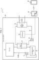
- FIG. 1 is a diagram illustrating a conceptual configuration of a fuel cell device 10 and an example configuration of a power generation system 1 including the fuel cell device 10 according to an embodiment of the present disclosure.
- the fuel cell device 10 can be interconnected to or disconnected from a system.
- the fuel cell device 10 can supply electric power to a load (for example, a common device) via a power conditioner while being interconnected to the system.
- the power conditioner converts electric power generated by the fuel cell device 10 to electric power having properties suitable for output to the system.
- the fuel cell device 10 can supply electric power to auxiliaries and the like included in the fuel cell device 10 while being disconnected from the system.
- the power generation system 1 includes the fuel cell device 10, a first electronic device 30, and a second electronic device 40.
- the first electronic device 30 provides a notification to a user of the power generation system 1 (hereinafter simply referred to as "user") and makes hot water that is heated with exhaust heat of a fuel cell 11 be discharged in response to a user operation.
- the first electronic device 30 need not be of a specific type as long as the first electronic device 30 includes the function as described above, and is a water-heater remote controller in this embodiment.
- the water-heater remote controller is installed inside a house or the like and makes hot water be discharged into a bathtub or the like in response to a user operation.
- the first electronic device 30 may be a computer that manages the discharge, temperature, and the like of hot water in a factory or the like.
- the user may be the administrator of the power generation system 1.
- the configuration of the first electronic device 30 will be described in detail below.
- the second electronic device 40 can communicate with the first electronic device 30.
- the second electronic device 40 need not be of a specific type as long as the second electronic device 40 includes the function as described above, and is a mobile communication terminal in this embodiment.
- the mobile communication terminal is a mobile terminal carried by the user and is, for example, a smartphone, a smartwatch, a tablet terminal, a game machine, or an e-book reader.
- the second electronic device 40 may be a car navigation system that can communicate with the first electronic device 30. The configuration of the second electronic device 40 will be described in detail below.
- the fuel cell device 10 includes the fuel cell 11, a heat exchanger 12, a circulation passage 13, a liquid flow passage 14, and a controller 15.
- the fuel cell device 10 in the example illustrated in FIG. 1 further includes a reformed-water tank 16, a reformed-water pump 17, a heat medium tank 18, and a heat medium pump 19, the fuel cell device 10 need not include some or all of these component elements or may have a different configuration. That is, the fuel cell device 10 need not include all of the component elements illustrated in FIG. 1 .
- the fuel cell device 10 may include a component element other than those illustrated in FIG. 1 .
- the fuel cell device 10 may make hot water that is stored in the heat medium tank 18 be directly discharged through a hot-water supply passage 21 described below.
- the fuel cell 11 generates power by using supplied gas, air, and reformed water. With power generation, the fuel cell 11 releases high-temperature exhaust gas.
- the fuel cell 11 includes an exhaust passage. The fuel cell 11 sends the exhaust gas to the heat exchanger 12 through the exhaust passage.
- the heat exchanger 12 makes exhaust heat released from the fuel cell 11 as the exhaust gas undergo heat exchange with a heat medium.
- the heat medium is a fluid, such as water or antifreeze, of high specific heat.
- Reformed water from the exhaust gas condensed in heat exchange with the heat medium in the heat exchanger 12 is stored in the reformed-water tank 16.
- the reformed-water tank 16 may temporarily store the reformed water.
- the reformed-water tank 16 may be covered by a heat insulator.
- the reformed water stored in the reformed-water tank 16 is pressed by the reformed-water pump 17 to an increased pressure and supplied to the fuel cell 11. Exhaust gas not condensed in the heat exchanger 12 is released from the fuel cell device 10.
- the circulation passage 13 allows the heat medium to circulate therethrough and pass through the heat exchanger 12.
- the circulation passage 13 may allow the heat medium to circulate between the heat exchanger 12 and the heat medium tank 18.
- the heat medium tank 18 may store the heat medium.
- the heat medium tank 18 may be covered by a heat insulator.
- the circulation passage 13 may be provided with the heat medium pump 19.
- the heat medium pump 19 presses the heat medium to an increased pressure to thereby make the heat medium circulate through the circulation passage 13.
- the heat medium pump 19 may operate in response to control by the controller 15.
- the liquid flow passage 14 is a flow passage other than the circulation passage 13 and is related to operations of the fuel cell 11.
- the liquid flow passage 14 includes a supply passage 20 for supplying the reformed water to the fuel cell 11 and the hot-water supply passage 21 for discharging hot water by using heat obtained from the heat medium.
- the supply passage 20 connects the reformed-water tank 16 and the fuel cell 11 with the reformed-water pump 17 therebetween.
- the hot-water supply passage 21 passes through, for example, the inside of the heat medium tank 18. Water supplied to the hot-water supply passage 21 undergoes heat exchange with the heat medium in the heat medium tank 18 and is heated.
- the controller 15 includes one or more processors and a memory.
- the processors may include a general-purpose processor that reads a specific program and executes a specific function and a dedicated processor that is specialized in specific processing.
- the dedicated processor may include an ASIC (application-specific integrated circuit (IC)).
- the processors may include a PLD (programmable logic device).
- a PLD may include an FPGA (field-programmable gate array).
- the controller 15 may be any of an SoC (System-on-a-Chip) and an SiP (System In a Package) that include one or more processors cooperating with each other.
- the controller 15 controls the component elements of the fuel cell device 10 including the fuel cell 11. For example, the controller 15 activates or deactivates the fuel cell 11.
- the controller 15 can communicate with the first electronic device 30 and control the first electronic device 30. For example, the controller 15 obtains necessary data from the first electronic device 30 and outputs to the first electronic device 30 a control signal for performing a necessary operation.
- the controller 15 when the fuel cell 11 is inactive, the controller 15 makes the first electronic device 30 display a notification that the fuel cell 11 is inactive, and when the fuel cell 11 is not reactivated after display of the notification and the user operates the first electronic device 30, the controller 15 makes the first electronic device 30 provide a notification with at least one of a warning sound and warning display.
- the first electronic device 30 is, for example, a water-heater remote controller installed indoors.
- the controller 15 communicates to the user, information indicating that the fuel cell 11 is inactive by using the first electronic device 30. With the warning sound or the like, the user can easily become aware that the fuel cell 11 remains inactive unintentionally even when the user does not become aware of the notification that the fuel cell 11 is inactive, displayed on the first electronic device 30.
- the controller 15 may make the first electronic device 30 transmit information to the second electronic device 40.
- the second electronic device 40 is, for example, a mobile communication terminal such as a smartphone. Therefore, the user can become aware that the fuel cell 11 remains inactive unintentionally even when, for example, the user is out, with a notification from the second electronic device 40 based on the transmitted information.
- the controller 15 may make the first electronic device 30 repeatedly transmit information to the second electronic device 40 until the number of times information is transmitted reaches a predetermined number of times. The user can become aware that the fuel cell 11 remains inactive unintentionally even when the user is, for example, on a trip and stays out for a long period.
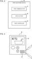
- FIG. 2 is a diagram illustrating an example configuration of the first electronic device 30.
- FIG. 3 is a diagram for explaining a notification to the user of the first electronic device 30.
- the first electronic device 30 may include a first communicator 31, a first notifier 32, and a first controller 33.
- the first communicator 31 is an interface for communicating with the fuel cell device 10 and the second electronic device 40 at least wirelessly or by wire.
- the first communicator 31 can include communication interfaces conforming to mobile communication standards such as 4G (4th Generation) and 5G (5th Generation), a wired LAN (local area network) standard, and a wireless LAN standard.
- the first communicator 31 may, for example, communicate with the fuel cell device 10 by wire and with the second electronic device 40 wirelessly.
- the first notifier 32 provides information to the user.
- the first notifier 32 may include a display that displays an image.
- the display may be a liquid crystal display, an organic EL (electro-luminescence) panel, or the like.
- the display is a touch panel display (touch screen display) including an input function.
- the first notifier 32 also includes a speaker that emits a sound.
- the first notifier 32 may display a notification that the fuel cell 11 is inactive (for example, warning display). In this case, the notification needs to be displayed in a more visually appealing form than a notification about the inactive state displayed for the first time after the fuel cell 11 has become inactive.
- the notification with the warning sound and that with the warning display may be simultaneously provided.
- the first controller 33 controls operations of the first communicator 31 and the first notifier 32 on the basis of a control signal from the controller 15.
- the first controller 33 may manage information (hereinafter referred to as "registration information") about the second electronic device 40 registered by the user as an information transmission destination.
- the first controller 33 may store the registration information in an accessible storage device (for example, a memory or an HDD) and output management information to the controller 15 of the fuel cell device 10.
- the first controller 33 may control the discharge of hot water and may output information to the controller 15 on the basis of user operations. For example, when a user operation is an operation of pressing a button for filling a bathtub with hot water, the first controller 33 may make hot water be discharged and may output to the controller 15 information indicating that the user has operated the first electronic device 30. For example, when a user operation is an operation performed on a set screen of the touch panel display for reactivating the fuel cell 11, the first controller 33 may output to the controller 15 information indicating that the user has performed the operation for reactivating the
- FIG. 4 is a diagram illustrating an example configuration of the second electronic device 40.
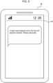
- FIG. 5 is a diagram for explaining a notification to the user of the second electronic device 40.
- the second electronic device 40 may include a second communicator 41, a second notifier 42, and a second controller 43.
- the second communicator 41 is an interface for communicating with the first electronic device 30 at least wirelessly or by wire.
- the second communicator 41 can include communication interfaces conforming to mobile communication standards such as 4G and 5G, a wired LAN standard, and a wireless LAN standard. In this embodiment, the second communicator 41 wirelessly communicates with the first electronic device 30.
- the second notifier 42 provides information to the user.
- the second notifier 42 may include a display that displays an image.
- the display may be a liquid crystal display, an organic EL display, or the like.
- the display may be a touch panel display including an input function.
- the second notifier 42 may include a speaker that emits a sound. As illustrated in FIG. 5 , for example, in response to the elapse of the predetermined period since the start of the inactive state of the fuel cell 11, the second notifier 42 may display a message for encouraging the user to reactivate the fuel cell 11.
- the second notifier 42 may emit a warning sound.
- the second controller 43 controls operations of the second communicator 41 and the second notifier 42 on the basis of information about the inactive state of the fuel cell 11 transmitted from the first electronic device 30.
- the second controller 43 controls the second electronic device 40 as a whole in order to implement functions of a mobile communication terminal including data communication and voice calls.
- FIG. 6 is a flowchart for explaining processes performed by the controller 15 of the fuel cell device 10.
- the controller 15 determines the state of the fuel cell 11, and if the fuel cell 11 is inactive (Yes in step S1), makes the first electronic device 30 display a notification that the fuel cell 11 is inactive (step S2).
- the controller 15 may keep the first electronic device 30 displaying the notification of the inactive state during a period from the start of the inactive state of the fuel cell 11 to reactivation of the fuel cell 11 regardless of whether the user is at home or out. If the fuel cell 11 is active (No in step S1), the controller 15 does not perform a process for providing a notification to the user.
- step S3 the controller 15 checks whether the fuel cell 11 is reactivated. If the fuel cell 11 is reactivated (Yes in step S3), the controller 15 ends the series of processes. If the fuel cell 11 is not reactivated (No in step S3), the controller 15 proceeds to the process in step S4. Determination in step S3 can be performed, for example, within one day after the fuel cell 11 has become inactive.
- step S4 the controller 15 makes the first electronic device 30 provide a notification with at least one of a warning sound and warning display (step S5).
- the controller 15 ends the series of processes.
- step S6 If a user operation is not performed on the first electronic device 30 (No in step S4) or the fuel cell 11 is not reactivated (No in step S6), the controller 15 proceeds to the process in step S7.
- the controller 15 If a predetermined period is not elapsed since the start of the inactive state of the fuel cell 11 (No in step S7), the controller 15 returns to the process in step S4.
- the predetermined period is, for example, one week but is not limited to this.
- step S7 determines whether the predetermined period is elapsed since the start of the inactive state of the fuel cell 11 (Yes in step S7). If the predetermined period is elapsed since the start of the inactive state of the fuel cell 11 (Yes in step S7), the controller 15 determines whether the second electronic device 40 is registered (step S8). If the second electronic device 40 is not registered (No in step S8), the controller 15 ends the series of processes.
- the controller 15 makes the first electronic device 30 transmit information to the second electronic device 40 (step S9).
- the second electronic device 40 displays, for example, a message for encouraging the user to reactivate the fuel cell 11 (see FIG. 5 ), on the basis of the information transmitted from the first electronic device 30.
- the user may reactivate the fuel cell 11 on the set screen of the first electronic device 30 when the user is at home.
- the user may operate the first electronic device 30 by using the second electronic device 40 to thereby reactivate the fuel cell 11.
- step S10 If the fuel cell 11 is reactivated (Yes in step S10), the controller 15 ends the series of processes. If the fuel cell 11 is not reactivated (No in step S10), the controller 15 determines whether the number of times information is transmitted to the second electronic device 40 reaches a predetermined number of times (step S11).
- the predetermined number of times is, for example, three times but is not limited to this.
- step S11 If the number of times information is transmitted to the second electronic device 40 reaches the predetermined number of times (Yes in step S11), the controller 15 ends the series of processes. If the number of times information is transmitted to the second electronic device 40 does not reach the predetermined number of times (No in step S11), the controller 15 returns to the process in step S9. That is, the controller 15 makes the first electronic device 30 transmit information again to the second electronic device 40.
- the fuel cell device 10 can avoid the inactive state of the fuel cell 11 not intended by the user with the above-described configuration.
- the fuel cell 11 is inactive, the user is unable to satisfactorily enjoy advantages and returns, including CO 2 (carbon dioxide) reduction, reduction of primary energy, and reduction of electricity expenses, from the power generation system 1.
- CO 2 carbon dioxide
- the fuel cell device 10 according to this embodiment can allow the user to avoid such a disadvantage.
- the fuel cell device 10 can notify the user of the inactive state of the fuel cell 11 even when the user does not become aware of a notification provided by the first electronic device 30 or when the user is not in the vicinity of the first electronic device 30, by making the first electronic device 30 transmit information to the second electronic device 40. Therefore, the fuel cell device 10 can encourage the user to reactivate the fuel cell 11 to thereby increase the effect of avoiding the inactive state of the fuel cell 11.
- the controller 15 may make the first electronic device 30 transmit information to the second electronic device 40 not only in response to the elapse of the predetermined period since the start of the inactive state of the fuel cell 11 but also on the basis of a return from reactivation of the fuel cell 11. That is, the controller 15 may calculate a return from reactivation of the fuel cell 11, and when the predetermined period has been elapsed and the controller 15 determines that a return is brought, may make the first electronic device 30 transmit information to the second electronic device 40.
- the return may be calculated on the basis of, for example, the price of electricity presented by the power company, the time when hot water is discharged, and the like. When the calculated return exceeds a threshold, the controller 15 may determine that a return is brought.
- the threshold may be, for example, a fixed value such as 1000 yen or a value that changes depending on the season or the like.
- the controller 15 can include the calculated return in a message provided by the second electronic device 40 to thereby further encourage the user to reactivate the fuel cell 11.
- the controller 15 may make the first electronic device 30 transmit information to the second electronic device 40 on the basis of a return from reactivation of the fuel cell 11.
- the controller 15 may change intervals at which information is transmitted. For example, the controller 15 may make the time interval between the second information transmission and the third information transmission shorter than the time interval between the first information transmission and the second information transmission.
- the controller 15 may change intervals at which information is transmitted to the second electronic device 40 on the basis of, for example, the season. For example, hot water is discharged more frequently in winter than in summer, and therefore, the fuel cell 11 being inactive is more disadvantages to the user. Therefore, for repeated information transmission to the second electronic device 40 in winter, the controller 15 may make retransmission be performed at shorter time intervals than in summer.
Landscapes
- Engineering & Computer Science (AREA)
- Chemical & Material Sciences (AREA)
- General Chemical & Material Sciences (AREA)
- Sustainable Development (AREA)
- Sustainable Energy (AREA)
- Manufacturing & Machinery (AREA)
- Chemical Kinetics & Catalysis (AREA)
- Electrochemistry (AREA)
- Life Sciences & Earth Sciences (AREA)
- Combustion & Propulsion (AREA)
- Physics & Mathematics (AREA)
- Thermal Sciences (AREA)
- Mechanical Engineering (AREA)
- General Engineering & Computer Science (AREA)
- Computer Hardware Design (AREA)
- Computer Networks & Wireless Communication (AREA)
- Fuel Cell (AREA)
- Heat-Pump Type And Storage Water Heaters (AREA)
Applications Claiming Priority (2)
| Application Number | Priority Date | Filing Date | Title |
|---|---|---|---|
| JP2020180664 | 2020-10-28 | ||
| PCT/JP2021/034197 WO2022091626A1 (fr) | 2020-10-28 | 2021-09-16 | Dispositif de pile à combustible |
Publications (2)
| Publication Number | Publication Date |
|---|---|
| EP4239734A1 true EP4239734A1 (fr) | 2023-09-06 |
| EP4239734A4 EP4239734A4 (fr) | 2025-07-09 |
Family
ID=81382349
Family Applications (1)
| Application Number | Title | Priority Date | Filing Date |
|---|---|---|---|
| EP21885745.6A Pending EP4239734A4 (fr) | 2020-10-28 | 2021-09-16 | Dispositif de pile à combustible |
Country Status (5)
| Country | Link |
|---|---|
| US (1) | US20230395831A1 (fr) |
| EP (1) | EP4239734A4 (fr) |
| JP (2) | JP7525634B2 (fr) |
| CN (1) | CN116420253A (fr) |
| WO (1) | WO2022091626A1 (fr) |
Families Citing this family (1)
| Publication number | Priority date | Publication date | Assignee | Title |
|---|---|---|---|---|
| WO2022091626A1 (fr) * | 2020-10-28 | 2022-05-05 | 京セラ株式会社 | Dispositif de pile à combustible |
Family Cites Families (10)
| Publication number | Priority date | Publication date | Assignee | Title |
|---|---|---|---|---|
| JP3916478B2 (ja) * | 2002-02-20 | 2007-05-16 | アイシン精機株式会社 | 燃料電池システム |
| JP2005114344A (ja) * | 2003-09-18 | 2005-04-28 | Matsushita Electric Ind Co Ltd | コージェネレーション装置 |
| JP5151745B2 (ja) * | 2008-07-07 | 2013-02-27 | パナソニック株式会社 | コージェネレーション装置の故障診断方法 |
| JP2011166970A (ja) * | 2010-02-10 | 2011-08-25 | Fujitsu Toshiba Mobile Communications Ltd | 電子機器 |
| US9879879B2 (en) * | 2011-11-09 | 2018-01-30 | Panasonic Intellectual Property Management Co., Ltd. | Cogeneration system and method for controlling same |
| JP6023978B2 (ja) | 2012-08-30 | 2016-11-09 | パナソニックIpマネジメント株式会社 | 発電システム |
| JP6101925B2 (ja) * | 2012-10-02 | 2017-03-29 | パナソニックIpマネジメント株式会社 | 燃料電池システム |
| JP2019186109A (ja) * | 2018-04-13 | 2019-10-24 | アイシン精機株式会社 | 燃料電池システム |
| JP6502562B1 (ja) * | 2018-08-06 | 2019-04-17 | 東京瓦斯株式会社 | 発電システム |
| WO2022091626A1 (fr) * | 2020-10-28 | 2022-05-05 | 京セラ株式会社 | Dispositif de pile à combustible |
-
2021
- 2021-09-16 WO PCT/JP2021/034197 patent/WO2022091626A1/fr not_active Ceased
- 2021-09-16 CN CN202180072484.9A patent/CN116420253A/zh active Pending
- 2021-09-16 US US18/250,751 patent/US20230395831A1/en active Pending
- 2021-09-16 EP EP21885745.6A patent/EP4239734A4/fr active Pending
- 2021-09-16 JP JP2022558911A patent/JP7525634B2/ja active Active
-
2024
- 2024-07-18 JP JP2024115095A patent/JP2024133311A/ja active Pending
Also Published As
| Publication number | Publication date |
|---|---|
| US20230395831A1 (en) | 2023-12-07 |
| JP7525634B2 (ja) | 2024-07-30 |
| CN116420253A (zh) | 2023-07-11 |
| JP2024133311A (ja) | 2024-10-01 |
| EP4239734A4 (fr) | 2025-07-09 |
| JPWO2022091626A1 (fr) | 2022-05-05 |
| WO2022091626A1 (fr) | 2022-05-05 |
Similar Documents
| Publication | Publication Date | Title |
|---|---|---|
| US9124100B2 (en) | Power supply system, control device of power supply system, operation method of power supply system, and control method of power supply system | |
| JP6013076B2 (ja) | エネルギー管理装置、エネルギー管理システムおよびエネルギー管理方法 | |
| CN102414951A (zh) | 供需控制装置、供需控制方法及程序 | |
| JP2013229995A (ja) | 電力管理装置、表示装置、表示方法、および画像作成プログラム | |
| EP4239734A1 (fr) | Dispositif de pile à combustible | |
| WO2014024463A1 (fr) | Dispositif de gestion d'énergie et procédé de gestion d'énergie | |
| JP2017191523A (ja) | 表示制御方法、表示制御プログラム、及び表示制御システム | |
| JPWO2016084391A1 (ja) | 電力制御装置、電力制御方法、および電力制御プログラム | |
| JP5908258B2 (ja) | 電力管理装置、電力管理装置の制御方法および電力管理装置の制御プログラム | |
| KR20180036972A (ko) | 미래 에너지 레벨 결정들에 기반한 부하 및 에너지원의 제어 | |
| JP2015022426A (ja) | 宅内コントローラ、宅内機器管理システム、通知メッセージ表示方法及びプログラム | |
| JP2007228696A (ja) | 省エネルギ支援システム | |
| CN106850358A (zh) | 智能电器及其控制方法、装置、系统 | |
| JP2006017645A (ja) | 電力使用状況表示装置,電力使用状況表示方法およびインターフォン | |
| JP7159240B2 (ja) | 余剰電力活用システム | |
| JP5875556B2 (ja) | エネルギー管理システム、表示装置、表示方法及びプログラム | |
| JP2013224765A (ja) | 熱供給装置 | |
| CN113258961A (zh) | 一种无线充电方法、接收器及发射器 | |
| JP2004011973A (ja) | ネットワーク対応給湯器及び給湯器の遠隔操作システム | |
| CN106549405A (zh) | 可检测电量的电力控制系统 | |
| JP4957341B2 (ja) | 給湯装置 | |
| JP6615027B2 (ja) | 燃料電池発電システム | |
| JP6390413B2 (ja) | 電力管理システム | |
| JP2017118786A (ja) | 電力供給システム | |
| CN114013279A (zh) | 动力电池放电设备及放电控制方法 |
Legal Events
| Date | Code | Title | Description |
|---|---|---|---|
| STAA | Information on the status of an ep patent application or granted ep patent |
Free format text: STATUS: THE INTERNATIONAL PUBLICATION HAS BEEN MADE |
|
| PUAI | Public reference made under article 153(3) epc to a published international application that has entered the european phase |
Free format text: ORIGINAL CODE: 0009012 |
|
| STAA | Information on the status of an ep patent application or granted ep patent |
Free format text: STATUS: REQUEST FOR EXAMINATION WAS MADE |
|
| 17P | Request for examination filed |
Effective date: 20230427 |
|
| AK | Designated contracting states |
Kind code of ref document: A1 Designated state(s): AL AT BE BG CH CY CZ DE DK EE ES FI FR GB GR HR HU IE IS IT LI LT LU LV MC MK MT NL NO PL PT RO RS SE SI SK SM TR |
|
| DAV | Request for validation of the european patent (deleted) | ||
| DAX | Request for extension of the european patent (deleted) | ||
| A4 | Supplementary search report drawn up and despatched |
Effective date: 20250610 |
|
| RIC1 | Information provided on ipc code assigned before grant |
Ipc: H01M 8/04228 20160101ALI20250603BHEP Ipc: H01M 8/04029 20160101ALI20250603BHEP Ipc: F24H 15/464 20220101ALI20250603BHEP Ipc: F24H 15/457 20220101ALI20250603BHEP Ipc: F24H 15/421 20220101ALI20250603BHEP Ipc: F24H 15/277 20220101ALI20250603BHEP Ipc: F24H 15/16 20220101ALI20250603BHEP Ipc: F24D 19/10 20060101ALI20250603BHEP Ipc: F24D 17/00 20220101ALI20250603BHEP Ipc: F24H 1/00 20220101ALI20250603BHEP Ipc: F24H 15/395 20220101ALI20250603BHEP Ipc: H01M 8/04694 20160101ALI20250603BHEP Ipc: H01M 8/04313 20160101ALI20250603BHEP Ipc: H01M 8/043 20160101ALI20250603BHEP Ipc: H01M 8/04 20160101ALI20250603BHEP Ipc: H01M 8/00 20160101AFI20250603BHEP |
|
| STAA | Information on the status of an ep patent application or granted ep patent |
Free format text: STATUS: THE APPLICATION IS DEEMED TO BE WITHDRAWN |