EP4239767A1 - Système de batterie - Google Patents
Système de batterie Download PDFInfo
- Publication number
- EP4239767A1 EP4239767A1 EP22159701.6A EP22159701A EP4239767A1 EP 4239767 A1 EP4239767 A1 EP 4239767A1 EP 22159701 A EP22159701 A EP 22159701A EP 4239767 A1 EP4239767 A1 EP 4239767A1
- Authority
- EP
- European Patent Office
- Prior art keywords
- cooling
- media
- cold plate
- loop
- flow
- Prior art date
- Legal status (The legal status is an assumption and is not a legal conclusion. Google has not performed a legal analysis and makes no representation as to the accuracy of the status listed.)
- Granted
Links
Images



Classifications
-
- H—ELECTRICITY
- H01—ELECTRIC ELEMENTS
- H01M—PROCESSES OR MEANS, e.g. BATTERIES, FOR THE DIRECT CONVERSION OF CHEMICAL ENERGY INTO ELECTRICAL ENERGY
- H01M10/00—Secondary cells; Manufacture thereof
- H01M10/60—Heating or cooling; Temperature control
- H01M10/65—Means for temperature control structurally associated with the cells
- H01M10/655—Solid structures for heat exchange or heat conduction
- H01M10/6554—Rods or plates
-
- H—ELECTRICITY
- H01—ELECTRIC ELEMENTS
- H01M—PROCESSES OR MEANS, e.g. BATTERIES, FOR THE DIRECT CONVERSION OF CHEMICAL ENERGY INTO ELECTRICAL ENERGY
- H01M10/00—Secondary cells; Manufacture thereof
- H01M10/60—Heating or cooling; Temperature control
- H01M10/61—Types of temperature control
- H01M10/613—Cooling or keeping cold
-
- H—ELECTRICITY
- H01—ELECTRIC ELEMENTS
- H01M—PROCESSES OR MEANS, e.g. BATTERIES, FOR THE DIRECT CONVERSION OF CHEMICAL ENERGY INTO ELECTRICAL ENERGY
- H01M10/00—Secondary cells; Manufacture thereof
- H01M10/60—Heating or cooling; Temperature control
- H01M10/62—Heating or cooling; Temperature control specially adapted for specific applications
- H01M10/625—Vehicles
-
- H—ELECTRICITY
- H01—ELECTRIC ELEMENTS
- H01M—PROCESSES OR MEANS, e.g. BATTERIES, FOR THE DIRECT CONVERSION OF CHEMICAL ENERGY INTO ELECTRICAL ENERGY
- H01M10/00—Secondary cells; Manufacture thereof
- H01M10/60—Heating or cooling; Temperature control
- H01M10/64—Heating or cooling; Temperature control characterised by the shape of the cells
- H01M10/647—Prismatic or flat cells, e.g. pouch cells
-
- H—ELECTRICITY
- H01—ELECTRIC ELEMENTS
- H01M—PROCESSES OR MEANS, e.g. BATTERIES, FOR THE DIRECT CONVERSION OF CHEMICAL ENERGY INTO ELECTRICAL ENERGY
- H01M10/00—Secondary cells; Manufacture thereof
- H01M10/60—Heating or cooling; Temperature control
- H01M10/65—Means for temperature control structurally associated with the cells
- H01M10/655—Solid structures for heat exchange or heat conduction
- H01M10/6556—Solid parts with flow channel passages or pipes for heat exchange
-
- H—ELECTRICITY
- H01—ELECTRIC ELEMENTS
- H01M—PROCESSES OR MEANS, e.g. BATTERIES, FOR THE DIRECT CONVERSION OF CHEMICAL ENERGY INTO ELECTRICAL ENERGY
- H01M10/00—Secondary cells; Manufacture thereof
- H01M10/60—Heating or cooling; Temperature control
- H01M10/65—Means for temperature control structurally associated with the cells
- H01M10/656—Means for temperature control structurally associated with the cells characterised by the type of heat-exchange fluid
- H01M10/6567—Liquids
- H01M10/6568—Liquids characterised by flow circuits, e.g. loops, located externally to the cells or cell casings
-
- H—ELECTRICITY
- H01—ELECTRIC ELEMENTS
- H01M—PROCESSES OR MEANS, e.g. BATTERIES, FOR THE DIRECT CONVERSION OF CHEMICAL ENERGY INTO ELECTRICAL ENERGY
- H01M50/00—Constructional details or processes of manufacture of the non-active parts of electrochemical cells other than fuel cells, e.g. hybrid cells
- H01M50/20—Mountings; Secondary casings or frames; Racks, modules or packs; Suspension devices; Shock absorbers; Transport or carrying devices; Holders
- H01M50/204—Racks, modules or packs for multiple batteries or multiple cells
- H01M50/207—Racks, modules or packs for multiple batteries or multiple cells characterised by their shape
- H01M50/209—Racks, modules or packs for multiple batteries or multiple cells characterised by their shape adapted for prismatic or rectangular cells
-
- H—ELECTRICITY
- H01—ELECTRIC ELEMENTS
- H01M—PROCESSES OR MEANS, e.g. BATTERIES, FOR THE DIRECT CONVERSION OF CHEMICAL ENERGY INTO ELECTRICAL ENERGY
- H01M50/00—Constructional details or processes of manufacture of the non-active parts of electrochemical cells other than fuel cells, e.g. hybrid cells
- H01M50/20—Mountings; Secondary casings or frames; Racks, modules or packs; Suspension devices; Shock absorbers; Transport or carrying devices; Holders
- H01M50/249—Mountings; Secondary casings or frames; Racks, modules or packs; Suspension devices; Shock absorbers; Transport or carrying devices; Holders specially adapted for aircraft or vehicles, e.g. cars or trains
-
- H—ELECTRICITY
- H01—ELECTRIC ELEMENTS
- H01M—PROCESSES OR MEANS, e.g. BATTERIES, FOR THE DIRECT CONVERSION OF CHEMICAL ENERGY INTO ELECTRICAL ENERGY
- H01M2220/00—Batteries for particular applications
- H01M2220/20—Batteries in motive systems, e.g. vehicle, ship, plane
-
- Y—GENERAL TAGGING OF NEW TECHNOLOGICAL DEVELOPMENTS; GENERAL TAGGING OF CROSS-SECTIONAL TECHNOLOGIES SPANNING OVER SEVERAL SECTIONS OF THE IPC; TECHNICAL SUBJECTS COVERED BY FORMER USPC CROSS-REFERENCE ART COLLECTIONS [XRACs] AND DIGESTS
- Y02—TECHNOLOGIES OR APPLICATIONS FOR MITIGATION OR ADAPTATION AGAINST CLIMATE CHANGE
- Y02E—REDUCTION OF GREENHOUSE GAS [GHG] EMISSIONS, RELATED TO ENERGY GENERATION, TRANSMISSION OR DISTRIBUTION
- Y02E60/00—Enabling technologies; Technologies with a potential or indirect contribution to GHG emissions mitigation
- Y02E60/10—Energy storage using batteries
Definitions
- the present disclosure relates to the field of battery modules, and more particular to battery modules with a cold plate configured to be used in energy storage systems.
- Battery modules for energy storage solutions may comprise a plurality of prismatic battery cells which are stacked within a casing of the battery module.
- Battery cells generate heat when charged/discharged which needs to be controlled in order for the battery cells to operate within predetermined operating conditions for optimal functionality.
- Cooling can be provided by placing a cooling arrangement, such as a cold plate, outside the casing of the battery module, which is not an optimal solution due to limited thermal conductivity of the material in the casing of the battery module.
- the cooling arrangements may be integrated within the battery casing, i.e. between a surface of the battery cells and the module casing, which may lead to a more complex product manufacturing process.
- the volume of the battery module with the cooling arrangement irrespectively if the cooling arrangement is arranged outside the battery module or integrating within the battery module, is increased.
- An object of the present disclosure is to provide an improved design of a system comprising a plurality of battery modules and a cold plate for cooling the battery modules which seeks to mitigate or eliminate one or more of the above-identified deficiencies in the art singly or in any combination.
- a system comprising a plurality of battery modules and a cold plate for cooling the plurality of battery modules.
- Each battery module comprises a plurality of battery cells and two side plates, and each side plate has a protruding lower edge wherein the battery cells are stacked with a bottom surface supported by the protruding lower edge of the two side plates.
- the cold plate comprises: a base plate provided with cooling channels, wherein the base plate is thermally connected to the bottom surface of the battery cells in each battery module; an inlet port for feeding cooling media via the cooling channels to an outlet port, and at least one cut-out configured to house the protruding lower edge of the side plates.
- a cold plate for cooling a plurality of battery modules in a system, wherein each battery module comprises a plurality of battery cells and two side plates, each side plate having a protruding lower edge, wherein the battery cells are stacked with a bottom surface supported by the protruding lower edge of the two side plates, wherein the cold plate comprises: a base plate provided with cooling channels, wherein the base plate is configured to be thermally connected to the bottom surface of the battery cells in each battery module; an inlet port for feeding cooling media via the cooling channels to an outlet port, and at least one cut-out configured to house one of the protruding lower edges of the side plates.
- an energy storage system comprising at least one system as disclosed above.
- An advantage with the present invention is that a more efficient cooling of a battery module is achieved since the surface of the cooling channels of the cold plate may be positioned close to the battery cells within the battery module without having to integrate the cooling arrangement in the battery modules.
- the shape of the side plates protects and supports the cells.
- the resulting improved mechanical stability facilitates handling and assembly of the module. This design makes it possible to use one large cold plate to cool several modules, which further simplifies manufacturing, reduces costs and improves reliability due to a reduced number of parts.
- Another advantage is that more volume-efficient design of the system is achieved compared to prior art solutions, since a part of each battery module is housed in a cut-out of the cold plate.
- Each battery module comprises battery cells, which may be prismatic cells (in particular lithium-ion secondary battery cells) and the example embodiments of the system may be used in an energy storage system, ESS, or in an automotive application.
- battery cells which may be prismatic cells (in particular lithium-ion secondary battery cells) and the example embodiments of the system may be used in an energy storage system, ESS, or in an automotive application.
- FIG 1 is a perspective view of a first example of a battery module 10 which in this example comprises five battery cells 11 with a bottom surface 15 and a top side 16.
- the module also comprises two side plates 12.
- Each side plate 12 is in this example L-shaped and together they are configured to position the battery cells 11 adjacent to each other and maintain the form of the battery module 10, e.g. using an adhesive.
- Each side plate 12 comprises a side portion 13 and a protruding lower edge 14, wherein the battery cells are stacked with the bottom surface 15 supported by the protruding lower edge 14 and the side portion 13 extends in a direction perpendicular to the bottom surface 15 of the battery cells.
- the top side 16 may also comprise terminals 17 and exhaust valves (not shown).
- a battery module may comprise additional components, which are not shown in Figure 1 in order to not obscure the inventive concept.
- cell spacers may be placed between each pair of battery cells to provide electrical insulation and improve the compression uniformity along the length of the battery stack.
- end plates may be provided at each end of the battery stack, combining with the side plates to form a complete enclosure for the cells.
- the cell terminals are typically attached to bus bars, e.g. via welding, in order to provide an electrical connection with the cells to enable charging and discharging.
- a cell sensing assembly may be provided on top of the cell stack with temperature and/or voltage sensors which are attached to the cells or bus bars e.g. using a wire harness.
- a top lid may additionally be provided over the cell sensing assembly to protect and insulate the enclosure.
- This design reduces the amount of material needed to maintain the battery cells in a stacked configuration within the battery module. Furthermore, the weight of the battery module is also reduced as well as exposing a large portion of the bottom surface of the battery cells, which may be used to cool the battery cells in an efficient way.
- FIG 2 is an illustrative top view of a first example embodiment of a cold plate 20 for four battery modules 10 (indicated by dotted lines in Figure 2 ), where each battery cell of the battery module has an exposed bottom surface 15 intended to be cooled by the cold plate.
- the cold plate 20 comprises a base plate 21 provided with cooling channels which are schematically illustrated with arrows 28 and 29 in two cooling loops.
- the cold plate 20 comprises an inlet port 24 configured to provide cooling media to a first cooling loop 28 and to a second cooling loop 29 via an inlet manifold 25.
- the cold plate 20 comprises an outlet port 26 configured to receive cooling media from the first cooling loop 28 and the second cooling loop 29 via an outlet manifold 27.
- the cold plate further comprises two cut-outs 22 and 23 configured to house the protruding lower edge 14 of each battery module 10 in order for the bottom surface 15 of the battery cells 11 to be arranged close to the cooling loops 28, 29 of the cold plate 20.
- the respective cut-out 22 and 23 is in this example illustrated with a closed perimeter.
- FIG 3a is an illustrative top view of a second example embodiment of a cold plate 30 for two battery modules 10 (indicated by dotted lines in Figure 3 ), where each battery cell within the battery module has a bottom surface 15 intended to be cooled by the cold plate 30.
- the cold plate 30 comprises a base plate 31 provided with cooling channels which are schematically illustrates with arrows 38 and 39 in two cooling loops.
- the cold plate 30 comprises an inlet port 24 configured to provide cooling media to a first cooling loop 38 and to a second cooling loop 39 via an inlet manifold 25.
- the cold plate 30 comprises an outlet port 26 configured to receive cooling media from the first cooling loop 38 and the second cooling loop 39 via an outlet manifold 27.
- the cold plate further comprises one cut-out 32 configured to house the protruding lower edge 14 of each battery module 10 in order for the bottom surface 15 of the battery cells 11 to be arranged close to the cooling loops 38, 39 of the cold plate 30.
- the cut-out 32 is in this example illustrated with a closed perimeter.
- Figure 3b is a cross-sectional view along A-A of the cold plate of Figure 3a with a cross-sectional view of two battery modules 10 of Figure 1 .
- the bottom surfaces 15 of the battery cells 11 of each battery module 10 are positioned adjacent to the cooling loops in the base plate 31 since one of the protruding lower edges 14 of each battery module 10 is positioned in the cut-out 32.
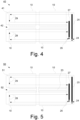
- FIG 4 is an illustrative top view of a third example embodiment of a cold plate 40 for four battery modules 10 (indicated by dotted lines in Figure 4 ), each battery cell of the battery module has an exposed bottom surface intended to be cooled by the cold plate 40.
- the cold plate 40 comprises a base plate 41 provided with cooling channels which are schematically illustrates with arrows 28 and 29 in two cooling loops.
- the cold plate 40 comprises an inlet port 24 configured to provide cooling media to a first cooling loop 28 and to a second cooling loop 29 via an inlet manifold 25.
- the cold plate 40 comprises an outlet port 26 configured to receive cooling media from the first cooling loop 28 and the second cooling loop 29 via an outlet manifold 27.
- the cold plate further comprises one cut-out 42 configured to house one of the protruding lower edges 14 of each battery module 10 in order for the bottom surfaces 15of the battery cells 11 to be arranged close to the cooling loops 28, 29 of the cold plate 40.
- the cut-out 42 is in this example illustrated with an open perimeter.
- FIG 5 is an illustrative top view of a fourth example embodiment of a cold plate 50 for four battery modules 10 (indicated by dotted lines in Figure 4 ), each battery cell of the battery module has an exposed bottom surface intended to be cooled by the cold plate 50.
- the cold plate 50 comprises a base plate 51 provided with cooling channels which are schematically illustrates with arrows 28 and 29 in two cooling loops.
- the cold plate 50 comprises an inlet port 24 configured to provide cooling media to a first cooling loop 28 and to a second cooling loop 29 via an inlet manifold 25.
- the cold plate 50 comprises an outlet port 26 configured to receive cooling media from the first cooling loop 28 and the second cooling loop 29 via an outlet manifold 27.
- the cold plate further comprises two cut-outs 23 and 52 configured to house one of the protruding lower edges 14 of each battery module 10 in order for the bottom surface 15of the battery cells 11 to be arranged close to the cooling loops 28, 29 of the cold plate 50.
- a first cut-out 23 is in this example illustrated with a closed perimeter
- a second cut-out 42 is in this example illustrated with an open perimeter.
- cooling channels 28, 29; 38, 39 in the above described example embodiments may be configured to regulate the flow of cooling media in each cooling loop. This may be achieved by letting the cooling channels have equal height (to ensure that the cold plate has a uniform thickness) and varying width to regulate the flow of cooling media through the cooling channels.
- each cooling loop is divided into cooling sections connected via transport sections and each cooling section is configured to be positioned adjacent to the surface of the battery cells 11 in the respective battery module 10.
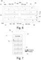
- FIG. 6 is a top view of a cold plate 60, which is an implementation of the first example embodiment of a cold plate described in connection with Figure 2 a cold plate 20, for four battery modules 10 (indicated by dotted lines in Figure 6 ), each battery cell of the battery module has an exposed bottom surface intended to be cooled by the cold plate 60.
- the cold plate 60 comprises a base plate 61 provided with cooling channels in two cooling loops 68 and 69. Furthermore, the cold plate 60 comprises an inlet port 24 configured to provide cooling media to a first cooling loop 68 and to a second cooling loop 69 via an inlet manifold 25. In addition, the cold plate 60 comprises an outlet port 26 configured to receive cooling media from the first cooling loop 68 and the second cooling loop 69 via an outlet manifold 27.
- the cold plate further comprises two cut-outs 22 and 23 configured to house one of the protruding lower edges 14 of each battery module 10 in order for the bottom surface 15 of the battery cells 11 to be arranged close to the cooling loops 68, 69 of the cold plate 60.
- the respective cut-out 22 and 23 is in this example illustrated with a closed perimeter.
- Each cooling loop 68 and 69 comprises several cooling sections 62a-62d and 63a-63d connected via transport sections 64a-64c, 65a-65c, wherein each cooling section 62a-62d and 63a-63d is configured to be positioned adjacent to the battery module 10.
- the inlet port 24 is in this implementation positioned closer to the first cooling loop 68 compared to the second cooling loop 69, and the flow of cooling media at the cooling section 62a closest to the inlet port 24 is higher than the flow of cooling media in the cooling section 62d closest to the outlet port 26.
- the second cooling loop 69 is connected to the inlet port 24 via a first manifold 25 and connected to the outlet port 26 via a second manifold 27, wherein the flow of cooling media in the cooling section 63a closest to the inlet manifold 25 is the same as the flow of cooling media in the cooling section 63d closest to the outlet manifold 27.
- Each transport section 64a-64c and 65a-65c is configured to balance the flow of media between the first cooling loop 68 and second cooling loop 69. This may be performed by reducing the width of the cooling channel in the transport sections compared to the adjacent cooling sections. For instance, the first cooling loop 68 closest to the inlet port 24 has a restricted portion in a first part of the cooling loop. The purpose is to increase the pressure in the first part to ensure an equal flow in both cooling loops. Without this restriction, the cooling media flow in the first cooling loop 68 would be higher than the cooling media flow in the second cooling loop 69 since the cooling media will take the path of least resistance.
- the transport sections 64a-64c, 65a-65c are implemented as restricted portions in the cooling loops.
- the first cooling loop has three restricted portions, but other designs are possible.
- the ratio of the restricted portions in the transport sections 64a-64b, 65a-65c to the wider portions in the cooling sections 62a-62d, 63a-63d should be in the range 30-50%.
- a first portion could be 30% and a second one could be 50% of the width.
- the flow design with restricted portions (in combination with the cutouts 22, 23) enable the use of one large cold plate 61 for several modules 10 instead of separate cold plates for each module.
- FIG. 7 is a perspective view of an energy storage system, ESS, 70 comprising a cabinet 71 with a controller 72, at least one battery system 75 and an inlet 73 and outlet 74 for cooling media.
- the ESS 70 comprises sixteen battery systems 75.
- Each battery system 75 comprises a plurality of battery modules 10 and a cold plate provided with at least one cut-out configured to house at least one of the protruding lower edges of each battery module 10.
- the battery systems may be stacked and/or arranged on shelves.
- the inlet/outlet of the cooling media is connected to the inlet port 24 and the outlet port 26 of each cold plate via a cabinet manifold (not shown) to provide adequate cooling properties to the battery cells within the battery modules.
- the inlet 73/outlet 74 may be positioned on the same cabinet wall (as illustrated) or on different cabinet walls. Furthermore, the inlet 73/ outlet 74 may be positioned on any cabinet wall, e.g. the rear wall.
- FIG 8a is an perspective view of a second example of parts of a battery module 80 which in this example comprises ten battery cells 81 with a bottom surface 15 and a top side 16.
- the battery module further comprises two side plates 12 and two end plates (82).
- Each side plate 12 is in this example L-shaped and together they are configured to position the battery cells 11 adjacent to each other and maintain the form of the battery module 10, e.g. using an adhesive.
- Each side plate 12 comprises a side portion 13 and a protruding lower edge 14, wherein the battery cells are stacked with the bottom surface 15 supported by the protruding lower edge 14 and the side portion 13 extends in a direction perpendicular to the bottom surface 15 of the battery cells.
- Each end plate 82 extends in a direction perpendicular to the bottom surface 15 and the side portion 13 of the side plates 12, wherein each end plate 82 covers opposing sides of the battery module (80).
- the top side 16 may also comprise terminals and exhaust valves (not shown).
- This design has the same advantages as the first example embodiment of the battery module described in connection with Figure 1 , and also increases the structural stability compared to the first example of the battery module 10 in Figure 1 without increasing the volume of the complete system when placed on a cold plate as illustrated in figure 8b .
- Figure 8b is a side view of a system 85 where two battery modules 80 are placed on the cold plate of Figure 4 .
- the bottom surface 15 of the battery cells 81 of each battery module 80 is positioned adjacent to the cooling loops in the base plate 41 since one of the protruding lower edges 14 of each battery module 80 is positioned in the cut-out 42.
- This disclosure relates to a system comprising: a plurality of battery modules, wherein each battery module comprises a plurality of battery cells and two side plates, each side plate having a protruding lower edge, wherein the battery cells are stacked with a bottom surface supported by the protruding lower edge of the two side plates; and a cold plate for cooling the plurality of battery modules; wherein the cold plate comprises: a base plate provided with cooling channels, wherein the base plate is thermally connected to the bottom surface of the battery cells in each battery module; an inlet port for feeding cooling media via the cooling channels to an outlet port, and at least one cut-out configured to house one of the protruding lower edges of the side plates.
- each of the two side plates further comprises a side portion extending in a direction perpendicular to the bottom surface of the battery cells, wherein each side plate further covers opposing sides of the battery module.
- each battery module further comprises two end plates extending in a direction perpendicular to the bottom surface and the side portion of the side plates, wherein each end plate covers opposing sides of the battery module.
- each side plate has an L-shape.
- Other shapes e.g. a bracket shape, with a protruding lower edge may be used that supports the bottom surface of the battery cells in a battery module.
- the at least one cut-out comprises a cut-out with a closed perimeter.
- the at least one cut-out comprises a cut-out with an open perimeter.
- the cooling channels have equal height and varying width to regulate the flow of cooling media through the cooling channels.
- terminal connections are provided on a top surface opposite to the bottom surface.
- the cooling channels comprises a first cooling loop.
- the cooling channels comprises an inlet manifold and an outlet manifold to provide cooling media from the inlet port to the outlet port via the first cooling loop and a second cooling loop, wherein the at least one cut-out is arranged between the first cooling loop and the second cooling loop.
- the cooling channels are configured to regulate the flow of cooling media in each cooling loop.
- the cooling channels have equal height and varying width to regulate the flow of cooling media in each cooling loop.
- each cooling loop comprises several cooling sections connected via transport sections, wherein each cooling section is positioned adjacent to the battery module, wherein the inlet port is positioned closer to the first cooling loop compared to the second cooling loop, and the flow of cooling media at the cooling section closest to the inlet port is higher than the flow of cooling media in the cooling section closest to the outlet port.
- the second cooling loop is connected to the inlet port via the inlet manifold and connected to the outlet port via the outlet manifold, wherein the flow of cooling media in the cooling section closest to the first manifold is the same as the flow of cooling media in the cooling section closest to the second manifold.
- each transport section is configured to balance the flow of media between the first cooling loop and second cooling loop.
- each battery module comprises a plurality of battery cells and two side plates, each side plate having a protruding lower edge, wherein the battery cells are stacked with a bottom surface supported by the protruding lower edge of the two side plates, wherein the cold plate comprises:
- the at least one cut-out comprises a cut-out with a closed perimeter.
- the at least one cut-out comprises a cut-out with an open perimeter.
- the cooling channels have equal height and varying width to regulate the flow of cooling media through the cooling channels.
- the cooling channels comprises a first cooling loop.
- the cooling channels comprises an inlet manifold and an outlet manifold to provide cooling media from the inlet port to the outlet port via the first cooling loop and a second cooling loop, wherein the at least one cut-out is arranged between the first cooling loop and the second cooling loop.
- the cooling channels are configured to regulate the flow of cooling media in each cooling loop.
- the cooling channels have equal height and varying width to regulate the flow of cooling media in each cooling loop.
- each cooling loop comprises several cooling sections connected via transport sections, wherein each cooling section is configured to be positioned adjacent to the battery module, wherein the inlet port is positioned closer to the first cooling loop compared to the second cooling loop, and the flow of cooling media at the cooling section closest to the inlet port is higher than the flow of cooling media in the cooling section closest to the outlet port.
- the second cooling loop is connected to the inlet port via the inlet manifold and connected to the outlet port via the outlet manifold, wherein the flow of cooling media in the cooling section closest to the first manifold is the same as the flow of cooling media in the cooling section closest to the second manifold.
- each transport section is configured to balance the flow of media between the first cooling loop and second cooling loop.
- This disclosure further relates to an energy storage system comprising at least one system as disclosed above.
Landscapes
- Chemical & Material Sciences (AREA)
- Chemical Kinetics & Catalysis (AREA)
- Electrochemistry (AREA)
- General Chemical & Material Sciences (AREA)
- Engineering & Computer Science (AREA)
- Manufacturing & Machinery (AREA)
- Aviation & Aerospace Engineering (AREA)
- Secondary Cells (AREA)
- Battery Mounting, Suspending (AREA)
Priority Applications (5)
| Application Number | Priority Date | Filing Date | Title |
|---|---|---|---|
| EP22159701.6A EP4239767B1 (fr) | 2022-03-02 | 2022-03-02 | Système de batterie |
| PL22159701.6T PL4239767T3 (pl) | 2022-03-02 | 2022-03-02 | Układ baterii |
| FIEP22159701.6T FI4239767T3 (fi) | 2022-03-02 | 2022-03-02 | Akkujärjestelmä |
| US18/728,750 US12243995B2 (en) | 2022-03-02 | 2023-03-01 | System |
| PCT/EP2023/055091 WO2023166016A1 (fr) | 2022-03-02 | 2023-03-01 | Système |
Applications Claiming Priority (1)
| Application Number | Priority Date | Filing Date | Title |
|---|---|---|---|
| EP22159701.6A EP4239767B1 (fr) | 2022-03-02 | 2022-03-02 | Système de batterie |
Publications (2)
| Publication Number | Publication Date |
|---|---|
| EP4239767A1 true EP4239767A1 (fr) | 2023-09-06 |
| EP4239767B1 EP4239767B1 (fr) | 2024-05-22 |
Family
ID=80625199
Family Applications (1)
| Application Number | Title | Priority Date | Filing Date |
|---|---|---|---|
| EP22159701.6A Active EP4239767B1 (fr) | 2022-03-02 | 2022-03-02 | Système de batterie |
Country Status (5)
| Country | Link |
|---|---|
| US (1) | US12243995B2 (fr) |
| EP (1) | EP4239767B1 (fr) |
| FI (1) | FI4239767T3 (fr) |
| PL (1) | PL4239767T3 (fr) |
| WO (1) | WO2023166016A1 (fr) |
Families Citing this family (1)
| Publication number | Priority date | Publication date | Assignee | Title |
|---|---|---|---|---|
| US12580264B2 (en) * | 2022-11-18 | 2026-03-17 | Moment Energy Inc. | Battery tray |
Citations (6)
| Publication number | Priority date | Publication date | Assignee | Title |
|---|---|---|---|---|
| DE102008059961A1 (de) * | 2008-12-02 | 2010-06-10 | Daimler Ag | Batterie, umfassend einen Zellverbund aus mehreren parallel und/oder seriell miteinander verschalteten Einzelzellen |
| US20200358127A1 (en) * | 2018-01-25 | 2020-11-12 | Panasonic Corporation | Power supply device, vehicle provided with power supply device, and power storage device |
| US20210273278A1 (en) * | 2018-07-09 | 2021-09-02 | Sanyo Electric Co., Ltd. | Battery system, electric vehicle equipped with battery system, and electricity storage device |
| CN113594604A (zh) * | 2021-07-30 | 2021-11-02 | 中国华电科工集团有限公司 | Ctr储能系统液冷快换电池模组 |
| US20220013827A1 (en) * | 2019-02-12 | 2022-01-13 | Sanyo Electric Co., Ltd. | Battery module |
| CN109075283B (zh) * | 2016-05-03 | 2022-01-18 | 罗伯特·博世有限公司 | 用于储能装置的冷却布置 |
Family Cites Families (1)
| Publication number | Priority date | Publication date | Assignee | Title |
|---|---|---|---|---|
| US8835039B2 (en) * | 2011-10-21 | 2014-09-16 | Avl Powertrain Engineering, Inc. | Battery cooling plate and cooling system |
-
2022
- 2022-03-02 EP EP22159701.6A patent/EP4239767B1/fr active Active
- 2022-03-02 FI FIEP22159701.6T patent/FI4239767T3/fi active
- 2022-03-02 PL PL22159701.6T patent/PL4239767T3/pl unknown
-
2023
- 2023-03-01 WO PCT/EP2023/055091 patent/WO2023166016A1/fr not_active Ceased
- 2023-03-01 US US18/728,750 patent/US12243995B2/en active Active
Patent Citations (6)
| Publication number | Priority date | Publication date | Assignee | Title |
|---|---|---|---|---|
| DE102008059961A1 (de) * | 2008-12-02 | 2010-06-10 | Daimler Ag | Batterie, umfassend einen Zellverbund aus mehreren parallel und/oder seriell miteinander verschalteten Einzelzellen |
| CN109075283B (zh) * | 2016-05-03 | 2022-01-18 | 罗伯特·博世有限公司 | 用于储能装置的冷却布置 |
| US20200358127A1 (en) * | 2018-01-25 | 2020-11-12 | Panasonic Corporation | Power supply device, vehicle provided with power supply device, and power storage device |
| US20210273278A1 (en) * | 2018-07-09 | 2021-09-02 | Sanyo Electric Co., Ltd. | Battery system, electric vehicle equipped with battery system, and electricity storage device |
| US20220013827A1 (en) * | 2019-02-12 | 2022-01-13 | Sanyo Electric Co., Ltd. | Battery module |
| CN113594604A (zh) * | 2021-07-30 | 2021-11-02 | 中国华电科工集团有限公司 | Ctr储能系统液冷快换电池模组 |
Also Published As
| Publication number | Publication date |
|---|---|
| PL4239767T3 (pl) | 2024-12-16 |
| FI4239767T3 (fi) | 2024-07-22 |
| WO2023166016A1 (fr) | 2023-09-07 |
| US20250007034A1 (en) | 2025-01-02 |
| US12243995B2 (en) | 2025-03-04 |
| EP4239767B1 (fr) | 2024-05-22 |
Similar Documents
| Publication | Publication Date | Title |
|---|---|---|
| US9759495B2 (en) | Battery cell assembly having heat exchanger with serpentine flow path | |
| US20240030517A1 (en) | Battery Module Having Improved Cooling Structure | |
| US20240234871A1 (en) | Thermal management of a liquid cooled module | |
| KR100937897B1 (ko) | 신규한 공냉식 구조의 중대형 전지팩 | |
| EP1139483B1 (fr) | Système de bloc-batterie refroidi par un fluide | |
| US11217851B2 (en) | Battery module | |
| US20130052491A1 (en) | Thermal management system for a multi-cell array | |
| US11799151B1 (en) | Vehicle battery cell cooling assembly | |
| WO2001075989A2 (fr) | Groupe de batteries a refroidissement actif ayant une plus longue duree de vie muni | |
| JP7108909B2 (ja) | 拘束部材および電池モジュール | |
| KR20180081996A (ko) | 간접 냉각 방식의 배터리 팩 | |
| US20250096403A1 (en) | Battery module, battery pack, and vehicle | |
| US20260112726A1 (en) | Battery system having a battery module | |
| US12243995B2 (en) | System | |
| EP4358235A1 (fr) | Dispositif de refroidissement pour un système de stockage électrique | |
| JP2012059581A (ja) | 組電池構造 | |
| US20240145817A1 (en) | Energy storage device having cooling device for indirect cooling of module connectors and method for cooling cell groups of an energy storage device | |
| US20220407146A1 (en) | Battery cell retention frame | |
| CN218648075U (zh) | 电池包 | |
| US20250379286A1 (en) | Battery Module | |
| US20240123838A1 (en) | Battery module and electric vehicle | |
| CN216288638U (zh) | 一种用于电池包散热的风冷机构 | |
| CN214753919U (zh) | 隔热组件及电池包 | |
| KR101256057B1 (ko) | 이차 전지 모듈 | |
| CN222530709U (zh) | 一种储能设备用支撑架以及储能设备 |
Legal Events
| Date | Code | Title | Description |
|---|---|---|---|
| STAA | Information on the status of an ep patent application or granted ep patent |
Free format text: STATUS: EXAMINATION IS IN PROGRESS |
|
| PUAI | Public reference made under article 153(3) epc to a published international application that has entered the european phase |
Free format text: ORIGINAL CODE: 0009012 |
|
| 17P | Request for examination filed |
Effective date: 20230214 |
|
| AK | Designated contracting states |
Kind code of ref document: A1 Designated state(s): AL AT BE BG CH CY CZ DE DK EE ES FI FR GB GR HR HU IE IS IT LI LT LU LV MC MK MT NL NO PL PT RO RS SE SI SK SM TR |
|
| GRAP | Despatch of communication of intention to grant a patent |
Free format text: ORIGINAL CODE: EPIDOSNIGR1 |
|
| STAA | Information on the status of an ep patent application or granted ep patent |
Free format text: STATUS: GRANT OF PATENT IS INTENDED |
|
| INTG | Intention to grant announced |
Effective date: 20231120 |
|
| GRAS | Grant fee paid |
Free format text: ORIGINAL CODE: EPIDOSNIGR3 |
|
| GRAA | (expected) grant |
Free format text: ORIGINAL CODE: 0009210 |
|
| STAA | Information on the status of an ep patent application or granted ep patent |
Free format text: STATUS: THE PATENT HAS BEEN GRANTED |
|
| REG | Reference to a national code |
Ref country code: DE Ref legal event code: R081 Ref document number: 602022003533 Country of ref document: DE Owner name: NORTHVOLT SYSTEMS AB, SE Free format text: FORMER OWNER: NORTHVOLT AB, STOCKHOLM, SE Ref country code: DE Ref legal event code: R081 Ref document number: 602022003533 Country of ref document: DE Owner name: NORTHVOLT AB, SE Free format text: FORMER OWNER: NORTHVOLT AB, STOCKHOLM, SE |
|
| AK | Designated contracting states |
Kind code of ref document: B1 Designated state(s): AL AT BE BG CH CY CZ DE DK EE ES FI FR GB GR HR HU IE IS IT LI LT LU LV MC MK MT NL NO PL PT RO RS SE SI SK SM TR |
|
| REG | Reference to a national code |
Ref country code: GB Ref legal event code: FG4D |
|
| REG | Reference to a national code |
Ref country code: CH Ref legal event code: EP |
|
| REG | Reference to a national code |
Ref country code: DE Ref legal event code: R096 Ref document number: 602022003533 Country of ref document: DE |
|
| REG | Reference to a national code |
Ref country code: IE Ref legal event code: FG4D |
|
| REG | Reference to a national code |
Ref country code: FI Ref legal event code: FGE |
|
| REG | Reference to a national code |
Ref country code: SE Ref legal event code: TRGR Ref country code: LT Ref legal event code: MG9D |
|
| REG | Reference to a national code |
Ref country code: NL Ref legal event code: MP Effective date: 20240522 |
|
| PG25 | Lapsed in a contracting state [announced via postgrant information from national office to epo] |
Ref country code: IS Free format text: LAPSE BECAUSE OF FAILURE TO SUBMIT A TRANSLATION OF THE DESCRIPTION OR TO PAY THE FEE WITHIN THE PRESCRIBED TIME-LIMIT Effective date: 20240922 |
|
| PG25 | Lapsed in a contracting state [announced via postgrant information from national office to epo] |
Ref country code: BG Free format text: LAPSE BECAUSE OF FAILURE TO SUBMIT A TRANSLATION OF THE DESCRIPTION OR TO PAY THE FEE WITHIN THE PRESCRIBED TIME-LIMIT Effective date: 20240522 |
|
| PG25 | Lapsed in a contracting state [announced via postgrant information from national office to epo] |
Ref country code: HR Free format text: LAPSE BECAUSE OF FAILURE TO SUBMIT A TRANSLATION OF THE DESCRIPTION OR TO PAY THE FEE WITHIN THE PRESCRIBED TIME-LIMIT Effective date: 20240522 |
|
| PG25 | Lapsed in a contracting state [announced via postgrant information from national office to epo] |
Ref country code: GR Free format text: LAPSE BECAUSE OF FAILURE TO SUBMIT A TRANSLATION OF THE DESCRIPTION OR TO PAY THE FEE WITHIN THE PRESCRIBED TIME-LIMIT Effective date: 20240823 |
|
| PG25 | Lapsed in a contracting state [announced via postgrant information from national office to epo] |
Ref country code: PT Free format text: LAPSE BECAUSE OF FAILURE TO SUBMIT A TRANSLATION OF THE DESCRIPTION OR TO PAY THE FEE WITHIN THE PRESCRIBED TIME-LIMIT Effective date: 20240923 |
|
| REG | Reference to a national code |
Ref country code: AT Ref legal event code: MK05 Ref document number: 1689527 Country of ref document: AT Kind code of ref document: T Effective date: 20240522 |
|
| PG25 | Lapsed in a contracting state [announced via postgrant information from national office to epo] |
Ref country code: NL Free format text: LAPSE BECAUSE OF FAILURE TO SUBMIT A TRANSLATION OF THE DESCRIPTION OR TO PAY THE FEE WITHIN THE PRESCRIBED TIME-LIMIT Effective date: 20240522 |
|
| PG25 | Lapsed in a contracting state [announced via postgrant information from national office to epo] |
Ref country code: ES Free format text: LAPSE BECAUSE OF FAILURE TO SUBMIT A TRANSLATION OF THE DESCRIPTION OR TO PAY THE FEE WITHIN THE PRESCRIBED TIME-LIMIT Effective date: 20240522 |
|
| PG25 | Lapsed in a contracting state [announced via postgrant information from national office to epo] |
Ref country code: AT Free format text: LAPSE BECAUSE OF FAILURE TO SUBMIT A TRANSLATION OF THE DESCRIPTION OR TO PAY THE FEE WITHIN THE PRESCRIBED TIME-LIMIT Effective date: 20240522 |
|
| PG25 | Lapsed in a contracting state [announced via postgrant information from national office to epo] |
Ref country code: LV Free format text: LAPSE BECAUSE OF FAILURE TO SUBMIT A TRANSLATION OF THE DESCRIPTION OR TO PAY THE FEE WITHIN THE PRESCRIBED TIME-LIMIT Effective date: 20240522 |
|
| PG25 | Lapsed in a contracting state [announced via postgrant information from national office to epo] |
Ref country code: PT Free format text: LAPSE BECAUSE OF FAILURE TO SUBMIT A TRANSLATION OF THE DESCRIPTION OR TO PAY THE FEE WITHIN THE PRESCRIBED TIME-LIMIT Effective date: 20240923 Ref country code: NO Free format text: LAPSE BECAUSE OF FAILURE TO SUBMIT A TRANSLATION OF THE DESCRIPTION OR TO PAY THE FEE WITHIN THE PRESCRIBED TIME-LIMIT Effective date: 20240822 Ref country code: NL Free format text: LAPSE BECAUSE OF FAILURE TO SUBMIT A TRANSLATION OF THE DESCRIPTION OR TO PAY THE FEE WITHIN THE PRESCRIBED TIME-LIMIT Effective date: 20240522 Ref country code: LV Free format text: LAPSE BECAUSE OF FAILURE TO SUBMIT A TRANSLATION OF THE DESCRIPTION OR TO PAY THE FEE WITHIN THE PRESCRIBED TIME-LIMIT Effective date: 20240522 Ref country code: IS Free format text: LAPSE BECAUSE OF FAILURE TO SUBMIT A TRANSLATION OF THE DESCRIPTION OR TO PAY THE FEE WITHIN THE PRESCRIBED TIME-LIMIT Effective date: 20240922 Ref country code: HR Free format text: LAPSE BECAUSE OF FAILURE TO SUBMIT A TRANSLATION OF THE DESCRIPTION OR TO PAY THE FEE WITHIN THE PRESCRIBED TIME-LIMIT Effective date: 20240522 Ref country code: GR Free format text: LAPSE BECAUSE OF FAILURE TO SUBMIT A TRANSLATION OF THE DESCRIPTION OR TO PAY THE FEE WITHIN THE PRESCRIBED TIME-LIMIT Effective date: 20240823 Ref country code: ES Free format text: LAPSE BECAUSE OF FAILURE TO SUBMIT A TRANSLATION OF THE DESCRIPTION OR TO PAY THE FEE WITHIN THE PRESCRIBED TIME-LIMIT Effective date: 20240522 Ref country code: BG Free format text: LAPSE BECAUSE OF FAILURE TO SUBMIT A TRANSLATION OF THE DESCRIPTION OR TO PAY THE FEE WITHIN THE PRESCRIBED TIME-LIMIT Effective date: 20240522 Ref country code: AT Free format text: LAPSE BECAUSE OF FAILURE TO SUBMIT A TRANSLATION OF THE DESCRIPTION OR TO PAY THE FEE WITHIN THE PRESCRIBED TIME-LIMIT Effective date: 20240522 Ref country code: RS Free format text: LAPSE BECAUSE OF FAILURE TO SUBMIT A TRANSLATION OF THE DESCRIPTION OR TO PAY THE FEE WITHIN THE PRESCRIBED TIME-LIMIT Effective date: 20240822 |
|
| PG25 | Lapsed in a contracting state [announced via postgrant information from national office to epo] |
Ref country code: DK Free format text: LAPSE BECAUSE OF FAILURE TO SUBMIT A TRANSLATION OF THE DESCRIPTION OR TO PAY THE FEE WITHIN THE PRESCRIBED TIME-LIMIT Effective date: 20240522 |
|
| PG25 | Lapsed in a contracting state [announced via postgrant information from national office to epo] |
Ref country code: EE Free format text: LAPSE BECAUSE OF FAILURE TO SUBMIT A TRANSLATION OF THE DESCRIPTION OR TO PAY THE FEE WITHIN THE PRESCRIBED TIME-LIMIT Effective date: 20240522 |
|
| PG25 | Lapsed in a contracting state [announced via postgrant information from national office to epo] |
Ref country code: CZ Free format text: LAPSE BECAUSE OF FAILURE TO SUBMIT A TRANSLATION OF THE DESCRIPTION OR TO PAY THE FEE WITHIN THE PRESCRIBED TIME-LIMIT Effective date: 20240522 |
|
| PG25 | Lapsed in a contracting state [announced via postgrant information from national office to epo] |
Ref country code: SK Free format text: LAPSE BECAUSE OF FAILURE TO SUBMIT A TRANSLATION OF THE DESCRIPTION OR TO PAY THE FEE WITHIN THE PRESCRIBED TIME-LIMIT Effective date: 20240522 |
|
| PG25 | Lapsed in a contracting state [announced via postgrant information from national office to epo] |
Ref country code: SK Free format text: LAPSE BECAUSE OF FAILURE TO SUBMIT A TRANSLATION OF THE DESCRIPTION OR TO PAY THE FEE WITHIN THE PRESCRIBED TIME-LIMIT Effective date: 20240522 Ref country code: EE Free format text: LAPSE BECAUSE OF FAILURE TO SUBMIT A TRANSLATION OF THE DESCRIPTION OR TO PAY THE FEE WITHIN THE PRESCRIBED TIME-LIMIT Effective date: 20240522 Ref country code: DK Free format text: LAPSE BECAUSE OF FAILURE TO SUBMIT A TRANSLATION OF THE DESCRIPTION OR TO PAY THE FEE WITHIN THE PRESCRIBED TIME-LIMIT Effective date: 20240522 Ref country code: CZ Free format text: LAPSE BECAUSE OF FAILURE TO SUBMIT A TRANSLATION OF THE DESCRIPTION OR TO PAY THE FEE WITHIN THE PRESCRIBED TIME-LIMIT Effective date: 20240522 |
|
| REG | Reference to a national code |
Ref country code: DE Ref legal event code: R097 Ref document number: 602022003533 Country of ref document: DE |
|
| PLBE | No opposition filed within time limit |
Free format text: ORIGINAL CODE: 0009261 |
|
| STAA | Information on the status of an ep patent application or granted ep patent |
Free format text: STATUS: NO OPPOSITION FILED WITHIN TIME LIMIT |
|
| PG25 | Lapsed in a contracting state [announced via postgrant information from national office to epo] |
Ref country code: SI Free format text: LAPSE BECAUSE OF FAILURE TO SUBMIT A TRANSLATION OF THE DESCRIPTION OR TO PAY THE FEE WITHIN THE PRESCRIBED TIME-LIMIT Effective date: 20240522 |
|
| 26N | No opposition filed |
Effective date: 20250225 |
|
| PG25 | Lapsed in a contracting state [announced via postgrant information from national office to epo] |
Ref country code: MC Free format text: LAPSE BECAUSE OF FAILURE TO SUBMIT A TRANSLATION OF THE DESCRIPTION OR TO PAY THE FEE WITHIN THE PRESCRIBED TIME-LIMIT Effective date: 20240522 |
|
| REG | Reference to a national code |
Ref country code: CH Ref legal event code: H13 Free format text: ST27 STATUS EVENT CODE: U-0-0-H10-H13 (AS PROVIDED BY THE NATIONAL OFFICE) Effective date: 20251023 |
|
| PG25 | Lapsed in a contracting state [announced via postgrant information from national office to epo] |
Ref country code: LU Free format text: LAPSE BECAUSE OF NON-PAYMENT OF DUE FEES Effective date: 20250302 |
|
| REG | Reference to a national code |
Ref country code: BE Ref legal event code: MM Effective date: 20250331 |
|
| PG25 | Lapsed in a contracting state [announced via postgrant information from national office to epo] |
Ref country code: FR Free format text: LAPSE BECAUSE OF NON-PAYMENT OF DUE FEES Effective date: 20250331 |
|
| PG25 | Lapsed in a contracting state [announced via postgrant information from national office to epo] |
Ref country code: BE Free format text: LAPSE BECAUSE OF NON-PAYMENT OF DUE FEES Effective date: 20250331 |
|
| PG25 | Lapsed in a contracting state [announced via postgrant information from national office to epo] |
Ref country code: CH Free format text: LAPSE BECAUSE OF NON-PAYMENT OF DUE FEES Effective date: 20250331 |
|
| PG25 | Lapsed in a contracting state [announced via postgrant information from national office to epo] |
Ref country code: IE Free format text: LAPSE BECAUSE OF NON-PAYMENT OF DUE FEES Effective date: 20250302 |
|
| PGFP | Annual fee paid to national office [announced via postgrant information from national office to epo] |
Ref country code: SE Payment date: 20260219 Year of fee payment: 5 |
|
| PGFP | Annual fee paid to national office [announced via postgrant information from national office to epo] |
Ref country code: DE Payment date: 20260219 Year of fee payment: 5 |
|
| PGFP | Annual fee paid to national office [announced via postgrant information from national office to epo] |
Ref country code: FI Payment date: 20260219 Year of fee payment: 5 Ref country code: RO Payment date: 20260302 Year of fee payment: 5 Ref country code: IT Payment date: 20260219 Year of fee payment: 5 |
|
| PGFP | Annual fee paid to national office [announced via postgrant information from national office to epo] |
Ref country code: PL Payment date: 20260225 Year of fee payment: 5 |