EP4239783A1 - Batterieanschlussmodul - Google Patents
Batterieanschlussmodul Download PDFInfo
- Publication number
- EP4239783A1 EP4239783A1 EP23156003.8A EP23156003A EP4239783A1 EP 4239783 A1 EP4239783 A1 EP 4239783A1 EP 23156003 A EP23156003 A EP 23156003A EP 4239783 A1 EP4239783 A1 EP 4239783A1
- Authority
- EP
- European Patent Office
- Prior art keywords
- thermal conduction
- conduction pad
- circuit board
- pad
- temperature sensor
- Prior art date
- Legal status (The legal status is an assumption and is not a legal conclusion. Google has not performed a legal analysis and makes no representation as to the accuracy of the status listed.)
- Granted
Links
Images


Classifications
-
- H—ELECTRICITY
- H01—ELECTRIC ELEMENTS
- H01M—PROCESSES OR MEANS, e.g. BATTERIES, FOR THE DIRECT CONVERSION OF CHEMICAL ENERGY INTO ELECTRICAL ENERGY
- H01M10/00—Secondary cells; Manufacture thereof
- H01M10/42—Methods or arrangements for servicing or maintenance of secondary cells or secondary half-cells
- H01M10/48—Accumulators combined with arrangements for measuring, testing or indicating the condition of cells, e.g. the level or density of the electrolyte
- H01M10/486—Accumulators combined with arrangements for measuring, testing or indicating the condition of cells, e.g. the level or density of the electrolyte for measuring temperature
-
- H—ELECTRICITY
- H01—ELECTRIC ELEMENTS
- H01M—PROCESSES OR MEANS, e.g. BATTERIES, FOR THE DIRECT CONVERSION OF CHEMICAL ENERGY INTO ELECTRICAL ENERGY
- H01M10/00—Secondary cells; Manufacture thereof
- H01M10/42—Methods or arrangements for servicing or maintenance of secondary cells or secondary half-cells
- H01M10/48—Accumulators combined with arrangements for measuring, testing or indicating the condition of cells, e.g. the level or density of the electrolyte
- H01M10/482—Accumulators combined with arrangements for measuring, testing or indicating the condition of cells, e.g. the level or density of the electrolyte for several batteries or cells simultaneously or sequentially
-
- H—ELECTRICITY
- H01—ELECTRIC ELEMENTS
- H01M—PROCESSES OR MEANS, e.g. BATTERIES, FOR THE DIRECT CONVERSION OF CHEMICAL ENERGY INTO ELECTRICAL ENERGY
- H01M50/00—Constructional details or processes of manufacture of the non-active parts of electrochemical cells other than fuel cells, e.g. hybrid cells
- H01M50/20—Mountings; Secondary casings or frames; Racks, modules or packs; Suspension devices; Shock absorbers; Transport or carrying devices; Holders
- H01M50/204—Racks, modules or packs for multiple batteries or multiple cells
-
- H—ELECTRICITY
- H01—ELECTRIC ELEMENTS
- H01M—PROCESSES OR MEANS, e.g. BATTERIES, FOR THE DIRECT CONVERSION OF CHEMICAL ENERGY INTO ELECTRICAL ENERGY
- H01M50/00—Constructional details or processes of manufacture of the non-active parts of electrochemical cells other than fuel cells, e.g. hybrid cells
- H01M50/50—Current conducting connections for cells or batteries
- H01M50/502—Interconnectors for connecting terminals of adjacent batteries; Interconnectors for connecting cells outside a battery casing
- H01M50/507—Interconnectors for connecting terminals of adjacent batteries; Interconnectors for connecting cells outside a battery casing comprising an arrangement of two or more busbars within a container structure, e.g. busbar modules
-
- H—ELECTRICITY
- H01—ELECTRIC ELEMENTS
- H01M—PROCESSES OR MEANS, e.g. BATTERIES, FOR THE DIRECT CONVERSION OF CHEMICAL ENERGY INTO ELECTRICAL ENERGY
- H01M50/00—Constructional details or processes of manufacture of the non-active parts of electrochemical cells other than fuel cells, e.g. hybrid cells
- H01M50/50—Current conducting connections for cells or batteries
- H01M50/502—Interconnectors for connecting terminals of adjacent batteries; Interconnectors for connecting cells outside a battery casing
- H01M50/519—Interconnectors for connecting terminals of adjacent batteries; Interconnectors for connecting cells outside a battery casing comprising printed circuit boards [PCB]
-
- H—ELECTRICITY
- H01—ELECTRIC ELEMENTS
- H01M—PROCESSES OR MEANS, e.g. BATTERIES, FOR THE DIRECT CONVERSION OF CHEMICAL ENERGY INTO ELECTRICAL ENERGY
- H01M50/00—Constructional details or processes of manufacture of the non-active parts of electrochemical cells other than fuel cells, e.g. hybrid cells
- H01M50/50—Current conducting connections for cells or batteries
- H01M50/569—Constructional details of current conducting connections for detecting conditions inside cells or batteries, e.g. details of voltage sensing terminals
-
- H—ELECTRICITY
- H01—ELECTRIC ELEMENTS
- H01M—PROCESSES OR MEANS, e.g. BATTERIES, FOR THE DIRECT CONVERSION OF CHEMICAL ENERGY INTO ELECTRICAL ENERGY
- H01M50/00—Constructional details or processes of manufacture of the non-active parts of electrochemical cells other than fuel cells, e.g. hybrid cells
- H01M50/20—Mountings; Secondary casings or frames; Racks, modules or packs; Suspension devices; Shock absorbers; Transport or carrying devices; Holders
- H01M50/204—Racks, modules or packs for multiple batteries or multiple cells
- H01M50/207—Racks, modules or packs for multiple batteries or multiple cells characterised by their shape
- H01M50/209—Racks, modules or packs for multiple batteries or multiple cells characterised by their shape adapted for prismatic or rectangular cells
-
- Y—GENERAL TAGGING OF NEW TECHNOLOGICAL DEVELOPMENTS; GENERAL TAGGING OF CROSS-SECTIONAL TECHNOLOGIES SPANNING OVER SEVERAL SECTIONS OF THE IPC; TECHNICAL SUBJECTS COVERED BY FORMER USPC CROSS-REFERENCE ART COLLECTIONS [XRACs] AND DIGESTS
- Y02—TECHNOLOGIES OR APPLICATIONS FOR MITIGATION OR ADAPTATION AGAINST CLIMATE CHANGE
- Y02E—REDUCTION OF GREENHOUSE GAS [GHG] EMISSIONS, RELATED TO ENERGY GENERATION, TRANSMISSION OR DISTRIBUTION
- Y02E60/00—Enabling technologies; Technologies with a potential or indirect contribution to GHG emissions mitigation
- Y02E60/10—Energy storage using batteries
Definitions
- the present disclosure relates to the field of battery technology, and particularly relates to a battery connection module.
- Cida patent application publication No. CN111435723A discloses a battery connection module, in which a first end portion of a temperature collecting piece formed with an opening, a temperature sensing member is positioned in the opening, the other end of the temperature collecting piece is connected on a busbar.
- the busbar disclosed by the prior art patent application connects electrodes of batteries, heat generated by the batteries will be directly transferred to the busbar, and the heat on the busbar will be transferred to the temperature sensing member at the first end portion of the temperature collecting piece via the temperature collecting piece, there is only one heat transferring path. If the temperature sensing member is provided between an upper surface of a circuit board and the below batteries and is spaced apart from the batteries by the circuit board and a tray, the heat transferring path is longer, which results in accuracy of temperature information collected by the temperature sensor lower and temperature response time longer, and results in sensitivity of temperature information collection poor.
- One main object of the present disclosure is to provide a battery connection module in which a heat transferring path between a temperature sensor and a surface of a side of a circuit board opposite to temperature sensor is shortened so as to overcome at least one deficiency of the above prior art.
- a battery connection module is provided, the battery connection module is used to connect a plurality of batteries, the battery connection module comprises a tray, a plurality of busbars, a circuit board and a temperature measuring assembly; the plurality of busbars are mounted on the tray and are used to connect the plurality of batteries; the circuit board is connected to the plurality of busbars; the a temperature measuring assembly comprises a first thermal conduction pad and a second thermal conduction pad, a plurality of first thermal conduction through-holes, a temperature sensor and a bridging piece; the first thermal conduction pad and a second thermal conduction pad are respectively provided to an upper surface and a lower surface of the circuit board; the plurality of first thermal conduction through-holes penetrate the first thermal conduction pad, the second thermal conduction pad and the circuit board; the temperature sensor is provided to the upper surface or the lower surface of the circuit board and is adjacent to the first thermal conduction pad or
- the temperature sensor may be provided to the upper surface of the circuit board and/or may be adjacent to the first thermal conduction pad.
- a first end of the bridging piece may be connected to the first thermal conduction pad.
- a second end of the bridging piece may be connected to the corresponding busbar.
- the temperature measuring assembly may further comprise a packaging cover.
- the packaging cover may be provided to the upper surface of the circuit board and/or may be used to at least partially package the first thermal conduction pad, the temperature sensor and/or the first end of the bridging piece.
- the first thermal conduction pad may be provided with a first receiving opening.
- the first end of the bridging piece may be provided with a second receiving opening.
- the first receiving opening may correspond to the second receiving opening in position.
- the temperature sensor may be at least partially positioned in a range of the first receiving opening and in a range of the second receiving opening.
- the temperature sensor may be provided to the lower surface of the circuit board and/or may be adjacent to the second thermal conduction pad.
- a first end of the bridging piece may be connected to the first thermal conduction pad.
- a second end of the bridging piece may be connected to the corresponding busbar.
- the temperature measuring assembly may further comprise a packaging cover
- the packaging cover may be provided to the lower surface of the circuit board and/or may be used to at least partially package the second thermal conduction pad, the temperature sensor and/or the plurality of first thermal conduction through-holes.
- the second thermal conduction pad may be provided with a third receiving opening.
- the temperature sensor may be at least partially positioned in a range of the third receiving opening.
- the circuit board may be provided with an electrical connecting point.
- the temperature sensor may be mounted to the electrical connecting point.
- the temperature measuring assembly may further comprise a second thermal conduction through-hole.
- the second thermal conduction through-hole may penetrate the electrical connecting point and the circuit board.
- the electrical connecting point may be a welding pad.
- the temperature sensor may be mounted to the welding pad by a weld manner.
- the temperature measuring assembly may further comprise a third thermal conduction pad.
- one of the third thermal conduction pad and the welding pad may be provided to the upper surface of the circuit board.
- the other of the third thermal conduction pad and the welding pad may be provided to the lower surface of the circuit board.
- the second thermal conduction through-hole may further penetrate the third thermal conduction pad.
- the tray may be provided with an opening.
- the opening may correspond to the second thermal conduction pad and the temperature sensor in position.
- the battery connection module proposed by the present disclosure includes a tray, a plurality of busbars, a circuit board and a temperature measuring assembly.
- the temperature measuring assembly includes a first thermal conduction pad and a second thermal conduction pad, a plurality of first thermal conduction through-holes, a temperature sensor and a bridging piece.
- the first thermal conduction pad and the second thermal conduction pad are respectively provided to an upper surface and a lower surface of the circuit board.
- the plurality of first thermal conduction through-holes penetrate the first thermal conduction pad, the second thermal conduction pad and the circuit board.
- the temperature sensor is provided to an upper surface or a lower surface of the circuit board, and is adjacent to the first thermal conduction pad or the second thermal conduction pad.
- the present disclosure can allow heat at a surface of a side of the circuit board opposite to temperature sensor to be transferred to the temperature sensor via the first thermal conduction pad, the second thermal conduction pad and the first thermal conduction through-hole, heat transferring path is shortened, accuracy of temperature collection of the temperature sensor is promoted, and temperature response time is shortened, sensitivity of temperature information collection is promoted.
- FIG. 1 representatively illustrates an exploded schematic view of a battery pack proposed by the present disclosure.
- the battery connection module 100 proposed by the present disclosure is described by taking the battery connection module 100 applied to a battery pack for example.
- a person skilled in the art easily understands that, in order to apply relevant design of the present disclosure to other types of energy storing devices, various modifications, additions, substitutions, deletions or other variations may be made to following specific embodiments, but these modifications, additions, substitutions, deletions or other variations are still fallen within a scope of a principle of the battery connection module 100 proposed by the present disclosure.
- the battery connection module 100 proposed by the present disclosure is provided on a plurality of batteries of a battery pack, the battery connection module 100 is used to connect the plurality of batteries 200.
- FIG. 2 representatively illustrates an exploded schematic view of the battery connection module 100
- FIG. 3 representatively illustrates a partially enlarged schematic view when the battery connection module 100 and the plurality of batteries of the battery pack are assembled
- FIG. 4 representatively illustrates an exploded schematic view of FIG. 3
- FIG. 5 representatively illustrates a partially enlarged schematic view of FIG. 3 indicated by a dotted-line frame A
- FIG. 6 representatively illustrates an exploded schematic view of FIG. 5
- FIG. 7 representatively illustrates a partial bottom view of FIG. 3 .
- each main constituent part of the battery connection module 100 proposed by the present disclosure will be described in detail in structure, connecting manner and function relationship.
- the battery connection module 100 proposed by the present disclosure includes a tray 110, a plurality of busbars 120, a circuit board 130 and a temperature measuring assembly.
- the plurality of busbars 120 are mounted on the tray 110, the plurality of busbars 120 are used to connect the plurality of batteries 200.
- Each busbar 120 is connected to a voltage collecting wiring of the circuit board 130 via one bridging piece 145.
- the temperature measuring assembly includes a first thermal conduction pad 141 and a second thermal conduction pad 142, a plurality of first thermal conduction through-holes 143, a temperature sensor 144 and the bridging piece 145.
- the first thermal conduction pad 141 and the second thermal conduction pad 142 are respectively provided to an upper surface S1 and a lower surface S2 of the circuit board 130.
- the first thermal conduction through-hole 143 penetrates the first thermal conduction pad 141, the second thermal conduction pad 142 and the circuit board 130.
- the temperature sensor 144 is provided to the upper surface S1 of the circuit board 130 and is adjacent to the first thermal conduction pad 141.
- the bridging piece 145 connects the busbar 120 and the first thermal conduction pad 141.
- the present disclosure can allow heat at a surface of a side of the circuit board 130 opposite to the temperature sensor 144 to be transferred to the temperature sensor 144 via the second thermal conduction pad 142, the first thermal conduction through-hole 143 and the first thermal conduction pad 141, heat transferring path is shortened, accuracy of temperature collection of the temperature sensor 144 is promoted, and temperature response time is shortened, sensitivity of temperature information collection is promoted.
- a first end 145a of the bridging piece 145 is connected to the first thermal conduction pad 141, a second end 145b of the bridging piece 145 is connected to the corresponding busbar 120.
- the first end 145a of the bridging piece 145 connects the first thermal conduction pad 141 and covers each first thermal conduction through-hole 143.
- the temperature measuring assembly further includes a packaging cover 146.
- the packaging cover 146 is provided to the upper surface S1 of the circuit board 130, is used to package the first thermal conduction pad 141, the temperature sensor 144 and the first end 145a of the bridging piece 145, and can provide a thermal conduction function and a protecting function.
- the packaging cover 146 in a construction that the plurality of the first thermal conduction through-holes 143 are not all covered by the first end 145a of the bridging piece 145, the packaging cover 146 also may cover the other first thermal conduction through-hole 143 which is exposed to the first end 145a of the bridging piece 145.
- the packaging cover 146 when the temperature sensor 144 is provided to the upper surface S1 of the circuit board 130 and the temperature measuring assembly includes the packaging cover 146, the packaging cover 146 also may partially package the first thermal conduction pad 141, in other words, in various possible embodiments which conform to the design concept of the present disclosure, when the temperature sensor 144 is provided to the upper surface S1 of the circuit board 130 and the temperature measuring assembly includes the packaging cover 146, the packaging cover 146 may at least partially package the first thermal conduction pad 141.
- a material of the packaging cover 146 may be a thermal conduction adhesive, an antioxidative protecting adhesive or a combination thereof, for example, silica gel, epoxy resin and the like.
- the first thermal conduction pad 141 is provided with a first receiving opening 1411
- the first end 145a of the bridging piece 145 is provided with a second receiving opening 145 1
- the first receiving opening 1411 and the second receiving opening1451 correspond to each other in position.
- the temperature sensor 144 is partially positioned in a range of the first receiving opening 1411 and in a range of the second receiving opening1451.
- the temperature sensor 144 also may be all positioned in the range of the first receiving opening 1411 and in the range of the second receiving opening1451.
- the temperature sensor 144 when the temperature sensor 144 is provided to the upper surface S1 of the circuit board 130 and the first thermal conduction pad 141 is provided with the first receiving opening 1411, the temperature sensor 144 is at least partially positioned in the range of the first receiving opening 1411 and in the range of the second receiving opening 1451.
- the first receiving opening 1411 is provided to a side edge of the first thermal conduction pad 141.
- the second receiving opening1451 is provided to a side edge of the first end 145a of the bridging piece 145.
- the second receiving opening1451 when the first receiving opening 1411 is provided to a side edge of the first thermal conduction pad 141, the second receiving opening1451 also may be provided to a middle portion of the bridging piece 145, that is, the second receiving opening1451 may be a closed opening structure. Moreover, the first receiving opening 1411 also may be provided to a middle portion of the first thermal conduction pad 141, that is, the first receiving opening 1411 may be a closed opening structure, on this basis, the second receiving opening1451 may be provided to a side edge or a middle portion of the first end 145a of the bridging piece 145, but the present disclosure is not limited thereto. In addition, when the first receiving opening 1411 is a closed opening structure, the temperature sensor 144 is all positioned in the range of the first receiving opening 1411.
- a hole wall of the first thermal conduction through-hole 143 may be plated with a metal plating, a material of the metal plating may be cooper or cooper alloy.
- a material of the first thermal conduction pad 141 may be the same as a material of an electrical conduction trace on the circuit board 130, for example but is not limited to cooper.
- a material of the second thermal conduction pad 142 may be the same as a material of an electrical conduction trace on the circuit board 130, for example but is not limited to cooper.
- FIG. 8 representatively illustrates a partially enlarged schematic view of the battery connection module 100 in another exemplary embodiment
- FIG. 9 representatively illustrates an exploded schematic view of FIG. 8
- FIG. 10 representatively illustrates an exploded schematic view of FIG. 8 viewed from another angle
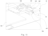
- FIG. 11 representatively illustrates a partial cross sectional view of FIG. 8 .
- the temperature sensor 144 also may be provided to the lower surface S2 of the circuit board 130 and is adjacent to the second thermal conduction pad 142.
- the first end 145a of the bridging piece 145 is connected to the first thermal conduction pad 141
- the second end 145b of the bridging piece 145 is connected to the corresponding busbar 120.
- the temperature sensor 144 may be provided to the upper surface S1 or the lower surface S2 of the circuit board 130, and is adjacent to the first thermal conduction pad 141 or the second thermal conduction pad 142.
- the bridging piece 145 may connect the corresponding busbar 120 and the first thermal conduction pad 141 or the bridging piece 145 may connect the corresponding busbar 120 and the second thermal conduction pad 142.
- the temperature measuring assembly further includes a packaging cover 146.
- the packaging cover 146 is provided to the lower surface S2 of the circuit board 130, is used to partially package the second thermal conduction pad 142, each first thermal conduction through-hole 143 and the temperature sensor 144, and can provide a thermal conduction and a protecting function.
- the packaging cover 146 when the temperature sensor 144 is provided to the lower surface S2 of the circuit board 130 and the temperature measuring assembly includes the packaging cover 146, the packaging cover 146 also may all package the second thermal conduction pad 142 and each first thermal conduction through-hole 143, in other words, in various possible embodiments which conform to the design concept of the present disclosure, when the temperature sensor 144 is provided to the lower surface S2 of the circuit board 130 and the temperature measuring assembly includes the packaging cover 146, the packaging cover 146 may at least partially package the second thermal conduction pad 142 and each first thermal conduction through-hole 143.
- the second thermal conduction pad 142 is provided with a third receiving opening 1421.
- the temperature sensor 144 is all positioned in a range of the third receiving opening 1421.
- the temperature sensor 144 also may be partially positioned in the range of the third receiving opening 1421.
- the temperature sensor 144 is at least partially positioned in the range of the third receiving opening 1421.
- the third receiving opening 1421 is provided to a middle portion of the second thermal conduction pad 142, that is, the third receiving opening 1421 is a closed opening structure, the temperature sensor 144 is all positioned in the range of the third receiving opening 1421.
- the third receiving opening 1421 also may be provided to a side edge of the second thermal conduction pad 142, that is, the third receiving opening 1421 is an opening structure which is opened at a side edge thereof, but the present disclosure is not limited thereto.
- the temperature sensor 144 is at least partially positioned in the range of the third receiving opening 1421.
- the bridging piece 145 is connected to the first thermal conduction pad 141 for example.
- the bridging piece 145 may connect the second thermal conduction pad 142 and the corresponding busbar 120, and so the present disclosure is not limited thereto.
- the first thermal conduction pad 141 can be connected to the voltage collecting wiring on the circuit board 130, besides the bridging piece 145 realizes an electrical connection function between the circuit board 130 and the corresponding batteries 200, the bridging piece 145 can allow heat to be transferred, by the above design, the present disclosure can allow the bridging piece 145 to transfer heat, and can allow heat transferred via the first thermal conduction through-hole 143 which penetrates the circuit board 130 to be more rapidly transferred to the temperature sensor 144.
- the temperature measuring assembly includes a plurality of first thermal conduction through-holes 143.
- the present disclosure can increase thermal conduction amount by the plurality of the first thermal conduction through-holes 143.
- the bridging piece 145 is also penetrated by the first thermal conduction through-hole 143, according to shape difference between the bridging piece 145 and the first thermal conduction pad 141 or the second thermal conduction pad 142, there may be some of the plurality of first thermal conduction through-holes 143 to penetrate the bridging piece 145, the first thermal conduction pad 141, the second thermal conduction pad 142 and the circuit board 130, but the other of the plurality of first thermal conduction through-holes 143 only penetrate the first thermal conduction pad 141, the second thermal conduction pad 142 and the circuit board 130.
- the circuit board 130 is provided with an electrical connecting point
- the temperature sensor 144 is mounted to the electrical connecting point.
- the temperature measuring assembly further includes a second thermal conduction through-hole 147.
- the second thermal conduction through-hole 147 penetrates the electrical connecting point and the circuit board 130.
- the electrical connecting point is two electrical connecting points which each are a welding pad 148, the temperature sensor 144 is mounted to the welding pads 148 by a welding manner, the welding pads 148 are connected to a temperature collecting wiring on the circuit board 130.
- the temperature measuring assembly further includes third thermal conduction pads 149.
- the welding pad 148 is provided to the upper surface S1 of the circuit board 130
- the third thermal conduction pad 149 is provided to the lower surface S2 of the circuit board 130.
- the third thermal conduction pad 149 is provided to the upper surface S1 of the circuit board 130, the welding pad 148 is provided to the lower surface S2 of the circuit board 130. And, the second thermal conduction through-hole 147 further penetrates the welding pad 148 and the third thermal conduction pad 149.
- the temperature measuring assembly further includes the third thermal conduction pad 149
- one of the welding pad 148 and the third thermal conduction pad 149 is provided to the upper surface S1 of the circuit board 130
- the other of the welding pad 148 and the third thermal conduction pad 149 is provided to of the lower surface S2 of the circuit board 130
- the second thermal conduction through-hole 147 further penetrates the welding pad 148 and the third thermal conduction pad 149.
- a hole wall of the second thermal conduction through-hole 147 may be plated with a metal plating, a material of the metal plating may be cooper or cooper alloy.
- a material of the third thermal conduction pad 149 may be the same as a material of the electrical conduction trace on the circuit board 130, for example but is not limited to cooper.
- a tray 110 is provided with an opening 111, the opening 111 is positioned between the lower surface S2 of the circuit board 130 and an upper surface of the corresponding battery 200. Accordingly, when the temperature sensor 144 is provided to the lower surface S2 of the circuit board 130, the opening 111 corresponds to the temperature sensor 144 in position, the opening 111 of the tray 110 can allow the temperature sensor 144 to face the corresponding battery 200 in a downward direction, so that the temperature sensor 144 can directly sense heat of the corresponding battery 200.
- the opening 111 of the tray 110 can allow the second thermal conduction pad 142, the third thermal conduction pad 149 and the first thermal conduction through-hole 143 on the lower surface S2 to directly face the corresponding battery 200 in the downward direction, so that the second thermal conduction pad 142, the third thermal conduction pad 149 and the first thermal conduction through-hole 143 can be directly subjected to heat so as to reflect heat of the corresponding battery 200 and transfer heat to the upper surface S1 of the temperature sensor 144.
- the circuit board 130 may be a hard printed circuit board (PCB).
- PCB hard printed circuit board
- the temperature sensor 144 may be a NTC thermistor (Negative Temperature Coefficient thermistor).
- a material of the bridging piece 145 may be nickel.
- the first end 145a of the bridging piece 145 may connect the first thermal conduction pad 141 on the circuit board 130 by a surface welding manner, a penetrating hole 145c of the bridging piece 145 of the first end 145a acts as a welding strengthen function, the second end 145b of the bridging piece 145 may connect the corresponding busbar 120 by a ultrasonic welding manner.
- a material of the busbar 120 may be a metal material, such as aluminum, cooper and the like, also may be a structure of a single type of metal material, a laminated structure of a plurality of types of metal materials or a combination thereof.
- the battery pack proposed by the present disclosure includes the battery connection module 100 which is proposed by the present disclosure and is described in detail in the above embodiments.
- the battery connection module 100 is provided on the plurality of batteries 200 of the battery pack, two ends of the plurality of batteries 200 are provided with frame structures, such as end plates 300 and the like, and other structure.
- a battery connection module proposed by the present disclosure includes a tray, a plurality of busbars, a circuit board and a temperature measuring assembly.
- the temperature measuring assembly includes a first thermal conduction pad and a second thermal conduction pad, a plurality of first thermal conduction through-holes, a temperature sensor and a bridging piece.
- the first thermal conduction pad and the second thermal conduction pad are respectively provided to an upper surface and a lower surface of the circuit board.
- the plurality of first thermal conduction through-holes penetrate the first thermal conduction pad, the second thermal conduction pad and the circuit board.
- the temperature sensor is provided to an upper surface or a lower surface of the circuit board, and is adjacent to the first thermal conduction pad or the second thermal conduction pad.
- the present disclosure can allow heat at a surface of a side of the circuit board opposite to temperature sensor to be transferred to the temperature sensor via the first thermal conduction pad, the second thermal conduction pad and the first thermal conduction through-hole, heat transferring path is shortened, accuracy of temperature collection of the temperature sensor is promoted, and temperature response time is shortened, sensitivity of temperature information collection is promoted.
- the exemplary embodiments of the battery connection module proposed by the present disclosure are described and/or illustrated in detail above.
- the embodiments of the present disclosure are not limited to the specific embodiments described herein.
- the components and/or steps of each embodiment can be used independently and separately from other components and/or steps described herein.
- Each component and/or step of one embodiment may also be used in combination with other components and/or steps of other embodiments.
- the terms "one”, “a/an” and “the above” are used to indicate the existence of one or more elements/components/etc.
Landscapes
- Chemical & Material Sciences (AREA)
- Chemical Kinetics & Catalysis (AREA)
- Electrochemistry (AREA)
- General Chemical & Material Sciences (AREA)
- Engineering & Computer Science (AREA)
- Manufacturing & Machinery (AREA)
- Battery Mounting, Suspending (AREA)
- Connection Of Batteries Or Terminals (AREA)
Applications Claiming Priority (1)
| Application Number | Priority Date | Filing Date | Title |
|---|---|---|---|
| CN202210134466.5A CN116632390A (zh) | 2022-02-14 | 2022-02-14 | 电池连接模组 |
Publications (2)
| Publication Number | Publication Date |
|---|---|
| EP4239783A1 true EP4239783A1 (de) | 2023-09-06 |
| EP4239783B1 EP4239783B1 (de) | 2025-04-16 |
Family
ID=85225254
Family Applications (1)
| Application Number | Title | Priority Date | Filing Date |
|---|---|---|---|
| EP23156003.8A Active EP4239783B1 (de) | 2022-02-14 | 2023-02-10 | Batterieanschlussmodul |
Country Status (3)
| Country | Link |
|---|---|
| EP (1) | EP4239783B1 (de) |
| JP (1) | JP7481516B2 (de) |
| CN (1) | CN116632390A (de) |
Cited By (1)
| Publication number | Priority date | Publication date | Assignee | Title |
|---|---|---|---|---|
| EP4604263A1 (de) * | 2024-02-05 | 2025-08-20 | Eve Energy Storage Co., Ltd. | Anschlussblock, anschlussblockanordnung und batteriemodul |
Families Citing this family (1)
| Publication number | Priority date | Publication date | Assignee | Title |
|---|---|---|---|---|
| US20250372734A1 (en) * | 2024-05-31 | 2025-12-04 | Cox Automotive, Inc. | Bus connector for an energy storage system |
Citations (3)
| Publication number | Priority date | Publication date | Assignee | Title |
|---|---|---|---|---|
| EP2736092A1 (de) * | 2012-11-27 | 2014-05-28 | Samsung SDI Co., Ltd. | Batteriepack |
| CN111435723A (zh) | 2019-01-11 | 2020-07-21 | 莫仕连接器(成都)有限公司 | 电池连接模块 |
| EP3800729A1 (de) * | 2019-06-28 | 2021-04-07 | Contemporary Amperex Technology Co., Limited | Batteriemodul und vorrichtung |
Family Cites Families (2)
| Publication number | Priority date | Publication date | Assignee | Title |
|---|---|---|---|---|
| JP5733171B2 (ja) | 2011-11-18 | 2015-06-10 | 住友電気工業株式会社 | 電池配線モジュール、電池配線モジュールの製造方法、および電池配線モジュールを備えた電源装置 |
| KR20210006771A (ko) * | 2019-07-09 | 2021-01-19 | 한국단자공업 주식회사 | 배터리모듈용 전기적 연결장치 |
-
2022
- 2022-02-14 CN CN202210134466.5A patent/CN116632390A/zh active Pending
-
2023
- 2023-02-09 JP JP2023018103A patent/JP7481516B2/ja active Active
- 2023-02-10 EP EP23156003.8A patent/EP4239783B1/de active Active
Patent Citations (3)
| Publication number | Priority date | Publication date | Assignee | Title |
|---|---|---|---|---|
| EP2736092A1 (de) * | 2012-11-27 | 2014-05-28 | Samsung SDI Co., Ltd. | Batteriepack |
| CN111435723A (zh) | 2019-01-11 | 2020-07-21 | 莫仕连接器(成都)有限公司 | 电池连接模块 |
| EP3800729A1 (de) * | 2019-06-28 | 2021-04-07 | Contemporary Amperex Technology Co., Limited | Batteriemodul und vorrichtung |
Cited By (1)
| Publication number | Priority date | Publication date | Assignee | Title |
|---|---|---|---|---|
| EP4604263A1 (de) * | 2024-02-05 | 2025-08-20 | Eve Energy Storage Co., Ltd. | Anschlussblock, anschlussblockanordnung und batteriemodul |
Also Published As
| Publication number | Publication date |
|---|---|
| CN116632390A (zh) | 2023-08-22 |
| JP7481516B2 (ja) | 2024-05-10 |
| JP2023118093A (ja) | 2023-08-24 |
| EP4239783B1 (de) | 2025-04-16 |
Similar Documents
| Publication | Publication Date | Title |
|---|---|---|
| EP4239783A1 (de) | Batterieanschlussmodul | |
| US6232545B1 (en) | Linear circuit designs for solar photovoltaic concentrator and thermophotovoltaic applications using cell and substrate materials with matched coefficients of thermal expansion | |
| US6208521B1 (en) | Film carrier and laminate type mounting structure using same | |
| US4737395A (en) | Printed wiring board for mounting electronic parts and process for producing the same | |
| EP2804284A2 (de) | Batteriepack | |
| EP4239776A1 (de) | Batterieanschlussmodul | |
| EP3872925A1 (de) | Batteriemodul | |
| CN111435723B (zh) | 电池连接模块 | |
| JP2002124305A (ja) | 電池パック | |
| WO2020184413A1 (ja) | 測温ユニット、測温ユニットの取付構造、および蓄電モジュール | |
| JP5207278B2 (ja) | 保護回路モジュール | |
| US20230238622A1 (en) | Battery pack and electric device | |
| CN212963757U (zh) | 一种温度传感元件、测温组件及电池包 | |
| CN218677504U (zh) | 用于电池模组的信号采样组件和电池模组 | |
| CN219739040U (zh) | 温度电压采集集成模块及电池模组 | |
| CN219416481U (zh) | 一种ntc温度传感器 | |
| CN116344986A (zh) | 温度电压采集集成模块及电池模组 | |
| CN216284034U (zh) | 压力检测模组及电子设备 | |
| CN222736365U (zh) | 一种电路板组件 | |
| WO2024207555A1 (zh) | 温度电压采集集成模块及电池模组 | |
| JP3869434B2 (ja) | 表面実装型パッケージ及びその製造方法 | |
| TWI918562B (zh) | 電池感測模組與電池模組 | |
| WO2025089001A1 (ja) | 組電池 | |
| CN221861725U (zh) | 电池信号采集组件、电池模组和电池系统 | |
| CN222318258U (zh) | 新型贴片式温度传感器 |
Legal Events
| Date | Code | Title | Description |
|---|---|---|---|
| PUAI | Public reference made under article 153(3) epc to a published international application that has entered the european phase |
Free format text: ORIGINAL CODE: 0009012 |
|
| STAA | Information on the status of an ep patent application or granted ep patent |
Free format text: STATUS: THE APPLICATION HAS BEEN PUBLISHED |
|
| AK | Designated contracting states |
Kind code of ref document: A1 Designated state(s): AL AT BE BG CH CY CZ DE DK EE ES FI FR GB GR HR HU IE IS IT LI LT LU LV MC ME MK MT NL NO PL PT RO RS SE SI SK SM TR |
|
| STAA | Information on the status of an ep patent application or granted ep patent |
Free format text: STATUS: REQUEST FOR EXAMINATION WAS MADE |
|
| P01 | Opt-out of the competence of the unified patent court (upc) registered |
Effective date: 20230928 |
|
| 17P | Request for examination filed |
Effective date: 20231017 |
|
| RBV | Designated contracting states (corrected) |
Designated state(s): AL AT BE BG CH CY CZ DE DK EE ES FI FR GB GR HR HU IE IS IT LI LT LU LV MC ME MK MT NL NO PL PT RO RS SE SI SK SM TR |
|
| GRAP | Despatch of communication of intention to grant a patent |
Free format text: ORIGINAL CODE: EPIDOSNIGR1 |
|
| STAA | Information on the status of an ep patent application or granted ep patent |
Free format text: STATUS: GRANT OF PATENT IS INTENDED |
|
| INTG | Intention to grant announced |
Effective date: 20250116 |
|
| GRAS | Grant fee paid |
Free format text: ORIGINAL CODE: EPIDOSNIGR3 |
|
| GRAA | (expected) grant |
Free format text: ORIGINAL CODE: 0009210 |
|
| STAA | Information on the status of an ep patent application or granted ep patent |
Free format text: STATUS: THE PATENT HAS BEEN GRANTED |
|
| AK | Designated contracting states |
Kind code of ref document: B1 Designated state(s): AL AT BE BG CH CY CZ DE DK EE ES FI FR GB GR HR HU IE IS IT LI LT LU LV MC ME MK MT NL NO PL PT RO RS SE SI SK SM TR |
|
| REG | Reference to a national code |
Ref country code: GB Ref legal event code: FG4D |
|
| REG | Reference to a national code |
Ref country code: CH Ref legal event code: EP Ref country code: DE Ref legal event code: R096 Ref document number: 602023002872 Country of ref document: DE |
|
| REG | Reference to a national code |
Ref country code: IE Ref legal event code: FG4D |
|
| REG | Reference to a national code |
Ref country code: NL Ref legal event code: MP Effective date: 20250416 |
|
| PG25 | Lapsed in a contracting state [announced via postgrant information from national office to epo] |
Ref country code: NL Free format text: LAPSE BECAUSE OF FAILURE TO SUBMIT A TRANSLATION OF THE DESCRIPTION OR TO PAY THE FEE WITHIN THE PRESCRIBED TIME-LIMIT Effective date: 20250416 |
|
| REG | Reference to a national code |
Ref country code: AT Ref legal event code: MK05 Ref document number: 1786447 Country of ref document: AT Kind code of ref document: T Effective date: 20250416 |
|
| PG25 | Lapsed in a contracting state [announced via postgrant information from national office to epo] |
Ref country code: PT Free format text: LAPSE BECAUSE OF FAILURE TO SUBMIT A TRANSLATION OF THE DESCRIPTION OR TO PAY THE FEE WITHIN THE PRESCRIBED TIME-LIMIT Effective date: 20250818 Ref country code: ES Free format text: LAPSE BECAUSE OF FAILURE TO SUBMIT A TRANSLATION OF THE DESCRIPTION OR TO PAY THE FEE WITHIN THE PRESCRIBED TIME-LIMIT Effective date: 20250416 Ref country code: FI Free format text: LAPSE BECAUSE OF FAILURE TO SUBMIT A TRANSLATION OF THE DESCRIPTION OR TO PAY THE FEE WITHIN THE PRESCRIBED TIME-LIMIT Effective date: 20250416 |
|
| REG | Reference to a national code |
Ref country code: LT Ref legal event code: MG9D |
|
| PG25 | Lapsed in a contracting state [announced via postgrant information from national office to epo] |
Ref country code: GR Free format text: LAPSE BECAUSE OF FAILURE TO SUBMIT A TRANSLATION OF THE DESCRIPTION OR TO PAY THE FEE WITHIN THE PRESCRIBED TIME-LIMIT Effective date: 20250717 Ref country code: NO Free format text: LAPSE BECAUSE OF FAILURE TO SUBMIT A TRANSLATION OF THE DESCRIPTION OR TO PAY THE FEE WITHIN THE PRESCRIBED TIME-LIMIT Effective date: 20250716 |
|
| PG25 | Lapsed in a contracting state [announced via postgrant information from national office to epo] |
Ref country code: PL Free format text: LAPSE BECAUSE OF FAILURE TO SUBMIT A TRANSLATION OF THE DESCRIPTION OR TO PAY THE FEE WITHIN THE PRESCRIBED TIME-LIMIT Effective date: 20250416 |
|
| PG25 | Lapsed in a contracting state [announced via postgrant information from national office to epo] |
Ref country code: BG Free format text: LAPSE BECAUSE OF FAILURE TO SUBMIT A TRANSLATION OF THE DESCRIPTION OR TO PAY THE FEE WITHIN THE PRESCRIBED TIME-LIMIT Effective date: 20250416 |
|
| PG25 | Lapsed in a contracting state [announced via postgrant information from national office to epo] |
Ref country code: HR Free format text: LAPSE BECAUSE OF FAILURE TO SUBMIT A TRANSLATION OF THE DESCRIPTION OR TO PAY THE FEE WITHIN THE PRESCRIBED TIME-LIMIT Effective date: 20250416 |
|
| PG25 | Lapsed in a contracting state [announced via postgrant information from national office to epo] |
Ref country code: AT Free format text: LAPSE BECAUSE OF FAILURE TO SUBMIT A TRANSLATION OF THE DESCRIPTION OR TO PAY THE FEE WITHIN THE PRESCRIBED TIME-LIMIT Effective date: 20250416 |
|
| PG25 | Lapsed in a contracting state [announced via postgrant information from national office to epo] |
Ref country code: RS Free format text: LAPSE BECAUSE OF FAILURE TO SUBMIT A TRANSLATION OF THE DESCRIPTION OR TO PAY THE FEE WITHIN THE PRESCRIBED TIME-LIMIT Effective date: 20250716 |
|
| PG25 | Lapsed in a contracting state [announced via postgrant information from national office to epo] |
Ref country code: IS Free format text: LAPSE BECAUSE OF FAILURE TO SUBMIT A TRANSLATION OF THE DESCRIPTION OR TO PAY THE FEE WITHIN THE PRESCRIBED TIME-LIMIT Effective date: 20250816 |
|
| PG25 | Lapsed in a contracting state [announced via postgrant information from national office to epo] |
Ref country code: LV Free format text: LAPSE BECAUSE OF FAILURE TO SUBMIT A TRANSLATION OF THE DESCRIPTION OR TO PAY THE FEE WITHIN THE PRESCRIBED TIME-LIMIT Effective date: 20250416 |
|
| PG25 | Lapsed in a contracting state [announced via postgrant information from national office to epo] |
Ref country code: DK Free format text: LAPSE BECAUSE OF FAILURE TO SUBMIT A TRANSLATION OF THE DESCRIPTION OR TO PAY THE FEE WITHIN THE PRESCRIBED TIME-LIMIT Effective date: 20250416 Ref country code: SM Free format text: LAPSE BECAUSE OF FAILURE TO SUBMIT A TRANSLATION OF THE DESCRIPTION OR TO PAY THE FEE WITHIN THE PRESCRIBED TIME-LIMIT Effective date: 20250416 |
|
| REG | Reference to a national code |
Ref country code: DE Ref legal event code: R097 Ref document number: 602023002872 Country of ref document: DE |
|
| PG25 | Lapsed in a contracting state [announced via postgrant information from national office to epo] |
Ref country code: CZ Free format text: LAPSE BECAUSE OF FAILURE TO SUBMIT A TRANSLATION OF THE DESCRIPTION OR TO PAY THE FEE WITHIN THE PRESCRIBED TIME-LIMIT Effective date: 20250416 |
|
| PG25 | Lapsed in a contracting state [announced via postgrant information from national office to epo] |
Ref country code: EE Free format text: LAPSE BECAUSE OF FAILURE TO SUBMIT A TRANSLATION OF THE DESCRIPTION OR TO PAY THE FEE WITHIN THE PRESCRIBED TIME-LIMIT Effective date: 20250416 |
|
| PG25 | Lapsed in a contracting state [announced via postgrant information from national office to epo] |
Ref country code: SK Free format text: LAPSE BECAUSE OF FAILURE TO SUBMIT A TRANSLATION OF THE DESCRIPTION OR TO PAY THE FEE WITHIN THE PRESCRIBED TIME-LIMIT Effective date: 20250416 |
|
| PG25 | Lapsed in a contracting state [announced via postgrant information from national office to epo] |
Ref country code: IT Free format text: LAPSE BECAUSE OF FAILURE TO SUBMIT A TRANSLATION OF THE DESCRIPTION OR TO PAY THE FEE WITHIN THE PRESCRIBED TIME-LIMIT Effective date: 20250416 |
|
| PLBE | No opposition filed within time limit |
Free format text: ORIGINAL CODE: 0009261 |
|
| STAA | Information on the status of an ep patent application or granted ep patent |
Free format text: STATUS: NO OPPOSITION FILED WITHIN TIME LIMIT |
|
| REG | Reference to a national code |
Ref country code: CH Ref legal event code: L10 Free format text: ST27 STATUS EVENT CODE: U-0-0-L10-L00 (AS PROVIDED BY THE NATIONAL OFFICE) Effective date: 20260225 |
|
| 26N | No opposition filed |
Effective date: 20260119 |
|
| PGFP | Annual fee paid to national office [announced via postgrant information from national office to epo] |
Ref country code: DE Payment date: 20260121 Year of fee payment: 4 |