EP4239823A1 - Conversion de puissance d'un électrolyseur - Google Patents
Conversion de puissance d'un électrolyseur Download PDFInfo
- Publication number
- EP4239823A1 EP4239823A1 EP23160187.3A EP23160187A EP4239823A1 EP 4239823 A1 EP4239823 A1 EP 4239823A1 EP 23160187 A EP23160187 A EP 23160187A EP 4239823 A1 EP4239823 A1 EP 4239823A1
- Authority
- EP
- European Patent Office
- Prior art keywords
- power
- electrolyzer
- electrical
- subset
- power control
- Prior art date
- Legal status (The legal status is an assumption and is not a legal conclusion. Google has not performed a legal analysis and makes no representation as to the accuracy of the status listed.)
- Pending
Links
Images


Classifications
-
- H—ELECTRICITY
- H02—GENERATION; CONVERSION OR DISTRIBUTION OF ELECTRIC POWER
- H02J—ELECTRIC POWER NETWORKS; CIRCUIT ARRANGEMENTS OR SYSTEMS FOR SUPPLYING OR DISTRIBUTING ELECTRIC POWER; SYSTEMS FOR STORING ELECTRIC ENERGY
- H02J1/00—Circuit arrangements for DC mains or DC distribution networks
- H02J1/10—Parallel operation of DC sources
- H02J1/102—Parallel operation of DC sources being switching converters
-
- H—ELECTRICITY
- H02—GENERATION; CONVERSION OR DISTRIBUTION OF ELECTRIC POWER
- H02J—ELECTRIC POWER NETWORKS; CIRCUIT ARRANGEMENTS OR SYSTEMS FOR SUPPLYING OR DISTRIBUTING ELECTRIC POWER; SYSTEMS FOR STORING ELECTRIC ENERGY
- H02J3/00—Circuit arrangements for AC mains or AC distribution networks
- H02J3/38—Arrangements for feeding a single network from two or more generators or sources in parallel; Arrangements for feeding already energised networks from additional generators or sources in parallel
- H02J3/381—Dispersed generators
-
- C—CHEMISTRY; METALLURGY
- C25—ELECTROLYTIC OR ELECTROPHORETIC PROCESSES; APPARATUS THEREFOR
- C25B—ELECTROLYTIC OR ELECTROPHORETIC PROCESSES FOR THE PRODUCTION OF COMPOUNDS OR NON-METALS; APPARATUS THEREFOR
- C25B9/00—Cells or assemblies of cells; Constructional parts of cells; Assemblies of constructional parts, e.g. electrode-diaphragm assemblies; Process-related cell features
- C25B9/60—Constructional parts of cells
- C25B9/65—Means for supplying current; Electrode connections; Electric inter-cell connections
-
- C—CHEMISTRY; METALLURGY
- C25—ELECTROLYTIC OR ELECTROPHORETIC PROCESSES; APPARATUS THEREFOR
- C25B—ELECTROLYTIC OR ELECTROPHORETIC PROCESSES FOR THE PRODUCTION OF COMPOUNDS OR NON-METALS; APPARATUS THEREFOR
- C25B1/00—Electrolytic production of inorganic compounds or non-metals
- C25B1/01—Products
- C25B1/02—Hydrogen or oxygen
- C25B1/04—Hydrogen or oxygen by electrolysis of water
-
- C—CHEMISTRY; METALLURGY
- C25—ELECTROLYTIC OR ELECTROPHORETIC PROCESSES; APPARATUS THEREFOR
- C25B—ELECTROLYTIC OR ELECTROPHORETIC PROCESSES FOR THE PRODUCTION OF COMPOUNDS OR NON-METALS; APPARATUS THEREFOR
- C25B15/00—Operating or servicing cells
-
- C—CHEMISTRY; METALLURGY
- C25—ELECTROLYTIC OR ELECTROPHORETIC PROCESSES; APPARATUS THEREFOR
- C25B—ELECTROLYTIC OR ELECTROPHORETIC PROCESSES FOR THE PRODUCTION OF COMPOUNDS OR NON-METALS; APPARATUS THEREFOR
- C25B15/00—Operating or servicing cells
- C25B15/02—Process control or regulation
-
- C—CHEMISTRY; METALLURGY
- C25—ELECTROLYTIC OR ELECTROPHORETIC PROCESSES; APPARATUS THEREFOR
- C25B—ELECTROLYTIC OR ELECTROPHORETIC PROCESSES FOR THE PRODUCTION OF COMPOUNDS OR NON-METALS; APPARATUS THEREFOR
- C25B9/00—Cells or assemblies of cells; Constructional parts of cells; Assemblies of constructional parts, e.g. electrode-diaphragm assemblies; Process-related cell features
- C25B9/60—Constructional parts of cells
- C25B9/67—Heating or cooling means
-
- H—ELECTRICITY
- H02—GENERATION; CONVERSION OR DISTRIBUTION OF ELECTRIC POWER
- H02J—ELECTRIC POWER NETWORKS; CIRCUIT ARRANGEMENTS OR SYSTEMS FOR SUPPLYING OR DISTRIBUTING ELECTRIC POWER; SYSTEMS FOR STORING ELECTRIC ENERGY
- H02J1/00—Circuit arrangements for DC mains or DC distribution networks
- H02J1/10—Parallel operation of DC sources
- H02J1/106—Parallel operation of DC sources for load balancing, symmetrisation, or sharing
-
- H—ELECTRICITY
- H02—GENERATION; CONVERSION OR DISTRIBUTION OF ELECTRIC POWER
- H02J—ELECTRIC POWER NETWORKS; CIRCUIT ARRANGEMENTS OR SYSTEMS FOR SUPPLYING OR DISTRIBUTING ELECTRIC POWER; SYSTEMS FOR STORING ELECTRIC ENERGY
- H02J3/00—Circuit arrangements for AC mains or AC distribution networks
- H02J3/28—Arrangements for balancing of the load in networks by storage of energy
- H02J3/32—Arrangements for balancing of the load in networks by storage of energy using batteries or super capacitors with converting means
-
- H—ELECTRICITY
- H02—GENERATION; CONVERSION OR DISTRIBUTION OF ELECTRIC POWER
- H02J—ELECTRIC POWER NETWORKS; CIRCUIT ARRANGEMENTS OR SYSTEMS FOR SUPPLYING OR DISTRIBUTING ELECTRIC POWER; SYSTEMS FOR STORING ELECTRIC ENERGY
- H02J2101/00—Supply or distribution of decentralised, dispersed or local electric power generation
- H02J2101/20—Dispersed power generation using renewable energy sources
- H02J2101/22—Solar energy
- H02J2101/24—Photovoltaics
- H02J2101/25—Photovoltaics involving maximum power point tracking control for photovoltaic sources
-
- H—ELECTRICITY
- H02—GENERATION; CONVERSION OR DISTRIBUTION OF ELECTRIC POWER
- H02J—ELECTRIC POWER NETWORKS; CIRCUIT ARRANGEMENTS OR SYSTEMS FOR SUPPLYING OR DISTRIBUTING ELECTRIC POWER; SYSTEMS FOR STORING ELECTRIC ENERGY
- H02J2207/00—Details of circuit arrangements for charging or discharging batteries or supplying loads from batteries
- H02J2207/20—Charging or discharging characterised by the power electronics converter
Definitions
- the embodiments of the present invention generally relate to electrolyzer systems, and more particularly, to power conversion for electrolyzer systems.
- Electrolyzers are devices that consume electricity in order to produce hydrogen by splitting water molecules or other hydrocarbon fuel molecules.
- the input power source to the electrolyzer can be either a main grid (i.e., a utility grid), a micro grid, or a combination thereof.
- the microgrid can be configured to include one or more distributed electrical resources (DERs), such as solar, wind, geothermal, hydro, storage, conventional, and the like.
- the main grid also can include several distributed power resources.
- the electrical power system goes through various fluctuations caused by disruption in the balance between total generation power and total load power on the EPS network. Such fluctuations are increasingly present because of the intermittent nature of the power generated by renewable energy sources connected in the DERs.
- the amount of power generation on the network is greater than the total load power, then the voltage and/or frequency of the power system increases.
- the total amount of load power is greater than the power generation, then voltage and/or frequency of the power system is reduced.
- the embodiments of the present invention is directed to electrolyzer power conversion that substantially obviates one or more problems due to limitations and disadvantages of the related art.
- the electrolyzer power conversion includes a power control device for an electrolyzer that is configured to receive electrical current from a plurality of electrical power sources, rectify alternating current from a first subset of the plurality of electrical power sources, convert direct current from a second subset of the plurality of electrical power sources, provide power from the first subset and the second subset of electrical power sources to an energy bus, and receive, at the electrolyzer, power from the energy bus.
- Electrolyzers are devices that consume electrical energy and heat energy to produce hydrogen by splitting water molecules.
- the heat energy required by the electrolyzer can be produced from electrical energy internal to the electrolyzer. Alternatively, or additionally, heat energy can be supplied from an external source, typically through a byproduct of other processes, for example.
- heat energy is derived from electrical energy
- the total electrical energy required for electrolysis is the sum of electrical energy required for stacks as well as the electrical energy to produce required heat energy.
- One or more power sources can be used for electrical energy.
- the input power source to the electrolyzer can be either a main grid (i.e., a utility grid), a microgrid, or a combination thereof.
- the microgrid includes one or more distributed electrical resources (DERs), such as solar, wind, geothermal, hydro, storage ( e.g., battery), conventional, and the like.
- DERs distributed electrical resources
- the electrical power system goes through various fluctuations caused by disruption in the balance between total generation power and total load power on the EPS network. Such fluctuations are increasingly present because of the intermittent nature of the power generated by renewable energy sources connected in the DERs.
- the amount of power generation on the network is greater than the total load power, then the voltage and/or frequency of the power system increases.
- the distributed power sources in the microgrid can be either AC coupled microgrid or DC coupled microgrid, or combination thereof, for example.
- the inventors have developed an architecture that is flexible enough to accept variations in electrical power sources and loads without the need for customization at each site.
- the various embodiments implement electrical power conversion in two stages for electrolyzer power sources.
- the rate of hydrogen production in electrolyzer plants is based on, and can be adjusted by, the conditions of input power sources.
- the various embodiments provide a flexible electrical architecture to combine different combinations of electrical resources and to distribute that power to different loads by following pre-set priority levels. This architecture enables the addition and removal of different generator resources and loads without the need for customized solutions.
- Electrolyzers whether at low temperature or high temperature, utilize both electrical energy and heat energy to split the water molecules.
- the low temperature electrolyzer generates heat energy utilized for the chemical reaction through the electrolyzer cell itself, i.e., through I 2 R losses in cells, where I is current and R is resistance. Therefore, separate heat energy is not supplied to stacks in some embodiments.
- the high temperature electrolyzer such as the solid oxide electrolyzer (SOEC)
- SOEC solid oxide electrolyzer
- the SOECs typically start operation with cell voltages much lower than thermoneutral voltage such that additional heat energy is required to compensate for endothermic reactions in SOECs. This heat energy keeps the stack hot while compensating endothermic reactions, and can be brought from external sources and/or can be generated with electrical energy and heaters, such as stack heaters and air heaters.
- the high temperature electrolyzer SOEC requires steam as input. This can be achieved by getting steam directly from external sources and/or can be generated internal to the electrolyzer by using water heaters, such as a vaporizer.
- the amount of or rate of hydrogen production is determined according to the amount of electrical energy (power) that is supplied to electrolyzer stacks.
- the power supplied to the stack is equal to electrolyzer stack voltage multiplied by current that is supplied to the electrolyzer stack.
- the stack voltage is in turn a function of stack current and other physical and chemical parameters. Since other physical and chemical parameters are kept constant during normal operation, the embodiments derive stack power that can be controlled by a single variable (i.e., stack current).
- the various electrochemical systems may require additional power to cover balance of plant components, such as blowers, fans, valves, monitoring equipment etc.
- Fig. 1 illustrates an electrolyzer system 100 having electrical loads according to an example embodiment of the present invention.
- System 100 depicts an example solid oxide electrolyzer system.
- Example electrical loads include heaters to keep stacks at required high temperatures inside the hotbox, heaters to covert liquid water to steam, the stack, and the balance of plant.
- system 100 includes solid oxide electrolyzer stack 201, stack heater 202, air heater 203, and vaporizer 204.
- Electrical energy to stacks 500 is supplied to SOEC stack 201.
- Electrical energy to stack heater 501 is supplied to stack heater 202.
- Electrical energy to air heater 502 is supplied to air heater 203, and electrical energy to vaporizer 503 is supplied to vaporizer 204.
- Air input 600 is supplied to air heater 203, at ambient temperature.
- Heated air 601 is supplied to the SOEC stacks 201.
- Liquid water 602 is supplied to vaporizer 204.
- Steam (or extraheated or superheated steam) is supplied to SOEC stacks 201.
- the architecture is configured to support electrolyzers with or without air heaters and/or water heaters to keep SOEC stack 201 heated.
- the electrolyzer can optionally use one or more of stack, air, and water heaters internal to the electrolyzer. Alternatively, one or more of stack, air, and water heaters can be omitted when heat energy is provided from an external source.
- the heat energy generated by the heater is proportional to I 2 R or V 2 /R, where I and V are heater current and voltage, and R is resistance of the heater element.
- the heater power supply designer can choose which parameter (i.e., V or I) to control the heater power.
- V or I the heater power supply designer can choose which parameter (i.e., V or I) to control the heater power.
- both parameters are equivalents.
- voltage control is described in some examples, but the embodiments are not so limited.
- the embodiments include both V and I control.
- SCRs silicon-controlled rectifiers
- AC supply is usually utility grid so this high available short circuit can cause dangerously high arc flash energy inside the hotbox during short circuits.
- Fig. 2 illustrates a system 200 having a plurality of DC power sources and a plurality of loads according to an example embodiment of the present invention.
- System 200 depicts an example solid oxide electrolyzer system.
- heater power control is provided with an adjustable DC voltage.
- system 200 includes a plurality of DC power sources, including DC source with adjustable current (0 - I rated ) 110 for supplying SOEC stack 201, DC source with adjustable voltage (0 - V rated ) 121 for supplying stack heater 202, DC source with adjustable voltage (0 - V rated ) 122 for supplying air heater 203, and DC source with adjustable voltage (0 - Vr ated ) 123 for supplying vaporizer 204.
- DC source with adjustable current (0 - I rated ) 110 for supplying SOEC stack 201
- DC source with adjustable voltage (0 - V rated ) 121 for supplying stack heater 202
- DC source with adjustable voltage (0 - V rated ) 122 for supplying air heater 203
- Electrical energy to stacks 500 is supplied to SOEC stack 201.
- Electrical energy to stack heater 501 is supplied to stack heater 202.
- Electrical energy to air heater 502 is supplied to air heater 203, and electrical energy to vaporizer 503 is supplied to vaporizer 204.
- Air input 600 is supplied to air heater 203, at ambient temperature.
- Heated air 601 is supplied to the SOEC stacks 201.
- Liquid water 602 is supplied to vaporizer 204.
- Steam (or extraheated or superheated steam) is supplied to SOEC stacks 201.
- the power supplied to the SOEC stack, and thus hydrogen production, is generally controlled by the controlling DC current flowing through the stack. Therefore, a DC power supply is required for stack in some embodiments.
- the electrical power source to an electrolyzer plant can come from one or more sources.
- the utility grid is a common power source, however, there are several other sources such as a back-up engine generator, solar, wind, energy storage (e.g., battery), geothermal, hydro, etc. that can be electrically coupled to the main grid.
- the power resources can be AC coupled to the grid to provide one AC input to the electrolyzer plant, or the power resources can be multiple different AC sources or DC sources.
- a DC bus is used to which all power sources can be electrically connected through respective power converters.
- Fig. 3 illustrates a system 300 having a first stage architecture for an electrolyzer with different power sources according to an example embodiment of the present invention.
- system 300 includes an ACDC converter (rectifier) connected to utility 700, an ACDC converter (rectifier) connected to engine generator 701, a DCDC converter with maximum power point tracking (MPPT) connected to solar 702, and a DCDC converter connected to storage system 703.
- ACDC converter rectifier
- ACDC converter rectifier
- MPPT maximum power point tracking
- AC input from utility 710 is supplied to ACDC converter (rectifier) connected to utility 700.
- AC input from engine generator 711 is supplied to ACDC converter (rectifier) connected to engine generator 701.
- DC input from solar panel 712 is supplied to a DCDC converter with MPPT connected to solar 702.
- DC input from battery 713 is supplied to a DCDC converter connected to storage system 703.
- ACDC converter (rectifier) connected to utility 700 supplies DC output from utility rectifier 540 to DC bus 550.
- ACDC converter (rectifier) connected to engine generator 701 supplies DC output from generator rectifier 541 to DC bus 550.
- DCDC converter with MPPT connected to solar 702 supplies DC output from solar DCDC 542 to DC bus 550.
- DCDC converter connected to storage system 703 supplies DC output from storage DCDC 543 to DC bus 550.
- Different power sources can be connected to a common bus through ACDC converters (rectifiers) or through DCDCs converters depending upon the power source type.
- the utility and engine generators are AC sources that supply power to DC bus 550 through their corresponding rectifiers 700, 701 respectively.
- Solar and battery power sources are DC sources that supply power to DC bus 550 through DCDC converters 702, 703 respectively.
- the rectifiers and DCDCs connected to system DC bus 550 operate in parallel using various DC droop control methods. For example, various droop control methods are described in U.S. Patent Application No.: 18/162,060, entitled GRID SUPPORTING ELECTROLYZER, filed 31 January 2023 , which is hereby incorporated by reference.
- One or more additional power sources can be electrically coupled to the system DC bus 550 through an interface converter (e.g., rectifier or DCDC based on power source type) at any point of time during operation, as long as the output of the added converter tracks the DC droop control of remaining converters on the bus. Similarly, if some of the power resources are interrupted temporarily or for an extended period of time it can be done without adjusting design of remaining system.
- an interface converter e.g., rectifier or DCDC based on power source type
- Second Stage Conversion Connecting Electrolyzers Loads to a Common DC Bus
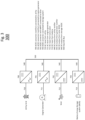
- Fig. 4 illustrates a system 400 having a second stage architecture for an electrolyzer with different power sources according to an example embodiment of the present invention.
- the electrical architecture with different loads from different electrolyzers are connected to one DC bus 550.
- Components of electrolyzers 400.1-400.n are electrically coupled to DC Bus 550 by DC input to segment DCDCs 551 and DC input to heater DCDCs 552, for example.
- Every load is connected to DC bus 550 through an interface DCDC converter.
- the DCDC converters are configured to provide variable voltage between 0 to full rated voltage or to provide variable current between 0 to full rated current depending upon the load requirements.
- the DCDCs also provide galvanic isolation between input and output. Since the electrolyzer stack 201 in each respective electrolyzer 400.1-400.n is grounded, the gasolinic isolation helps avoid ground loops and also helps avoid high fault currents from different circuits passing through the electrolyzer stacks.
- each respective electrolyzer 400.1-400.n can have one or more stacks and one or more stack DCDC converters, multiple heaters (e.g., 202, 203, 204, 20x) and its own DCDCs 12x.
- Multiple DCDCs may be connected to one heater or one DCDC can be connected to multiple heaters depending on the power requirements.
- this architecture enables the removal or addition of electrolyzer units as long as there is enough power on the bus to support the removal or addition of electrolyzers 400.1-400.n. Additionally, this architecture supports the removal or addition of heaters 12x and heater power supplies 20x depending on how heat energy is generated.
- Fig. 5 illustrates a system 500 having two-stage power conversion according to an example embodiment of the present invention.
- the elements of Fig. 5 are the same as those depicted and described in connection with Figs. 1-4 .
- Fig. 6 illustrates power curtailment of stack DCDC 100 and heater DCDC 12x based on DC bus voltage.
Landscapes
- Chemical & Material Sciences (AREA)
- Engineering & Computer Science (AREA)
- Chemical Kinetics & Catalysis (AREA)
- Electrochemistry (AREA)
- Materials Engineering (AREA)
- Metallurgy (AREA)
- Organic Chemistry (AREA)
- Power Engineering (AREA)
- Inorganic Chemistry (AREA)
- Automation & Control Theory (AREA)
- Electrolytic Production Of Non-Metals, Compounds, Apparatuses Therefor (AREA)
- Supply And Distribution Of Alternating Current (AREA)
Applications Claiming Priority (1)
| Application Number | Priority Date | Filing Date | Title |
|---|---|---|---|
| US202263316964P | 2022-03-04 | 2022-03-04 |
Publications (1)
| Publication Number | Publication Date |
|---|---|
| EP4239823A1 true EP4239823A1 (fr) | 2023-09-06 |
Family
ID=85505727
Family Applications (1)
| Application Number | Title | Priority Date | Filing Date |
|---|---|---|---|
| EP23160187.3A Pending EP4239823A1 (fr) | 2022-03-04 | 2023-03-06 | Conversion de puissance d'un électrolyseur |
Country Status (7)
| Country | Link |
|---|---|
| US (1) | US12132322B2 (fr) |
| EP (1) | EP4239823A1 (fr) |
| JP (1) | JP2023129394A (fr) |
| KR (1) | KR20230131153A (fr) |
| CN (1) | CN116695153A (fr) |
| CA (1) | CA3192198A1 (fr) |
| TW (1) | TW202336282A (fr) |
Cited By (1)
| Publication number | Priority date | Publication date | Assignee | Title |
|---|---|---|---|---|
| WO2025106146A3 (fr) * | 2023-09-07 | 2025-09-18 | Lumindt Labs, Inc. | Systèmes et procédés d'énergie employant de l'hydrure métallique à couplage thermique |
Families Citing this family (3)
| Publication number | Priority date | Publication date | Assignee | Title |
|---|---|---|---|---|
| AU2024351373A1 (en) * | 2023-09-27 | 2026-04-02 | Methylennium Energy Corp. | Methods and systems for utilizing intermittent renewable power |
| EP4560050A1 (fr) * | 2023-11-21 | 2025-05-28 | Bloom Energy Corporation | Système de conditionnement de puissance d'électrolyseur et son procédé de commande |
| US20250350111A1 (en) * | 2024-05-10 | 2025-11-13 | TaiLai Ting | Advanced Mobile Power Station with Multi-Source Charging Capability |
Citations (4)
| Publication number | Priority date | Publication date | Assignee | Title |
|---|---|---|---|---|
| WO2019246433A1 (fr) * | 2018-06-20 | 2019-12-26 | Aquahydrex, Inc. | Système de distribution de puissance à courant continu à étages multiples |
| US20210156039A1 (en) * | 2019-11-21 | 2021-05-27 | OHMIUM, Inc. | Modular systems for hydrogen generation and methods of operating thereof |
| US20210317588A1 (en) * | 2018-12-27 | 2021-10-14 | Sma Solar Technology Ag | Electrolysis device having a converter and method for providing instantaneous reserve power for an ac voltage grid |
| US20220065162A1 (en) * | 2020-09-01 | 2022-03-03 | Mitsubishi Power Americas, Inc. | Integrated power production and storage systems |
Family Cites Families (12)
| Publication number | Priority date | Publication date | Assignee | Title |
|---|---|---|---|---|
| US7471010B1 (en) * | 2004-09-29 | 2008-12-30 | Alliance For Sustainable Energy, Llc | Wind turbine tower for storing hydrogen and energy |
| US20080217998A1 (en) * | 2005-02-26 | 2008-09-11 | Parmley Daniel W | Renewable energy power systems |
| US20090179493A1 (en) * | 2008-01-14 | 2009-07-16 | Ming-Hsiang Yeh | Power selection system for heater |
| US8193661B2 (en) * | 2009-02-17 | 2012-06-05 | Lineage Power Corporation | DC plant controller and method for selecting among multiple power sources and DC plant employing the same |
| US8970176B2 (en) * | 2010-11-15 | 2015-03-03 | Bloom Energy Corporation | DC micro-grid |
| US20160241036A1 (en) * | 2012-09-27 | 2016-08-18 | James F. Wolter | Energy apparatuses, energy systems, and energy management methods including energy storage |
| US9471080B2 (en) * | 2013-10-21 | 2016-10-18 | Restore Nv | Portfolio managed, demand-side response system |
| FR3012472B1 (fr) * | 2013-10-25 | 2017-03-31 | Electricite De France | Pilotage d'un electrolyseur a haute temperature |
| US11303130B2 (en) * | 2018-06-14 | 2022-04-12 | Mitsubishi Electric Corporation | Power management system |
| WO2021127156A1 (fr) * | 2019-12-17 | 2021-06-24 | Ohmium International, Inc. | Systèmes et procédés de traitement de l'eau pour la production d'hydrogène |
| DE102020113871A1 (de) * | 2020-05-23 | 2021-11-25 | Sma Solar Technology Ag | Verfahren zur stabilisierung der gleichspannung in einem gleichstromnetz und gleichspannungswandler zur verbindung eines pv-generators mit einem gleichstromnetz |
| TW202400844A (zh) * | 2022-03-04 | 2024-01-01 | 美商博隆能源股份有限公司 | 電解器電力管理及電力系統控制 |
-
2023
- 2023-03-06 EP EP23160187.3A patent/EP4239823A1/fr active Pending
- 2023-03-06 KR KR1020230028978A patent/KR20230131153A/ko active Pending
- 2023-03-06 TW TW112108134A patent/TW202336282A/zh unknown
- 2023-03-06 US US18/178,857 patent/US12132322B2/en active Active
- 2023-03-06 JP JP2023033412A patent/JP2023129394A/ja active Pending
- 2023-03-06 CN CN202310215944.XA patent/CN116695153A/zh active Pending
- 2023-03-06 CA CA3192198A patent/CA3192198A1/fr active Pending
Patent Citations (4)
| Publication number | Priority date | Publication date | Assignee | Title |
|---|---|---|---|---|
| WO2019246433A1 (fr) * | 2018-06-20 | 2019-12-26 | Aquahydrex, Inc. | Système de distribution de puissance à courant continu à étages multiples |
| US20210317588A1 (en) * | 2018-12-27 | 2021-10-14 | Sma Solar Technology Ag | Electrolysis device having a converter and method for providing instantaneous reserve power for an ac voltage grid |
| US20210156039A1 (en) * | 2019-11-21 | 2021-05-27 | OHMIUM, Inc. | Modular systems for hydrogen generation and methods of operating thereof |
| US20220065162A1 (en) * | 2020-09-01 | 2022-03-03 | Mitsubishi Power Americas, Inc. | Integrated power production and storage systems |
Cited By (1)
| Publication number | Priority date | Publication date | Assignee | Title |
|---|---|---|---|---|
| WO2025106146A3 (fr) * | 2023-09-07 | 2025-09-18 | Lumindt Labs, Inc. | Systèmes et procédés d'énergie employant de l'hydrure métallique à couplage thermique |
Also Published As
| Publication number | Publication date |
|---|---|
| KR20230131153A (ko) | 2023-09-12 |
| CA3192198A1 (fr) | 2023-09-04 |
| CN116695153A (zh) | 2023-09-05 |
| JP2023129394A (ja) | 2023-09-14 |
| US12132322B2 (en) | 2024-10-29 |
| TW202336282A (zh) | 2023-09-16 |
| US20230283081A1 (en) | 2023-09-07 |
Similar Documents
| Publication | Publication Date | Title |
|---|---|---|
| EP4239823A1 (fr) | Conversion de puissance d'un électrolyseur | |
| Sanjeev et al. | Peak energy management using renewable integrated DC microgrid | |
| Bai et al. | Distributed generation system control strategies with PV and fuel cell in microgrid operation | |
| US11025062B2 (en) | Apparatus for use in a microgrid and methods of operating the same | |
| Reddy et al. | Utility-interactive hybrid distributed generation scheme with compensation feature | |
| CN110301081B (zh) | 分布式/集中式优化器架构 | |
| Tamalouzt et al. | Wind turbine-DFIG/photovoltaic/fuel cell hybrid power sources system associated with hydrogen storage energy for micro-grid applications | |
| Gowtham et al. | A Management of power flow for DC Microgrid with Solar and Wind Energy Sources | |
| AU2018277085A1 (en) | Control system and method for an energy storage system | |
| Prakash et al. | Intelligent energy management for distributed power plants and battery storage | |
| KR20150085227A (ko) | 에너지 저장 시스템 및 그의 제어 방법 | |
| Luta et al. | Energy management system for a remote renewable fuel cell system | |
| KR101281079B1 (ko) | 전력 품질이 개선된 태양광 발전시스템 및 그 운용 방법 | |
| CN117200289A (zh) | 电力储能系统以及储能供电系统 | |
| Neves et al. | Advantages of grid-tied DC microgrid | |
| Jayalakshmi | Study of hybrid photovoltaic/fuel cell system for stand-alone applications | |
| Dhawad et al. | Analysis of series DC electric spring on negative DC bus for constant resistive and constant power non-critical loads | |
| Rodkin et al. | Control algorithm for hybrid PV-fuel cell energy system | |
| Marinescu et al. | PV-battery system with enhanced control for microgrid integration | |
| Leite et al. | Analysis of the operation of a microgrid with renewable distributed generation | |
| US12567747B2 (en) | Methods to provide electric power from renewable energy equipment to an electrical load | |
| Tejwani et al. | Control strategy for utility interactive hybrid PV Hydrogen System | |
| CN114402525A (zh) | 对来自光伏装置的电力进行供应的光伏优化器电力系统 | |
| Chakraborty et al. | Coordinated Frequency Based Demand Side Management Scheme with Active Power Curtailment of Solar PV in a Battery Hybrid Stand-Alone Microgrid | |
| CN114362257B (zh) | 分布式电源系统 |
Legal Events
| Date | Code | Title | Description |
|---|---|---|---|
| PUAI | Public reference made under article 153(3) epc to a published international application that has entered the european phase |
Free format text: ORIGINAL CODE: 0009012 |
|
| STAA | Information on the status of an ep patent application or granted ep patent |
Free format text: STATUS: THE APPLICATION HAS BEEN PUBLISHED |
|
| AK | Designated contracting states |
Kind code of ref document: A1 Designated state(s): AL AT BE BG CH CY CZ DE DK EE ES FI FR GB GR HR HU IE IS IT LI LT LU LV MC ME MK MT NL NO PL PT RO RS SE SI SK SM TR |
|
| STAA | Information on the status of an ep patent application or granted ep patent |
Free format text: STATUS: REQUEST FOR EXAMINATION WAS MADE |
|
| 17P | Request for examination filed |
Effective date: 20240306 |
|
| RBV | Designated contracting states (corrected) |
Designated state(s): AL AT BE BG CH CY CZ DE DK EE ES FI FR GB GR HR HU IE IS IT LI LT LU LV MC ME MK MT NL NO PL PT RO RS SE SI SK SM TR |