EP4239829A1 - Procédé de charge de batterie d'alimentation, appareil de charge et système de charge - Google Patents
Procédé de charge de batterie d'alimentation, appareil de charge et système de charge Download PDFInfo
- Publication number
- EP4239829A1 EP4239829A1 EP21957185.8A EP21957185A EP4239829A1 EP 4239829 A1 EP4239829 A1 EP 4239829A1 EP 21957185 A EP21957185 A EP 21957185A EP 4239829 A1 EP4239829 A1 EP 4239829A1
- Authority
- EP
- European Patent Office
- Prior art keywords
- energy storage
- converter
- battery
- voltage
- traction battery
- Prior art date
- Legal status (The legal status is an assumption and is not a legal conclusion. Google has not performed a legal analysis and makes no representation as to the accuracy of the status listed.)
- Granted
Links
Images



Classifications
-
- H—ELECTRICITY
- H02—GENERATION; CONVERSION OR DISTRIBUTION OF ELECTRIC POWER
- H02J—ELECTRIC POWER NETWORKS; CIRCUIT ARRANGEMENTS OR SYSTEMS FOR SUPPLYING OR DISTRIBUTING ELECTRIC POWER; SYSTEMS FOR STORING ELECTRIC ENERGY
- H02J7/00—Circuit arrangements for charging or discharging batteries or for supplying loads from batteries
- H02J7/02—Circuit arrangements for charging or discharging batteries or for supplying loads from batteries for charging batteries from AC mains by converters
- H02J7/04—Regulation of charging current or voltage
- H02J7/06—Regulation of charging current or voltage using discharge tubes or semiconductor devices
-
- B—PERFORMING OPERATIONS; TRANSPORTING
- B60—VEHICLES IN GENERAL
- B60L—PROPULSION OF ELECTRICALLY-PROPELLED VEHICLES; SUPPLYING ELECTRIC POWER FOR AUXILIARY EQUIPMENT OF ELECTRICALLY-PROPELLED VEHICLES; ELECTRODYNAMIC BRAKE SYSTEMS FOR VEHICLES IN GENERAL; MAGNETIC SUSPENSION OR LEVITATION FOR VEHICLES; MONITORING OPERATING VARIABLES OF ELECTRICALLY-PROPELLED VEHICLES; ELECTRIC SAFETY DEVICES FOR ELECTRICALLY-PROPELLED VEHICLES
- B60L53/00—Methods of charging batteries, specially adapted for electric vehicles; Charging stations or on-board charging equipment therefor; Exchange of energy storage elements in electric vehicles
- B60L53/60—Monitoring or controlling charging stations
- B60L53/62—Monitoring or controlling charging stations in response to charging parameters, e.g. current, voltage or electrical charge
-
- H—ELECTRICITY
- H02—GENERATION; CONVERSION OR DISTRIBUTION OF ELECTRIC POWER
- H02J—ELECTRIC POWER NETWORKS; CIRCUIT ARRANGEMENTS OR SYSTEMS FOR SUPPLYING OR DISTRIBUTING ELECTRIC POWER; SYSTEMS FOR STORING ELECTRIC ENERGY
- H02J7/00—Circuit arrangements for charging or discharging batteries or for supplying loads from batteries
- H02J7/90—Regulation of charging or discharging current or voltage
- H02J7/96—Regulation of charging or discharging current or voltage in response to battery voltage
-
- B—PERFORMING OPERATIONS; TRANSPORTING
- B60—VEHICLES IN GENERAL
- B60L—PROPULSION OF ELECTRICALLY-PROPELLED VEHICLES; SUPPLYING ELECTRIC POWER FOR AUXILIARY EQUIPMENT OF ELECTRICALLY-PROPELLED VEHICLES; ELECTRODYNAMIC BRAKE SYSTEMS FOR VEHICLES IN GENERAL; MAGNETIC SUSPENSION OR LEVITATION FOR VEHICLES; MONITORING OPERATING VARIABLES OF ELECTRICALLY-PROPELLED VEHICLES; ELECTRIC SAFETY DEVICES FOR ELECTRICALLY-PROPELLED VEHICLES
- B60L53/00—Methods of charging batteries, specially adapted for electric vehicles; Charging stations or on-board charging equipment therefor; Exchange of energy storage elements in electric vehicles
- B60L53/20—Methods of charging batteries, specially adapted for electric vehicles; Charging stations or on-board charging equipment therefor; Exchange of energy storage elements in electric vehicles characterised by converters located in the vehicle
- B60L53/22—Constructional details or arrangements of charging converters specially adapted for charging electric vehicles
-
- B—PERFORMING OPERATIONS; TRANSPORTING
- B60—VEHICLES IN GENERAL
- B60L—PROPULSION OF ELECTRICALLY-PROPELLED VEHICLES; SUPPLYING ELECTRIC POWER FOR AUXILIARY EQUIPMENT OF ELECTRICALLY-PROPELLED VEHICLES; ELECTRODYNAMIC BRAKE SYSTEMS FOR VEHICLES IN GENERAL; MAGNETIC SUSPENSION OR LEVITATION FOR VEHICLES; MONITORING OPERATING VARIABLES OF ELECTRICALLY-PROPELLED VEHICLES; ELECTRIC SAFETY DEVICES FOR ELECTRICALLY-PROPELLED VEHICLES
- B60L53/00—Methods of charging batteries, specially adapted for electric vehicles; Charging stations or on-board charging equipment therefor; Exchange of energy storage elements in electric vehicles
- B60L53/50—Charging stations characterised by energy-storage or power-generation means
- B60L53/53—Batteries
-
- B—PERFORMING OPERATIONS; TRANSPORTING
- B60—VEHICLES IN GENERAL
- B60L—PROPULSION OF ELECTRICALLY-PROPELLED VEHICLES; SUPPLYING ELECTRIC POWER FOR AUXILIARY EQUIPMENT OF ELECTRICALLY-PROPELLED VEHICLES; ELECTRODYNAMIC BRAKE SYSTEMS FOR VEHICLES IN GENERAL; MAGNETIC SUSPENSION OR LEVITATION FOR VEHICLES; MONITORING OPERATING VARIABLES OF ELECTRICALLY-PROPELLED VEHICLES; ELECTRIC SAFETY DEVICES FOR ELECTRICALLY-PROPELLED VEHICLES
- B60L58/00—Methods or circuit arrangements for monitoring or controlling batteries or fuel cells, specially adapted for electric vehicles
- B60L58/10—Methods or circuit arrangements for monitoring or controlling batteries or fuel cells, specially adapted for electric vehicles for monitoring or controlling batteries
- B60L58/12—Methods or circuit arrangements for monitoring or controlling batteries or fuel cells, specially adapted for electric vehicles for monitoring or controlling batteries responding to state of charge [SoC]
-
- B—PERFORMING OPERATIONS; TRANSPORTING
- B60—VEHICLES IN GENERAL
- B60L—PROPULSION OF ELECTRICALLY-PROPELLED VEHICLES; SUPPLYING ELECTRIC POWER FOR AUXILIARY EQUIPMENT OF ELECTRICALLY-PROPELLED VEHICLES; ELECTRODYNAMIC BRAKE SYSTEMS FOR VEHICLES IN GENERAL; MAGNETIC SUSPENSION OR LEVITATION FOR VEHICLES; MONITORING OPERATING VARIABLES OF ELECTRICALLY-PROPELLED VEHICLES; ELECTRIC SAFETY DEVICES FOR ELECTRICALLY-PROPELLED VEHICLES
- B60L58/00—Methods or circuit arrangements for monitoring or controlling batteries or fuel cells, specially adapted for electric vehicles
- B60L58/10—Methods or circuit arrangements for monitoring or controlling batteries or fuel cells, specially adapted for electric vehicles for monitoring or controlling batteries
- B60L58/18—Methods or circuit arrangements for monitoring or controlling batteries or fuel cells, specially adapted for electric vehicles for monitoring or controlling batteries of two or more battery modules
- B60L58/20—Methods or circuit arrangements for monitoring or controlling batteries or fuel cells, specially adapted for electric vehicles for monitoring or controlling batteries of two or more battery modules having different nominal voltages
-
- B—PERFORMING OPERATIONS; TRANSPORTING
- B60—VEHICLES IN GENERAL
- B60L—PROPULSION OF ELECTRICALLY-PROPELLED VEHICLES; SUPPLYING ELECTRIC POWER FOR AUXILIARY EQUIPMENT OF ELECTRICALLY-PROPELLED VEHICLES; ELECTRODYNAMIC BRAKE SYSTEMS FOR VEHICLES IN GENERAL; MAGNETIC SUSPENSION OR LEVITATION FOR VEHICLES; MONITORING OPERATING VARIABLES OF ELECTRICALLY-PROPELLED VEHICLES; ELECTRIC SAFETY DEVICES FOR ELECTRICALLY-PROPELLED VEHICLES
- B60L58/00—Methods or circuit arrangements for monitoring or controlling batteries or fuel cells, specially adapted for electric vehicles
- B60L58/10—Methods or circuit arrangements for monitoring or controlling batteries or fuel cells, specially adapted for electric vehicles for monitoring or controlling batteries
- B60L58/18—Methods or circuit arrangements for monitoring or controlling batteries or fuel cells, specially adapted for electric vehicles for monitoring or controlling batteries of two or more battery modules
- B60L58/21—Methods or circuit arrangements for monitoring or controlling batteries or fuel cells, specially adapted for electric vehicles for monitoring or controlling batteries of two or more battery modules having the same nominal voltage
-
- H—ELECTRICITY
- H02—GENERATION; CONVERSION OR DISTRIBUTION OF ELECTRIC POWER
- H02J—ELECTRIC POWER NETWORKS; CIRCUIT ARRANGEMENTS OR SYSTEMS FOR SUPPLYING OR DISTRIBUTING ELECTRIC POWER; SYSTEMS FOR STORING ELECTRIC ENERGY
- H02J7/00—Circuit arrangements for charging or discharging batteries or for supplying loads from batteries
- H02J7/02—Circuit arrangements for charging or discharging batteries or for supplying loads from batteries for charging batteries from AC mains by converters
- H02J7/04—Regulation of charging current or voltage
-
- H—ELECTRICITY
- H02—GENERATION; CONVERSION OR DISTRIBUTION OF ELECTRIC POWER
- H02J—ELECTRIC POWER NETWORKS; CIRCUIT ARRANGEMENTS OR SYSTEMS FOR SUPPLYING OR DISTRIBUTING ELECTRIC POWER; SYSTEMS FOR STORING ELECTRIC ENERGY
- H02J7/00—Circuit arrangements for charging or discharging batteries or for supplying loads from batteries
- H02J7/34—Parallel operation in networks using both storage and other DC sources, e.g. providing buffering
- H02J7/342—The other DC source being a battery actively interacting with the first one, i.e. battery to battery charging
-
- H—ELECTRICITY
- H02—GENERATION; CONVERSION OR DISTRIBUTION OF ELECTRIC POWER
- H02J—ELECTRIC POWER NETWORKS; CIRCUIT ARRANGEMENTS OR SYSTEMS FOR SUPPLYING OR DISTRIBUTING ELECTRIC POWER; SYSTEMS FOR STORING ELECTRIC ENERGY
- H02J7/00—Circuit arrangements for charging or discharging batteries or for supplying loads from batteries
- H02J7/40—Circuit arrangements for charging or discharging batteries or for supplying loads from batteries characterised by the exchange of charge or discharge related data
- H02J7/42—Circuit arrangements for charging or discharging batteries or for supplying loads from batteries characterised by the exchange of charge or discharge related data with electronic devices having internal batteries, e.g. mobile phones
-
- H—ELECTRICITY
- H02—GENERATION; CONVERSION OR DISTRIBUTION OF ELECTRIC POWER
- H02J—ELECTRIC POWER NETWORKS; CIRCUIT ARRANGEMENTS OR SYSTEMS FOR SUPPLYING OR DISTRIBUTING ELECTRIC POWER; SYSTEMS FOR STORING ELECTRIC ENERGY
- H02J7/00—Circuit arrangements for charging or discharging batteries or for supplying loads from batteries
- H02J7/50—Circuit arrangements for charging or discharging batteries or for supplying loads from batteries acting upon multiple batteries simultaneously or sequentially
- H02J7/52—Circuit arrangements for charging or discharging batteries or for supplying loads from batteries acting upon multiple batteries simultaneously or sequentially for charge balancing, e.g. equalisation of charge between batteries
- H02J7/56—Active balancing, e.g. using capacitor-based, inductor-based or DC-DC converters
-
- H—ELECTRICITY
- H02—GENERATION; CONVERSION OR DISTRIBUTION OF ELECTRIC POWER
- H02J—ELECTRIC POWER NETWORKS; CIRCUIT ARRANGEMENTS OR SYSTEMS FOR SUPPLYING OR DISTRIBUTING ELECTRIC POWER; SYSTEMS FOR STORING ELECTRIC ENERGY
- H02J7/00—Circuit arrangements for charging or discharging batteries or for supplying loads from batteries
- H02J7/50—Circuit arrangements for charging or discharging batteries or for supplying loads from batteries acting upon multiple batteries simultaneously or sequentially
- H02J7/575—Parallel/serial switching of connection of batteries to charge or load circuit
-
- H—ELECTRICITY
- H02—GENERATION; CONVERSION OR DISTRIBUTION OF ELECTRIC POWER
- H02J—ELECTRIC POWER NETWORKS; CIRCUIT ARRANGEMENTS OR SYSTEMS FOR SUPPLYING OR DISTRIBUTING ELECTRIC POWER; SYSTEMS FOR STORING ELECTRIC ENERGY
- H02J7/00—Circuit arrangements for charging or discharging batteries or for supplying loads from batteries
- H02J7/80—Circuit arrangements for charging or discharging batteries or for supplying loads from batteries including monitoring or indicating arrangements
-
- B—PERFORMING OPERATIONS; TRANSPORTING
- B60—VEHICLES IN GENERAL
- B60L—PROPULSION OF ELECTRICALLY-PROPELLED VEHICLES; SUPPLYING ELECTRIC POWER FOR AUXILIARY EQUIPMENT OF ELECTRICALLY-PROPELLED VEHICLES; ELECTRODYNAMIC BRAKE SYSTEMS FOR VEHICLES IN GENERAL; MAGNETIC SUSPENSION OR LEVITATION FOR VEHICLES; MONITORING OPERATING VARIABLES OF ELECTRICALLY-PROPELLED VEHICLES; ELECTRIC SAFETY DEVICES FOR ELECTRICALLY-PROPELLED VEHICLES
- B60L2210/00—Converter types
- B60L2210/10—DC to DC converters
-
- B—PERFORMING OPERATIONS; TRANSPORTING
- B60—VEHICLES IN GENERAL
- B60L—PROPULSION OF ELECTRICALLY-PROPELLED VEHICLES; SUPPLYING ELECTRIC POWER FOR AUXILIARY EQUIPMENT OF ELECTRICALLY-PROPELLED VEHICLES; ELECTRODYNAMIC BRAKE SYSTEMS FOR VEHICLES IN GENERAL; MAGNETIC SUSPENSION OR LEVITATION FOR VEHICLES; MONITORING OPERATING VARIABLES OF ELECTRICALLY-PROPELLED VEHICLES; ELECTRIC SAFETY DEVICES FOR ELECTRICALLY-PROPELLED VEHICLES
- B60L2210/00—Converter types
- B60L2210/30—AC to DC converters
-
- B—PERFORMING OPERATIONS; TRANSPORTING
- B60—VEHICLES IN GENERAL
- B60L—PROPULSION OF ELECTRICALLY-PROPELLED VEHICLES; SUPPLYING ELECTRIC POWER FOR AUXILIARY EQUIPMENT OF ELECTRICALLY-PROPELLED VEHICLES; ELECTRODYNAMIC BRAKE SYSTEMS FOR VEHICLES IN GENERAL; MAGNETIC SUSPENSION OR LEVITATION FOR VEHICLES; MONITORING OPERATING VARIABLES OF ELECTRICALLY-PROPELLED VEHICLES; ELECTRIC SAFETY DEVICES FOR ELECTRICALLY-PROPELLED VEHICLES
- B60L2240/00—Control parameters of input or output; Target parameters
- B60L2240/40—Drive Train control parameters
- B60L2240/52—Drive Train control parameters related to converters
- B60L2240/527—Voltage
-
- B—PERFORMING OPERATIONS; TRANSPORTING
- B60—VEHICLES IN GENERAL
- B60L—PROPULSION OF ELECTRICALLY-PROPELLED VEHICLES; SUPPLYING ELECTRIC POWER FOR AUXILIARY EQUIPMENT OF ELECTRICALLY-PROPELLED VEHICLES; ELECTRODYNAMIC BRAKE SYSTEMS FOR VEHICLES IN GENERAL; MAGNETIC SUSPENSION OR LEVITATION FOR VEHICLES; MONITORING OPERATING VARIABLES OF ELECTRICALLY-PROPELLED VEHICLES; ELECTRIC SAFETY DEVICES FOR ELECTRICALLY-PROPELLED VEHICLES
- B60L2240/00—Control parameters of input or output; Target parameters
- B60L2240/40—Drive Train control parameters
- B60L2240/52—Drive Train control parameters related to converters
- B60L2240/529—Current
-
- B—PERFORMING OPERATIONS; TRANSPORTING
- B60—VEHICLES IN GENERAL
- B60L—PROPULSION OF ELECTRICALLY-PROPELLED VEHICLES; SUPPLYING ELECTRIC POWER FOR AUXILIARY EQUIPMENT OF ELECTRICALLY-PROPELLED VEHICLES; ELECTRODYNAMIC BRAKE SYSTEMS FOR VEHICLES IN GENERAL; MAGNETIC SUSPENSION OR LEVITATION FOR VEHICLES; MONITORING OPERATING VARIABLES OF ELECTRICALLY-PROPELLED VEHICLES; ELECTRIC SAFETY DEVICES FOR ELECTRICALLY-PROPELLED VEHICLES
- B60L2240/00—Control parameters of input or output; Target parameters
- B60L2240/80—Time limits
-
- H—ELECTRICITY
- H02—GENERATION; CONVERSION OR DISTRIBUTION OF ELECTRIC POWER
- H02J—ELECTRIC POWER NETWORKS; CIRCUIT ARRANGEMENTS OR SYSTEMS FOR SUPPLYING OR DISTRIBUTING ELECTRIC POWER; SYSTEMS FOR STORING ELECTRIC ENERGY
- H02J2105/00—Networks for supplying or distributing electric power characterised by their spatial reach or by the load
- H02J2105/30—Networks for supplying or distributing electric power characterised by their spatial reach or by the load the load networks being external to vehicles, i.e. exchanging power with vehicles
- H02J2105/33—Networks for supplying or distributing electric power characterised by their spatial reach or by the load the load networks being external to vehicles, i.e. exchanging power with vehicles exchanging power with road vehicles
- H02J2105/37—Networks for supplying or distributing electric power characterised by their spatial reach or by the load the load networks being external to vehicles, i.e. exchanging power with vehicles exchanging power with road vehicles exchanging power with electric vehicles [EV] or with hybrid electric vehicles [HEV]
-
- H—ELECTRICITY
- H02—GENERATION; CONVERSION OR DISTRIBUTION OF ELECTRIC POWER
- H02J—ELECTRIC POWER NETWORKS; CIRCUIT ARRANGEMENTS OR SYSTEMS FOR SUPPLYING OR DISTRIBUTING ELECTRIC POWER; SYSTEMS FOR STORING ELECTRIC ENERGY
- H02J2207/00—Details of circuit arrangements for charging or discharging batteries or supplying loads from batteries
- H02J2207/20—Charging or discharging characterised by the power electronics converter
-
- Y—GENERAL TAGGING OF NEW TECHNOLOGICAL DEVELOPMENTS; GENERAL TAGGING OF CROSS-SECTIONAL TECHNOLOGIES SPANNING OVER SEVERAL SECTIONS OF THE IPC; TECHNICAL SUBJECTS COVERED BY FORMER USPC CROSS-REFERENCE ART COLLECTIONS [XRACs] AND DIGESTS
- Y02—TECHNOLOGIES OR APPLICATIONS FOR MITIGATION OR ADAPTATION AGAINST CLIMATE CHANGE
- Y02E—REDUCTION OF GREENHOUSE GAS [GHG] EMISSIONS, RELATED TO ENERGY GENERATION, TRANSMISSION OR DISTRIBUTION
- Y02E60/00—Enabling technologies; Technologies with a potential or indirect contribution to GHG emissions mitigation
- Y02E60/10—Energy storage using batteries
-
- Y—GENERAL TAGGING OF NEW TECHNOLOGICAL DEVELOPMENTS; GENERAL TAGGING OF CROSS-SECTIONAL TECHNOLOGIES SPANNING OVER SEVERAL SECTIONS OF THE IPC; TECHNICAL SUBJECTS COVERED BY FORMER USPC CROSS-REFERENCE ART COLLECTIONS [XRACs] AND DIGESTS
- Y02—TECHNOLOGIES OR APPLICATIONS FOR MITIGATION OR ADAPTATION AGAINST CLIMATE CHANGE
- Y02T—CLIMATE CHANGE MITIGATION TECHNOLOGIES RELATED TO TRANSPORTATION
- Y02T90/00—Enabling technologies or technologies with a potential or indirect contribution to GHG emissions mitigation
- Y02T90/10—Technologies relating to charging of electric vehicles
- Y02T90/12—Electric charging stations
Definitions
- This application relates to the field of battery technologies, and in particular, to a charging method, charging apparatus, and charging system for traction battery.
- Embodiments of this application provide a charging method, charging apparatus, and charging system for traction battery, which can improve charging efficiency.
- this application provides a charging method for traction battery, applied to a charging apparatus.
- the charging apparatus includes N energy storage units connected in series, where each energy storage unit includes an energy storage battery and a first DC/DC converter connected to the energy storage battery.
- Each charging period of the charging apparatus includes a stage in which the traction battery is charged and a stage in which the traction battery discharges to the N energy storage units, N being a positive integer greater than 1.
- the charging method includes: in the discharge stage, obtaining a current voltage of the energy storage battery in each energy storage unit; determining, based on the current voltage of the energy storage battery in each energy storage unit, a first voltage output by the first DC/DC converter in each energy storage unit, where the first voltage output by the first DC/DC converter in each energy storage unit is inversely proportional to the current voltage of the energy storage battery in each energy storage unit; and sending a first control signal to the first DC/DC converter in each energy storage unit, where the first control signal is used to control the first DC/DC converter to output the first voltage, so as to cause the energy storage battery in each energy storage unit to receive, at the first voltage via the first DC/DC converter in each energy storage unit, electrical energy released by the traction battery.
- fast charging of the traction battery is implemented by alternate charging and discharging.
- the charging apparatus includes a plurality of energy storage units connected in series, and each energy storage unit includes an energy storage battery and a first DC/DC converter connected to the energy storage battery
- electrical energy discharged by the traction battery to each energy storage unit can be adjusted by controlling output voltage of each first DC/DC converter, for example, adjusting output voltage of the first DC/DC converter in each energy storage unit to be inversely proportional to a current voltage of the energy storage battery.
- This can make electrical energy that each energy storage unit withstands match its current electrical energy, avoiding energy mismatch between the energy storage units. In this way, capacity of the energy storage units is fully used, enabling the energy storage units to more effectively receive the electrical energy released by the traction battery, thereby improving charging efficiency of the traction battery.
- the charging method further includes: in the charge stage, obtaining a current voltage of the energy storage battery in each energy storage unit; determining, based on the current voltage of the energy storage battery in each energy storage unit, a second voltage output by the first DC/DC converter in each energy storage unit, where the second voltage output by the first DC/DC converter in each energy storage unit is proportional to the current voltage of the energy storage battery in the energy storage unit; and sending a second control signal to the first DC/DC converter in each energy storage unit, where the second control signal is used to control the first DC/DC converter to output the second voltage, so as to cause the energy storage battery in each energy storage unit to charge the traction battery at the second voltage via the first DC/DC converter in each energy storage unit.
- output voltage of the first DC/DC converter in each energy storage unit can also be adjusted to be proportional to the current voltage of the energy storage battery, so that electrical energy provided by each energy storage unit better matches current electrical energy of each energy storage unit, further implementing full use of capacity of the energy storage batteries, and improving the charging efficiency of the traction battery.
- the charging apparatus further includes a separating unit.
- the separating unit is connected between the N energy storage units and the traction battery, where the separating unit includes M second DC/DC converters and a switch module connected between the M second DC/DC converters, M being a positive integer greater than or equal to 2.
- the charging method further includes: controlling the switch module to make the M second DC/DC converters connected in series, so that voltage output by the separating unit to the traction battery is M times voltage output by the N energy storage units; or controlling the switch module to make the M second DC/DC converters connected in parallel, so that current output by the separating unit to the traction battery is M times current output by the N energy storage units.
- the foregoing embodiment further provides a separating unit connected between the N energy storage units and the traction battery, where the separating unit includes M second DC/DC converters and a switch module connected between the M second DC/DC converters.
- the switch module can be controlled to change a connection manner between the M second DC/DC converters, thereby implementing adjustment of output side voltage of the separating unit.
- the charging apparatus can charge the traction battery at a high voltage; and when the switch module of the separating unit is controlled to make the M second DC/DC converters connected in parallel, the charging apparatus can charge the traction battery at a high current.
- the charging apparatus further includes an AC/DC converter, where the AC/DC converter is connected between the traction battery and an alternating current power supply.
- the charging method further includes: sending a third control signal to the AC/DC converter, where the third control signal is used to control voltage output by the AC/DC converter to be equal to charging voltage of the traction battery, so as to cause the alternating current power supply to charge the traction battery at the charging voltage via the AC/DC converter.
- the charging method further includes: sending a fourth control signal to the AC/DC converter, where the fourth control signal is used to control voltage output by the AC/DC converter to be equal to discharging voltage of the traction battery, so as to cause the traction battery to discharge to the alternating current power supply at the discharging voltage via the AC/DC converter.
- the AC/DC converter is further connected between the traction battery and the alternating current power supply.
- the AC/DC converter can not only convert alternating current output by the alternating current power supply into stable direct current so as to charge the traction battery, but also convert direct current output by the traction battery into alternating current in the discharge stage of the traction battery, so as to release electrical energy of the traction battery to the alternating current power supply, implementing discharging of the traction battery to the energy storage unit and the alternating current power supply simultaneously. This reduces time of the discharge stage of the traction battery, and further improves the charging efficiency.
- this application provides a charging apparatus for traction battery.
- the charging apparatus includes N energy storage units connected in series and a control module, where each energy storage unit includes an energy storage battery and a first DC/DC converter connected to the energy storage battery.
- Each charging period of the charging apparatus includes a stage in which the traction battery is charged and a stage in which the traction battery discharges to the N energy storage units, N being a positive integer greater than 1.
- the control module is configured to: in the discharge stage, obtain a current voltage of the energy storage battery in each energy storage unit; determine, based on the current voltage of the energy storage battery in each energy storage unit, a first voltage output by the first DC/DC converter in each energy storage unit, where the first voltage output by the first DC/DC converter in each energy storage unit is inversely proportional to the current voltage of the energy storage battery in each energy storage unit; and send a first control signal to the first DC/DC converter in each energy storage unit, where the first control signal is used to control the first DC/DC converter to output the first voltage, so as to cause the energy storage battery in each energy storage unit to receive, at the first voltage via the first DC/DC converter in each energy storage unit, electrical energy released by the traction battery.
- the charging apparatus in the embodiment of this application implements fast charging of the traction battery by alternate charging and discharging. Because the charging apparatus includes a plurality of energy storage units connected in series, and each energy storage unit includes an energy storage battery and a first DC/DC converter connected to the energy storage battery, electrical energy discharged by the traction battery to each energy storage unit can be adjusted by controlling output voltage of each first DC/DC converter, for example, adjusting output voltage of the first DC/DC converter in each energy storage unit to be inversely proportional to a current voltage of the energy storage battery. This can make electrical energy that each energy storage unit withstands match its current electrical energy, avoiding energy mismatch between the energy storage units. In this way, capacity of the energy storage units is fully used, enabling the energy storage units to more effectively receive the electrical energy released by the traction battery, thereby improving the charging efficiency of the traction battery.
- control module is further configured to: in the charge stage, obtain a current voltage of the energy storage battery in each energy storage unit; determine, based on the current voltage of the energy storage battery in each energy storage unit, a second voltage output by the first DC/DC converter in each energy storage unit, where the second voltage output by the first DC/DC converter in each energy storage unit is proportional to the current voltage of the energy storage battery in each energy storage unit; and send a second control signal to the first DC/DC converter in each energy storage unit, where the second control signal is used to control the first DC/DC converter to output the second voltage, so as to cause the energy storage battery in each energy storage unit to charge the traction battery at the second voltage via the first DC/DC converter in each energy storage unit.
- output voltage of the first DC/DC converter in each energy storage unit can also be adjusted to be proportional to the current voltage of the energy storage battery, so that electrical energy provided by each energy storage unit better matches current electrical energy of each energy storage unit, further implementing full use of capacity of the energy storage batteries, and improving the charging efficiency of the traction battery.
- the charging apparatus further includes a separating unit, where the separating unit is connected between the N energy storage units and the traction battery.
- the separating unit includes M second DC/DC converters and a switch module connected between the M second DC/DC converters, M being a positive integer greater than or equal to 2.
- the control module is further configured to: control the switch module to make the M second DC/DC converters connected in series, so that voltage output by the separating unit to the traction battery is M times voltage output by the N energy storage units; or control the switch module to make the M second DC/DC converters connected in parallel, so that current output by the separating unit to the traction battery is M times current output by the N energy storage units.
- the foregoing embodiment provides a separating unit connected between the N energy storage units and the traction battery, where the separating unit includes M second DC/DC converters and a switch module connected between the M second DC/DC converters.
- the switch module can be controlled to change a connection manner between the M second DC/DC converters, thereby implementing adjustment of output side voltage of the separating unit.
- the switch module of the separating unit is controlled to make the M second DC/DC converters connected in series, the traction battery can be charged at a high voltage; and when the switch module of the separating unit is controlled to make the M second DC/DC converters connected in parallel, the traction battery can be charged at a high current.
- the charging apparatus further includes an AC/DC converter, where the AC/DC converter is connected between the traction battery and an alternating current power supply.
- the control module is further configured to send a third control signal to the AC/DC converter, where the third control signal is used to control voltage output by the AC/DC converter to be equal to charging voltage of the traction battery, so as to cause the alternating current power supply to charge the traction battery at the charging voltage via the AC/DC converter.
- control module is further configured to send a fourth control signal to the AC/DC converter, where the fourth control signal is used to control voltage output by the AC/DC converter to be equal to discharging voltage of the traction battery, so as to cause the traction battery to discharge to the alternating current power supply at the discharging voltage via the AC/DC converter.
- the AC/DC converter is further connected between the traction battery and the alternating current power supply.
- the AC/DC converter can not only convert alternating current output by the alternating current power supply into stable direct current so as to charge the traction battery, but also convert direct current output by the traction battery into alternating current in the discharge stage of the traction battery, so as to release electrical energy of the traction battery to the alternating current power supply, implementing discharging of the traction battery to the energy storage unit and the alternating current power supply simultaneously. This reduces time of the discharge stage of the traction battery, and further improves the charging efficiency.
- this application provides an EMS, including a processor, where the processor is configured to perform the method in the first aspect and any one of the possible embodiments of the first aspect.
- an embodiment of this application provides a charging system, including a traction battery and the charging apparatus in the second aspect or any one of the possible embodiments of the second aspect, where the charging apparatus is configured to charge the traction battery, and each charging period includes a stage in which the traction battery is charged and a stage in which the traction battery discharges.
- a traction battery may be used as a major traction source for an electric apparatus such as a vehicle, a ship, or a spacecraft, and an energy storage battery may be a charging source for the electric apparatus.
- an electric apparatus such as a vehicle, a ship, or a spacecraft
- an energy storage battery may be a charging source for the electric apparatus.
- the importance of the traction battery and the energy storage battery is taken for granted.
- the traction battery may be a battery in an electric apparatus
- the energy storage battery may be a battery in a charging apparatus.
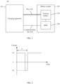
- FIG. 1 is a schematic structural diagram of a charging system to which embodiments of this application are applicable.
- the charging system 100 may include a charging apparatus 100 and a battery system 200.
- the battery system 200 may be a battery system in an electric vehicle (including a battery electric vehicle and a plug-in hybrid electric vehicle) or a battery system in another application scenario.
- the battery system 200 may be provided with at least one battery pack (battery pack), and the at least one battery pack as a whole may be collectively referred to as a traction battery 210.
- the traction battery 210 may be a battery of any type, including but not limited to a lithium-ion battery, a lithium metal battery, a lithium-sulfur battery, a lead-acid battery, a nickel-cadmium battery, a nickel-metal hydride battery, or a lithium-air battery.
- the traction battery 210 in the embodiments of this application may be a cell/battery cell (cell), or may be a battery module or a battery pack, where the battery module or battery pack may be formed by a plurality of batteries connected in series or parallel.
- a specific type and scale of the traction battery 210 are not specifically limited.
- the battery system 200 is generally further provided with a battery management system (battery management system, BMS) 220 for monitoring a state of the traction battery 210.
- BMS battery management system
- the BMS 220 may be integrated with the traction battery 210 in a same device or apparatus, or the BMS 220 may be disposed outside the traction battery 210 as a separate device/apparatus.
- the charging apparatus 100 is an apparatus that supplements electrical energy to the traction battery 210 in the battery system 200.
- the charging apparatus 100 in the embodiments of this application may be a common charging pile, a super charging pile, a charging pile supporting vehicle to grid (vehicle to grid, V2G) mode, a charging apparatus or device capable of charging batteries, or the like.
- V2G vehicle to grid
- a specific type and specific application scenario of the charging apparatus 100 are not limited in the embodiments of this application.
- the charging apparatus 100 may be connected to the traction battery 210 through a wire 300 and connected to the BMS 220 through a communication line 400.
- the communication line 400 is used for information exchange between the charging apparatus 100 and the BMS 220.
- the communication line 400 includes but is not limited to a controller area network (control area network, CAN) communication bus or a daisy chain (daisy chain) communication bus.
- controller area network control area network, CAN
- daisy chain daisy chain
- the charging apparatus 100 can also communicate with the BMS 220 through a wireless network.
- a communication type between the charging apparatus 100 and the BMS 220 is not limited in the embodiments of this application.
- one charging period T includes a stage in which the traction battery 210 is charged and a stage in which the traction battery 210 discharges.
- a charging current is +11; and in the stage in which the traction battery 210 discharges, a charging current is -I2.
- the traction battery 210 discharges so as to release the lithium ions accumulated at the negative electrode of the traction battery 210 during charging, avoiding lithium precipitation, heating, and the like of the traction battery 210. Therefore, the traction battery 210 can be charged at a large current again, thereby implementing fast charging of the traction battery 210.
- the charging apparatus 100 in the embodiments of this application is provided with an energy storage unit, where the energy storage unit is configured to receive electrical energy released by the traction battery 210 in the discharge stage.
- the energy storage unit is, for example, an energy storage battery, where capacity of the energy storage battery directly affects the electrical energy that the traction battery 210 can release.
- the energy storage battery may include a large number of battery cells. When the large number of battery cells are connected in series, if the battery cells have poor consistency, failure of an individual battery cell may lead to failure of the entire energy storage battery, which directly affects charging of the traction battery 210.
- these battery cells may be disposed in a plurality of energy storage batteries, that is, a plurality of energy storage batteries are used to simultaneously receive the electrical energy released by the traction battery 210.
- a battery cell in one energy storage battery fails, in a specified manner, such as bypassing this energy storage battery, it is possible to keep the charging of the traction battery 210 not affected, thereby improving the reliability of charging.
- the plurality of energy storage batteries may be connected in series.
- the possible difference in electrical energy of the plurality of energy storage batteries cause voltage between two ends of each energy storage battery to vary, and currents in the plurality of energy storage batteries connected in series are equal, so electrical energy released by the traction battery 210 to the plurality of energy storage batteries varies.
- an energy storage battery with small state of charge (State of Charge, SOC) has a low voltage between its two ends, therefore within a period of time, the traction battery 210 releases less electrical energy to this energy storage battery; and an energy storage battery with large SOC has a high voltage between its two ends, therefore within the same period of time, the traction battery 210 releases more electrical energy to this energy storage battery.
- SOC state of Charge
- energy mismatch may occur between the energy storage batteries.
- the energy storage battery with small SOC receives less electrical energy; and the energy storage battery with large SOC receives more electrical energy, and can easily be fully charged. Because the plurality of energy storage batteries follow the bucket effect, when one of the energy storage batteries is fully charged, charging of the traction battery 210 is terminated to ensure safety. Therefore, the energy mismatch between the energy storage batteries make the capacity of the energy storage units unable to be fully utilized, so that the charging efficiency of the traction battery 210 cannot be further improved.
- the embodiments of this application propose a charging scheme for traction battery, in which a first DC/DC converter is provided to control charging voltage and discharging voltage of each energy storage battery so that electrical energy received and released by each energy storage battery matches its current capacity, so as to avoid energy mismatch between the energy storage batteries, thereby improving the charging efficiency of the traction battery.
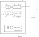
- FIG. 3 is a schematic structural diagram of a charging apparatus 100 according to an embodiment of this application.
- the charging apparatus 100 may be a charging pile or a charger, or may be another type of fixed or mobile charging apparatus. This is no limit herein.
- the charging apparatus 100 may include N energy storage units, for example, an energy storage unit 110 and an energy storage unit 120, N being a positive integer greater than 1.
- Each charging period of the charging apparatus 100 includes a stage in which a traction battery 210 is charged and a stage in which the traction battery 210 discharges to the N energy storage units.
- each energy storage unit includes an energy storage battery and a first DC/DC converter connected to the energy storage battery.
- the energy storage unit 110 includes an energy storage battery 111 and a first DC/DC converter 112 connected to the energy storage battery 111
- the energy storage unit 120 includes an energy storage battery 121 and a first DC/DC converter 122 connected to the energy storage battery 121.
- the energy storage battery in each energy storage unit may be connected in parallel on a first DC side of the first DC/DC converter in this energy storage unit, namely, a side on which a port A and a port B are located, and two electrodes of the energy storage battery may be connected to the port A and port B respectively.
- Second DC sides of the first DC/DC converters in the energy storage units are connected in series, that is, sides on which a port C and a port D are located are connected in series. For example, as shown in FIG.
- the energy storage battery 111 in the energy storage unit 110 is connected in parallel on a first DC side of the first DC/DC converter 112, namely, a side of the first DC/DC converter 112 with a port A and a port B
- the energy storage battery 121 in the energy storage unit 120 is connected in parallel on a first DC side of the first DC/DC converter 122, namely, a side of the first DC/DC converter 122 with a port A and a port B.
- a second DC side of the first DC/DC converter 112 and a second DC side of the first DC/DC converter 122 are connected in series.
- the first DC side of the first DC/DC converter is a side, of the first DC/DC converter, that is used to connect to the energy storage battery
- the second DC side of the first DC/DC converter is a side, of the first DC/DC converter, that is used to connect to the traction battery 210.
- the first DC side is an input side of the first DC/DC converter
- the second DC side is an output side of the first DC/DC converter
- the first DC side is the output side of the first DC/DC converter
- the second DC side is the input side of the first DC/DC converter.
- the first DC/DC converter may be a voltage-type converter that converts input voltage and outputs effective fixed voltage, for example, may be configured as a buck-boost DC/DC converter.
- the N energy storage units may be N single electric boxes, and the energy storage batteries in the N energy storage units may be battery modules or battery packs, where the battery module or battery pack may be formed by a plurality of battery cells connected in series or in parallel.
- the charging apparatus 100 may further include a control unit 160.
- the control unit 160 may be connected to the N energy storage units and is configured to control the first DC/DC converters in the N energy storage units, so that the traction battery 210 discharges to the energy storage units via the first DC/DC converters or the energy storage units charge the traction battery 210 via the first DC/DC converters.
- the control module 160 may further be connected to a BMS 220 of the traction battery 210 through a communication line 400, so as to implement information exchange between the charging apparatus 100 and the BMS 220.
- the control module 160 may be, for example, a charging pile, or an energy management system (energy management system, EMS) in a charger. Further, the control module 160 may further include an auxiliary power supply system.
- EMS energy management system
- FIG. 4 shows a charging method 40 according to an embodiment of this application, used for charging the traction battery 210.
- the method 40 may be performed by the foregoing control module 160, and may specifically include some or all of the following steps.
- Step 410 In a discharge stage, obtain a current voltage of the energy storage battery in each energy storage unit.
- Step 420 Determine, based on a discharging voltage of the traction battery 210, a first voltage output by the first DC/DC converter in each energy storage unit.
- the first voltage output by the first DC/DC converter in each energy storage unit is inversely proportional to the current voltage of the energy storage battery in each energy storage unit.
- Step 430 Send a first control signal to the first DC/DC converter in each energy storage unit.
- the first control signal is used to control the first DC/DC converter to output the first voltage, so as to cause the energy storage battery in each energy storage unit to receive, at the first voltage via the first DC/DC converter in each energy storage unit, electrical energy released by the traction battery 210.
- fast charging of the traction battery 210 is implemented by alternate charging and discharging.
- the charging apparatus 100 includes N energy storage units connected in series, and each energy storage unit includes an energy storage battery and a first DC/DC converter connected to the energy storage battery, electrical energy discharged by the traction battery 210 to each energy storage unit can be adjusted by controlling the output voltage of each first DC/DC converter.
- output voltage of the first DC/DC converter in each energy storage unit is adjusted to be inversely proportional to a current voltage of the energy storage battery, electrical energy that each energy storage unit withstands can match its current electrical energy, avoiding energy mismatch between the energy storage units. This implements full use of capacity of the energy storage units, and enables the energy storage units to more effectively receive the electrical energy released by the traction battery, thereby improving the charging efficiency of the traction battery.
- the control module 160 may receive discharging voltage from the BMS 220, where the discharging voltage is the voltage required for the traction battery 210 to discharge.
- the control module 160 may obtain current voltages of the energy storage batteries in all energy storage units simultaneously, so as to adjust, based on the discharging voltage of the traction battery 210 and the current voltage of each energy storage battery, the first voltage output by the first DC/DC converter in each energy storage unit, to make the first voltage inversely proportional to the current voltage of the energy storage battery in each energy storage unit.
- a sum of voltages of the N energy storage units is equal to the discharging voltage of the traction battery 210.
- the control module 160 controls the first DC/DC converter 112 that is connected to the energy storage battery 111 to output a higher first voltage to the energy storage battery 111; and correspondingly, when the current voltage of the energy storage battery 121 is high, the control module 160 controls the first DC/DC converter 122 that is connected to the energy storage battery 121 to output a lower first voltage to the energy storage battery 122.
- electrical energy received by the energy storage unit can match its current electrical energy
- the energy storage battery 111 with a lower current voltage or less electrical energy can receive more electrical energy from the traction battery 210
- the energy storage battery 112 with a higher current voltage or more electrical energy receives less electrical energy from the traction battery 210, so that energy between the energy storage units is relatively balanced after discharge of the traction battery 210, thereby implementing full use of capacity of the energy storage units and improving charging efficiency.
- control module 160 controls the first DC/DC converter during a stage in which the traction battery 210 discharges to the N energy storage units.
- control module 160 may also control the first DC/DC converter during a stage in which the traction battery 210 is charged by the N energy storage units, so as to make the energy of the N energy storage units more balanced.
- the traction battery 210 may be charged by an alternating current power supply 150 alone, namely, a power grid, or the traction battery 210 may be charged by the N energy storage units and the alternating current power supply 150 together.
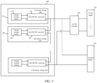
- the charging apparatus 100 further includes an AC/DC converter 140, where the AC/DC converter 140 is connected between the traction battery 210 and the alternating current power supply 150.
- the traction battery 210 is charged, alternating current output by the alternating current power supply 150 is converted into stable direct current via the AC/DC converter 140, so as to charge the traction battery 210.
- the control module 160 may send a third control signal to the AC/DC converter 140, where the third control signal is used to control voltage output by the AC/DC converter 140 to be equal to charging voltage of the traction battery 210, so as to cause the alternating current power supply 150 to charge the traction battery 210 at the charging voltage via the AC/DC converter 140.
- the method 40 may further include:
- electrical energy provided by each energy storage unit to the traction battery 210 can alternatively be adjusted by controlling output voltage of each first DC/DC converter, for example, adjusting output voltage of the first DC/DC converter in each energy storage unit to be proportional to the current voltage of the energy storage battery, so that the energy storage battery with larger SOC transfers more electrical energy to the traction battery 210 and the energy storage battery with smaller SOC transfers less electrical energy to the traction battery 210.
- This can make electrical energy provided by each energy storage unit better match its current electrical energy, and implement full use of capacity of the energy storage batteries, thereby improving the charging efficiency of the traction battery.
- the control module 160 can receive charging voltage from the BMS 220, where this charging voltage is the voltage required for charging the traction battery 210.
- the control module 160 may obtain a current voltage of each energy storage unit and adjust, based on the charging voltage of the traction battery 210 and the current voltage of the energy storage battery in each energy storage unit, the second voltage output by the first DC/DC converter in each energy storage unit to make the second voltage proportional to the current voltage of the energy storage battery in each energy storage unit.
- a sum of voltages of the N energy storage units is equal to the charging voltage of the traction battery 210.
- the charging efficiency is further improved.
- the traction battery 210 can simultaneously discharge to the N energy storage units and the alternating current power supply 150.
- the control module 160 may send a fourth control signal to the AC/DC converter 140, where the fourth control signal is used to control discharging voltage output by the AC/DC converter 140 to be equal to discharging voltage required by the traction battery 210, so as to cause the traction battery 210 to discharge to the alternating current power supply 150 at the discharging voltage via the AC/DC converter 140.
- the traction battery 210 can discharge only to the N energy storage units.
- the AC/DC converter 140 can not only convert alternating current output by the alternating current power supply 150 into stable direct current for the alternating current power supply 150 to charge the traction battery 210, but also convert direct current output by the traction battery 210 into alternating current in the discharge stage of the traction battery 210, so as to release electrical energy of the traction battery 210 to the alternating current power supply 150, implementing discharging of the traction battery 210 to the N energy storage units and the alternating current power supply 150 simultaneously. This reduces time of the discharge stage of the traction battery 210, and further improves the charging efficiency.
- the charging apparatus 100 may further include a separating unit 130.
- the separating unit 130 is connected between the N energy storage units and the traction battery 210, and the separating unit 130 includes M second DC/DC converters and a switch module 133 connected between the M second DC/DC converters, M being a positive integer greater than or equal to 2.
- the control module 160 can control the switch module 133 to make the M second DC/DC converters connected in series.
- voltage output by the separating unit 130 to the traction battery 210 is M times voltage output by the N energy storage units.
- the control module 160 can also control the switch module 133 to make the M second DC/DC converters connected in parallel.
- current output by the separating unit 130 to the traction battery 210 is M times current output by the N energy storage units.
- the separating unit 130 includes two second DC/DC converters: a second DC/DC converter 131 and a second DC/DC converter 132.
- a second DC/DC converter 131 and a second DC/DC converter 132 When the N energy storage units charges the traction battery 210, sides of the second DC/DC converter 131 and the second DC/DC converter 132 that are connected to the N energy storage units serve as input terminals, and sides of the second DC/DC converter 131 and the second DC/DC converter 132 that are connected to the traction battery 210 serve as output terminals.
- the input terminal of the second DC/DC converter 131 and the input terminal of the second DC/DC converter 132 are connected in parallel, and the switch module 133 is connected between the output terminal of the second DC/DC converter 131 and the output terminal of the second DC/DC converter 132.
- the switch module 133 may include a switch K1, a switch K2, and a switch K3.
- the control module 160 may control the switch K1 in the switch module 133 to turn on, so as to make the output terminals of the second DC/DC converter 131 and the second DC/DC converter 132 connected in series.
- voltage output by the separating unit 130 to the traction battery 210 is twice total voltage output by the N energy storage units.
- the control module 160 may control the switch K2 and switch K3 in the switch module 133 to make the output terminals of the second DC/DC converter 131 and the second DC/DC converter 132 connected in parallel. In this way, current output by the separating unit 130 to the traction battery 210 is twice current output by the N energy storage units.
- the separating unit 130 is connected between the N energy storage units and the traction battery 210, and the separating unit 130 includes the M second DC/DC converters and the switch module 133 connected between the M second DC/DC converters, the series or parallel connection relationship of the M second DC/DC converters at the output terminals can be changed by controlling the switch module 133, thereby implementing adjustment of the voltage output by the separating unit 130 to the traction battery 210.
- the switch module 133 of the separating unit 130 When the switch module 133 of the separating unit 130 is controlled to make the M second DC/DC converters connected in series, the traction battery 210 can be charged at a high voltage; and when the switch module 133 of the separating unit 130 is controlled to make the M second DC/DC converters connected in parallel, currents output by the second DC/DC converters are added up, so that the traction battery 210 can be charged at a high current.
- FIG. 7 is a schematic flowchart of a possible implementation based on the charging method shown in FIG. 4 .
- Fast charging of the traction battery 210 can be implemented by periodic charging and discharging of the traction battery 210.
- a method 70 may be performed by the foregoing control module 160, for example, an EMS. Taking the charging apparatus 100 shown in FIG. 5 as an example, the method 70 includes the following steps.
- Step 701. Start charging the traction battery 210 after detecting that the charging apparatus 100 is successfully connected to a battery system 200.
- Step 702. Obtain charging voltage of the traction battery 210 and measure a current voltage of the energy storage battery in each energy storage unit.
- Step 703. Determine output voltage of the first DC/DC converter in each energy storage unit and output voltage of the AC/DC converter 140.
- the output voltage of the AC/DC converter 140 is equal to charging voltage required for the traction battery 210.
- a second voltage output by the first DC/DC converter in each energy storage unit is proportional to the current voltage of the energy storage battery in each energy storage unit.
- Step 704. Send a second control signal to the first DC/DC converter in each energy storage unit.
- the second control signal is used to control the first DC/DC converter to output the second voltage, so as to cause the energy storage battery in each energy storage unit to charge the traction battery 210 at the second voltage via the first DC/DC converter in each energy storage unit.
- Step 704 While Step 704 is being performed, in Step 705, a third control signal is sent to the AC/DC converter 140.
- the third control signal is used to control voltage output by the AC/DC converter 140 to be equal to the charging voltage of the traction battery 210, so as to cause the alternating current power supply 150 to charge the traction battery 210 at the charging voltage.
- Step 706. Determine whether charging is complete.
- the control module 160 receives a charging stop message from the BMS 220. If the charging stop message is received, it is determined that charging is complete, the charging stops, and Step 716 is performed. If no charging stop message is received, it is determined that charging is not complete, and Step 707 is performed.
- Step 707 Record a charging time and determine whether a preset charging time is reached.
- the preset charging time is a time of the charge stage for charging the traction battery 210 in each charging period; and correspondingly, a preset discharging time is a time of the discharge stage for discharging of the traction battery 210 in each charging period.
- the traction battery 210 When the preset charging time is not reached, the traction battery 210 continues to be charged based on the foregoing steps; and when the preset charging time is reached, the discharge stage of this charging period starts.
- Step 708 Obtain discharging voltage of the traction battery 210 and measure a current voltage of the energy storage battery in each energy storage unit.
- Step 709 Determine output voltage of the first DC/DC converter in each energy storage unit and output voltage of the AC/DC converter 140.
- the output voltage of the AC/DC converter 140 is equal to discharging voltage of the traction battery 210.
- a first voltage output by the first DC/DC converter in each energy storage unit is inversely proportional to the current voltage of the energy storage battery in each energy storage unit. In this way, the energy storage battery with larger SOC can receive less electrical energy from the traction battery 210, and the energy storage battery with smaller SOC can receive more electrical energy from the traction battery 210, avoiding energy mismatch between the energy storage batteries, and improving the charging efficiency.
- Step 710 Send a first control signal to the first DC/DC converter in each energy storage unit.
- the first control signal is used to control the first DC/DC converter to output the first voltage, so as to cause the energy storage battery in each energy storage unit to receive, at the first voltage via the first DC/DC converter in each energy storage unit, electrical energy released by the traction battery 210.
- Step 710 it is determined whether the traction battery 210 is allowed to discharge to the alternating current power supply 150.
- Step 712 is performed; otherwise, Step 713 is performed.
- Step 712. Send a stop signal to the AC/DC converter 140.
- the stop signal is used to control the AC/DC converter 140 to turn off.
- Step 713 Send a third control signal to the AC/DC converter 140.
- the third control signal is used to control voltage output by the AC/DC converter 140 to be equal to the discharging voltage of the traction battery 210, so as to cause the alternating current power supply 150 to receive, at the discharging voltage, electrical energy released by the traction battery 210.
- Step 714 Determine whether charging is complete.
- the control module 160 receives a charging stop message from the BMS 220. If the charging stop message is received, it is determined that charging is complete, the charging stops, and Step 716 is performed. If no charging stop message is received, it is determined that charging is not complete, and Step 715 is performed.
- Step 715 Record a charging time and determine whether a preset discharging time is reached.
- the preset discharging time is a time of the discharge stage for discharging of the traction battery 210 in each charging period.
- the traction battery 210 When the preset discharging time is not reached, the traction battery 210 continues to discharge to the N energy storage units based on the foregoing steps; and when the preset discharging time is reached, a charge stage of a next charging period starts.
- Step 716 End charging.
- control module 160 can control electrical energy released or received by the energy storage unit in each energy storage unit by controlling output voltage of each first DC/DC converter in the charge stage and discharge stage, so as to avoid energy mismatch between the energy storage units, thereby implementing full use of capacity of the energy storage units and improving the charging efficiency.
- An embodiment of this application further provides an EMS, including a processor, where the processor is configured to perform the charging method in the foregoing embodiments of this application.
- An embodiment of this application further provides a charging system, characterized by including a traction battery and the charging apparatus 100 described in any one of the foregoing embodiments.
- the charging apparatus 100 is configured to charge the traction battery 210, where each charging period includes a stage in which the traction battery 210 is charged and a stage in which the traction battery 210 discharges.
Landscapes
- Engineering & Computer Science (AREA)
- Power Engineering (AREA)
- Transportation (AREA)
- Mechanical Engineering (AREA)
- Life Sciences & Earth Sciences (AREA)
- Sustainable Development (AREA)
- Sustainable Energy (AREA)
- Charge And Discharge Circuits For Batteries Or The Like (AREA)
Applications Claiming Priority (1)
| Application Number | Priority Date | Filing Date | Title |
|---|---|---|---|
| PCT/CN2021/119453 WO2023039908A1 (fr) | 2021-09-18 | 2021-09-18 | Procédé de charge de batterie d'alimentation, appareil de charge et système de charge |
Publications (4)
| Publication Number | Publication Date |
|---|---|
| EP4239829A1 true EP4239829A1 (fr) | 2023-09-06 |
| EP4239829A4 EP4239829A4 (fr) | 2024-07-03 |
| EP4239829C0 EP4239829C0 (fr) | 2025-07-02 |
| EP4239829B1 EP4239829B1 (fr) | 2025-07-02 |
Family
ID=85602368
Family Applications (1)
| Application Number | Title | Priority Date | Filing Date |
|---|---|---|---|
| EP21957185.8A Active EP4239829B1 (fr) | 2021-09-18 | 2021-09-18 | Procédé de charge de batterie d'alimentation, appareil de charge et système de charge |
Country Status (6)
| Country | Link |
|---|---|
| US (1) | US20230261504A1 (fr) |
| EP (1) | EP4239829B1 (fr) |
| JP (1) | JP7609999B2 (fr) |
| KR (1) | KR102817220B1 (fr) |
| CN (1) | CN116195159B (fr) |
| WO (1) | WO2023039908A1 (fr) |
Families Citing this family (2)
| Publication number | Priority date | Publication date | Assignee | Title |
|---|---|---|---|---|
| KR102913839B1 (ko) * | 2021-09-08 | 2026-01-16 | 컨템포러리 엠퍼렉스 테크놀로지 (홍콩) 리미티드 | 파워 배터리 충전 방법 및 배터리 관리 시스템 |
| JP2025152403A (ja) * | 2024-03-28 | 2025-10-09 | 株式会社東京精密 | 充放電試験システム、充放電試験方法、および、プログラム |
Family Cites Families (11)
| Publication number | Priority date | Publication date | Assignee | Title |
|---|---|---|---|---|
| JP3511927B2 (ja) * | 1999-01-18 | 2004-03-29 | 株式会社日立製作所 | 電力蓄積手段の充放電装置 |
| JP2005057826A (ja) * | 2003-08-01 | 2005-03-03 | Masayuki Hattori | 充放電装置、充放電方法および2次電池の特性評価装置 |
| KR101969301B1 (ko) * | 2013-05-28 | 2019-04-17 | 재단법인 포항산업과학연구원 | Dc 전력 계통용 배터리 충방전 제어 장치 |
| CN203658549U (zh) * | 2013-12-19 | 2014-06-18 | 北汽福田汽车股份有限公司 | 动力电池检测装置及具有其的动力电池检测系统 |
| CN103762703B (zh) * | 2014-02-19 | 2016-04-27 | 国家电网公司 | 电动汽车充储放一体化充电站及充放电方法 |
| CN107769316B (zh) * | 2017-11-03 | 2021-05-11 | 许继电源有限公司 | 一种电池组在线均衡系统及电池 |
| JP2019134635A (ja) * | 2018-02-01 | 2019-08-08 | 住友電気工業株式会社 | 充放電装置及び充放電システム |
| CN109301363B (zh) * | 2018-08-30 | 2025-03-25 | 上汽通用汽车有限公司 | 电池包管理系统、方法及存储介质 |
| CN208813018U (zh) * | 2018-09-10 | 2019-05-03 | 北京稳力科技有限公司 | 一种主动调整式燃料电池车系统 |
| CN109904850B (zh) * | 2019-03-04 | 2021-07-27 | 国网新疆电力有限公司经济技术研究院 | 一种分布式储能直流微电网中储能单元的充放电控制方法 |
| CN113119770B (zh) * | 2021-04-19 | 2024-12-17 | 英飞特电子(杭州)股份有限公司 | 一种充换电系统 |
-
2021
- 2021-09-18 KR KR1020237018881A patent/KR102817220B1/ko active Active
- 2021-09-18 JP JP2023534398A patent/JP7609999B2/ja active Active
- 2021-09-18 WO PCT/CN2021/119453 patent/WO2023039908A1/fr not_active Ceased
- 2021-09-18 CN CN202180047983.2A patent/CN116195159B/zh active Active
- 2021-09-18 EP EP21957185.8A patent/EP4239829B1/fr active Active
-
2023
- 2023-04-26 US US18/139,358 patent/US20230261504A1/en active Pending
Also Published As
| Publication number | Publication date |
|---|---|
| EP4239829A4 (fr) | 2024-07-03 |
| JP2023552787A (ja) | 2023-12-19 |
| US20230261504A1 (en) | 2023-08-17 |
| CN116195159A (zh) | 2023-05-30 |
| CN116195159B (zh) | 2025-08-05 |
| WO2023039908A1 (fr) | 2023-03-23 |
| KR102817220B1 (ko) | 2025-06-09 |
| JP7609999B2 (ja) | 2025-01-07 |
| EP4239829C0 (fr) | 2025-07-02 |
| EP4239829B1 (fr) | 2025-07-02 |
| KR20230107277A (ko) | 2023-07-14 |
Similar Documents
| Publication | Publication Date | Title |
|---|---|---|
| US20230261487A1 (en) | Charging method, charging apparatus, and charging system for traction battery | |
| US12401203B2 (en) | Charging method, battery management system of traction battery and charging pile | |
| EP4220885B1 (fr) | Appareil de charge/décharge, procédé de charge et de décharge de batterie, et système de charge/décharge | |
| KR102801326B1 (ko) | 배터리 충전 방법 및 충방전 장치 | |
| US20260074547A1 (en) | Charging and discharging apparatus and battery charging method | |
| US20230035145A1 (en) | Method for charging battery, battery management system, charge and discharge device | |
| US12374916B2 (en) | Charging method and power conversion apparatus | |
| US20230261504A1 (en) | Charging method, charging apparatus, and charging system for traction battery | |
| EP4152553A1 (fr) | Appareil de charge et de décharge, procédé de charge de batterie et système de charge et de décharge | |
| JP7461385B2 (ja) | 充放電装置、バッテリー充電方法及び充放電システム |
Legal Events
| Date | Code | Title | Description |
|---|---|---|---|
| STAA | Information on the status of an ep patent application or granted ep patent |
Free format text: STATUS: THE INTERNATIONAL PUBLICATION HAS BEEN MADE |
|
| PUAI | Public reference made under article 153(3) epc to a published international application that has entered the european phase |
Free format text: ORIGINAL CODE: 0009012 |
|
| STAA | Information on the status of an ep patent application or granted ep patent |
Free format text: STATUS: REQUEST FOR EXAMINATION WAS MADE |
|
| 17P | Request for examination filed |
Effective date: 20230603 |
|
| AK | Designated contracting states |
Kind code of ref document: A1 Designated state(s): AL AT BE BG CH CY CZ DE DK EE ES FI FR GB GR HR HU IE IS IT LI LT LU LV MC MK MT NL NO PL PT RO RS SE SI SK SM TR |
|
| A4 | Supplementary search report drawn up and despatched |
Effective date: 20240603 |
|
| RIC1 | Information provided on ipc code assigned before grant |
Ipc: H02J 7/00 20060101AFI20240527BHEP |
|
| RAP1 | Party data changed (applicant data changed or rights of an application transferred) |
Owner name: CONTEMPORARY AMPEREX TECHNOLOGY(HONG KONG) LIMITED |
|
| DAV | Request for validation of the european patent (deleted) | ||
| DAX | Request for extension of the european patent (deleted) | ||
| GRAP | Despatch of communication of intention to grant a patent |
Free format text: ORIGINAL CODE: EPIDOSNIGR1 |
|
| STAA | Information on the status of an ep patent application or granted ep patent |
Free format text: STATUS: GRANT OF PATENT IS INTENDED |
|
| INTG | Intention to grant announced |
Effective date: 20250130 |
|
| GRAS | Grant fee paid |
Free format text: ORIGINAL CODE: EPIDOSNIGR3 |
|
| GRAA | (expected) grant |
Free format text: ORIGINAL CODE: 0009210 |
|
| STAA | Information on the status of an ep patent application or granted ep patent |
Free format text: STATUS: THE PATENT HAS BEEN GRANTED |
|
| AK | Designated contracting states |
Kind code of ref document: B1 Designated state(s): AL AT BE BG CH CY CZ DE DK EE ES FI FR GB GR HR HU IE IS IT LI LT LU LV MC MK MT NL NO PL PT RO RS SE SI SK SM TR |
|
| REG | Reference to a national code |
Ref country code: GB Ref legal event code: FG4D |
|
| REG | Reference to a national code |
Ref country code: CH Ref legal event code: EP |
|
| REG | Reference to a national code |
Ref country code: DE Ref legal event code: R096 Ref document number: 602021033615 Country of ref document: DE |
|
| REG | Reference to a national code |
Ref country code: IE Ref legal event code: FG4D |
|
| U01 | Request for unitary effect filed |
Effective date: 20250731 |
|
| U07 | Unitary effect registered |
Designated state(s): AT BE BG DE DK EE FI FR IT LT LU LV MT NL PT RO SE SI Effective date: 20250811 |
|
| U20 | Renewal fee for the european patent with unitary effect paid |
Year of fee payment: 5 Effective date: 20250916 |
|
| PG25 | Lapsed in a contracting state [announced via postgrant information from national office to epo] |
Ref country code: IS Free format text: LAPSE BECAUSE OF FAILURE TO SUBMIT A TRANSLATION OF THE DESCRIPTION OR TO PAY THE FEE WITHIN THE PRESCRIBED TIME-LIMIT Effective date: 20251102 |
|
| PG25 | Lapsed in a contracting state [announced via postgrant information from national office to epo] |
Ref country code: NO Free format text: LAPSE BECAUSE OF FAILURE TO SUBMIT A TRANSLATION OF THE DESCRIPTION OR TO PAY THE FEE WITHIN THE PRESCRIBED TIME-LIMIT Effective date: 20251002 |
|
| PG25 | Lapsed in a contracting state [announced via postgrant information from national office to epo] |
Ref country code: HR Free format text: LAPSE BECAUSE OF FAILURE TO SUBMIT A TRANSLATION OF THE DESCRIPTION OR TO PAY THE FEE WITHIN THE PRESCRIBED TIME-LIMIT Effective date: 20250702 |
|
| PG25 | Lapsed in a contracting state [announced via postgrant information from national office to epo] |
Ref country code: GR Free format text: LAPSE BECAUSE OF FAILURE TO SUBMIT A TRANSLATION OF THE DESCRIPTION OR TO PAY THE FEE WITHIN THE PRESCRIBED TIME-LIMIT Effective date: 20251003 |
|
| PG25 | Lapsed in a contracting state [announced via postgrant information from national office to epo] |
Ref country code: CZ Free format text: LAPSE BECAUSE OF FAILURE TO SUBMIT A TRANSLATION OF THE DESCRIPTION OR TO PAY THE FEE WITHIN THE PRESCRIBED TIME-LIMIT Effective date: 20250702 |
|
| PG25 | Lapsed in a contracting state [announced via postgrant information from national office to epo] |
Ref country code: PL Free format text: LAPSE BECAUSE OF FAILURE TO SUBMIT A TRANSLATION OF THE DESCRIPTION OR TO PAY THE FEE WITHIN THE PRESCRIBED TIME-LIMIT Effective date: 20250702 |
|
| PG25 | Lapsed in a contracting state [announced via postgrant information from national office to epo] |
Ref country code: RS Free format text: LAPSE BECAUSE OF FAILURE TO SUBMIT A TRANSLATION OF THE DESCRIPTION OR TO PAY THE FEE WITHIN THE PRESCRIBED TIME-LIMIT Effective date: 20251002 |
|
| PG25 | Lapsed in a contracting state [announced via postgrant information from national office to epo] |
Ref country code: ES Free format text: LAPSE BECAUSE OF FAILURE TO SUBMIT A TRANSLATION OF THE DESCRIPTION OR TO PAY THE FEE WITHIN THE PRESCRIBED TIME-LIMIT Effective date: 20250702 |
|
| PG25 | Lapsed in a contracting state [announced via postgrant information from national office to epo] |
Ref country code: SM Free format text: LAPSE BECAUSE OF FAILURE TO SUBMIT A TRANSLATION OF THE DESCRIPTION OR TO PAY THE FEE WITHIN THE PRESCRIBED TIME-LIMIT Effective date: 20250702 |
|
| PG25 | Lapsed in a contracting state [announced via postgrant information from national office to epo] |
Ref country code: SK Free format text: LAPSE BECAUSE OF FAILURE TO SUBMIT A TRANSLATION OF THE DESCRIPTION OR TO PAY THE FEE WITHIN THE PRESCRIBED TIME-LIMIT Effective date: 20250702 |