EP4239835A1 - Circuit de secours de soupape motorisé - Google Patents
Circuit de secours de soupape motorisé Download PDFInfo
- Publication number
- EP4239835A1 EP4239835A1 EP23154073.3A EP23154073A EP4239835A1 EP 4239835 A1 EP4239835 A1 EP 4239835A1 EP 23154073 A EP23154073 A EP 23154073A EP 4239835 A1 EP4239835 A1 EP 4239835A1
- Authority
- EP
- European Patent Office
- Prior art keywords
- valve
- control system
- storage means
- move
- energy storage
- Prior art date
- Legal status (The legal status is an assumption and is not a legal conclusion. Google has not performed a legal analysis and makes no representation as to the accuracy of the status listed.)
- Pending
Links
Images


Classifications
-
- F—MECHANICAL ENGINEERING; LIGHTING; HEATING; WEAPONS; BLASTING
- F16—ENGINEERING ELEMENTS AND UNITS; GENERAL MEASURES FOR PRODUCING AND MAINTAINING EFFECTIVE FUNCTIONING OF MACHINES OR INSTALLATIONS; THERMAL INSULATION IN GENERAL
- F16K—VALVES; TAPS; COCKS; ACTUATING-FLOATS; DEVICES FOR VENTING OR AERATING
- F16K31/00—Actuating devices; Operating means; Releasing devices
- F16K31/02—Actuating devices; Operating means; Releasing devices electric; magnetic
- F16K31/04—Actuating devices; Operating means; Releasing devices electric; magnetic using a motor
- F16K31/046—Actuating devices; Operating means; Releasing devices electric; magnetic using a motor with electric means, e.g. electric switches, to control the motor or to control a clutch between the valve and the motor
-
- H—ELECTRICITY
- H02—GENERATION; CONVERSION OR DISTRIBUTION OF ELECTRIC POWER
- H02J—ELECTRIC POWER NETWORKS; CIRCUIT ARRANGEMENTS OR SYSTEMS FOR SUPPLYING OR DISTRIBUTING ELECTRIC POWER; SYSTEMS FOR STORING ELECTRIC ENERGY
- H02J9/00—Circuit arrangements for emergency or stand-by power supply, e.g. for emergency lighting
- H02J9/04—Circuit arrangements for emergency or stand-by power supply, e.g. for emergency lighting in which the distribution system is disconnected from the normal source and connected to a standby source
- H02J9/06—Circuit arrangements for emergency or stand-by power supply, e.g. for emergency lighting in which the distribution system is disconnected from the normal source and connected to a standby source with automatic change-over, e.g. UPS systems
- H02J9/061—Circuit arrangements for emergency or stand-by power supply, e.g. for emergency lighting in which the distribution system is disconnected from the normal source and connected to a standby source with automatic change-over, e.g. UPS systems for DC powered loads
-
- H—ELECTRICITY
- H02—GENERATION; CONVERSION OR DISTRIBUTION OF ELECTRIC POWER
- H02J—ELECTRIC POWER NETWORKS; CIRCUIT ARRANGEMENTS OR SYSTEMS FOR SUPPLYING OR DISTRIBUTING ELECTRIC POWER; SYSTEMS FOR STORING ELECTRIC ENERGY
- H02J50/00—Circuit arrangements or systems for wireless supply or distribution of electric power
- H02J50/001—Energy harvesting or scavenging
-
- H—ELECTRICITY
- H02—GENERATION; CONVERSION OR DISTRIBUTION OF ELECTRIC POWER
- H02J—ELECTRIC POWER NETWORKS; CIRCUIT ARRANGEMENTS OR SYSTEMS FOR SUPPLYING OR DISTRIBUTING ELECTRIC POWER; SYSTEMS FOR STORING ELECTRIC ENERGY
- H02J7/00—Circuit arrangements for charging or discharging batteries or for supplying loads from batteries
- H02J7/34—Parallel operation in networks using both storage and other DC sources, e.g. providing buffering
-
- H—ELECTRICITY
- H02—GENERATION; CONVERSION OR DISTRIBUTION OF ELECTRIC POWER
- H02J—ELECTRIC POWER NETWORKS; CIRCUIT ARRANGEMENTS OR SYSTEMS FOR SUPPLYING OR DISTRIBUTING ELECTRIC POWER; SYSTEMS FOR STORING ELECTRIC ENERGY
- H02J7/00—Circuit arrangements for charging or discharging batteries or for supplying loads from batteries
- H02J7/34—Parallel operation in networks using both storage and other DC sources, e.g. providing buffering
- H02J7/345—Parallel operation in networks using both storage and other DC sources, e.g. providing buffering using capacitors as storage or buffering devices
-
- H—ELECTRICITY
- H02—GENERATION; CONVERSION OR DISTRIBUTION OF ELECTRIC POWER
- H02J—ELECTRIC POWER NETWORKS; CIRCUIT ARRANGEMENTS OR SYSTEMS FOR SUPPLYING OR DISTRIBUTING ELECTRIC POWER; SYSTEMS FOR STORING ELECTRIC ENERGY
- H02J7/00—Circuit arrangements for charging or discharging batteries or for supplying loads from batteries
- H02J7/855—Circuit arrangements for charging or discharging batteries or for supplying loads from batteries with circuits adapted for supplying loads from the battery
-
- F—MECHANICAL ENGINEERING; LIGHTING; HEATING; WEAPONS; BLASTING
- F16—ENGINEERING ELEMENTS AND UNITS; GENERAL MEASURES FOR PRODUCING AND MAINTAINING EFFECTIVE FUNCTIONING OF MACHINES OR INSTALLATIONS; THERMAL INSULATION IN GENERAL
- F16K—VALVES; TAPS; COCKS; ACTUATING-FLOATS; DEVICES FOR VENTING OR AERATING
- F16K31/00—Actuating devices; Operating means; Releasing devices
- F16K31/02—Actuating devices; Operating means; Releasing devices electric; magnetic
- F16K31/04—Actuating devices; Operating means; Releasing devices electric; magnetic using a motor
-
- H—ELECTRICITY
- H02—GENERATION; CONVERSION OR DISTRIBUTION OF ELECTRIC POWER
- H02J—ELECTRIC POWER NETWORKS; CIRCUIT ARRANGEMENTS OR SYSTEMS FOR SUPPLYING OR DISTRIBUTING ELECTRIC POWER; SYSTEMS FOR STORING ELECTRIC ENERGY
- H02J2207/00—Details of circuit arrangements for charging or discharging batteries or supplying loads from batteries
- H02J2207/10—Control circuit supply, e.g. means for supplying power to the control circuit
-
- H—ELECTRICITY
- H02—GENERATION; CONVERSION OR DISTRIBUTION OF ELECTRIC POWER
- H02J—ELECTRIC POWER NETWORKS; CIRCUIT ARRANGEMENTS OR SYSTEMS FOR SUPPLYING OR DISTRIBUTING ELECTRIC POWER; SYSTEMS FOR STORING ELECTRIC ENERGY
- H02J2207/00—Details of circuit arrangements for charging or discharging batteries or supplying loads from batteries
- H02J2207/50—Charging of capacitors, supercapacitors, ultra-capacitors or double layer capacitors
Definitions
- the technology described herein relates to the operation and control of motorised valves, and in particular to backup systems for motorised valves.
- Motorised valves are electrically controlled valves. These are often used for controlling fluid flow, and are increasingly used for aerospace applications, especially with the current drive towards more electric aircraft (MEA).
- MEA electric aircraft
- An example of this is for toilet or waste-water systems on-board aircraft, where the valve is used to control the flow of water to the system.
- a problem that may exist with such motorised valve is that the electrical control system may fail. In that case, if the valve were left in an open position, for example, there may be an uncontrolled water flow. This can result in incomplete drainage, and eventually an overflow of the toilet or waste tank, which can in turn lead to damage to the system or the environment that the system is installed in.
- an emergency backup system that is operable to return the valve to a desired safe state (e.g. a closed position) in the event of a failure of the control system.
- a desired safe state e.g. a closed position
- Existing emergency backup systems may however be relatively bulky which may render them less suitable for aircraft applications.
- a first aspect of the technology described herein comprises a control system for a motorised valve, the control system comprising:
- the backup circuit is arranged and configured such that the energy harvesting circuit is operable to harvest sufficient energy within the minimum duration for a single actuation pulse provided by the motor controller along the first power supply line to charge the energy storage means from zero to a sufficient level to allow the backup circuit to generate at least one corresponding discharge actuation pulse at the desired second voltage level for causing the valve to move to the second position.
- the above arrangement provides an improved control system for a motorised valve.
- the motorised valve is provided with a backup circuit that is capable of automatically moving the valve to a second (safe, e.g. closed) position, e.g. in the event of a power failure.
- the backup circuit is therefore in embodiments operable as an emergency backup circuit to provide higher functional safety, as will be explained further below.
- this backup functionality can be achieved using a relatively smaller, lighter weight circuit, that is therefore particularly suited for use on-board aircraft.
- the backup circuit is operable to harvest energy from the power supply lines between the motor controller and the valve each time the motor controller provides an actuation pulse to the valve for causing the valve to change position.
- an actuation pulse is a transient power signal that is provided to the valve to cause the valve (i.e. an element of the valve) to move position.
- the actuation pulse is therefore a power pulse that provides power to the valve to cause the change in valve position.
- An actuation pulse may have a relatively short duration, e.g. corresponding to the time taken to move the valve between positions.
- a typical actuation pulse may have a duration of between about 0.5 and 1.5 seconds, this being the minimum duration required for causing the valve to move position.
- the backup circuit is powered (charged) by the motor controller during normal motor controller operation.
- the backup circuit is designed such that the energy harvesting circuit is capable of harvesting sufficient energy from a single first actuation pulse, i.e. during a single instance of the motor controller actuating the valve to a first (e.g. open) position, to allow the backup circuit to be able to produce one or more corresponding second actuation pulse to return the valve to a second (safe, e.g. closed) position.
- the actuation pulses provided by the motor controller are each associated with a (minimum) duration corresponding to a time required for causing the valve to move to the first position.
- the minimum duration would correspond to the shortest time required for moving the valve from the second position to the first position.
- the minimum duration may be the shortest time taken to move the valve into the first position from one of the other available positions.
- the backup circuit is designed, and its components suitably arranged and selected, to facilitate such rapid charging of the energy storage means from a single actuation pulse ('single-shot' charging), such that the backup circuit is effectively self-sufficient, and can always move the valve to the second (safe, e.g. closed) position following an (each) activation of the valve to the first (e.g. open) position by the motor controller.
- the backup circuit is powered only by harvesting energy from the power supply lines during normal use, without therefore requiring any additional external backup power supply.
- the energy storage means may not be at zero for most of the time, such that most of the time it will not need to be charged from zero.
- the above arrangements provide a failsafe mechanism where the emergency backup is designed such that the energy storage means can be charged from zero to the desired level within the minimum actuation pulse duration. That this effect is achieved can readily be verified by suitably testing the motor controller, e.g. by first discharging the energy storage means to zero, and then providing an actuation pulse, and harvesting energy therefrom, in order to re-charge the energy storage means, accordingly.
- the motor controller is operable to provide first actuation pulses along the first power supply line to cause the valve to move to a first, e.g. open, position. That is, when it is desired to move the valve to the first (e.g. open) position, a corresponding first actuation pulse can be provided by the motor controller, and passed along the first power supply line to the valve.
- the motor controller further comprises a second power supply line, along which the motor controller can provide corresponding actuation pulses to cause the valve to move to a second, e.g. closed, position.
- the motor controller may provide respective power pulses along the first and second power supply lines in order to move the valve between the first (e.g. open) and second (safe, e.g. closed) positions, as desired.
- the valve may also be moveable to third or further positions, in which case corresponding third or further power supply lines and signals may be provided.
- the second position need not necessarily be a 'closed' position but may be any other 'safe' position where the flows are suitably controlled, e.g. to avoid risk of damage to the system within which the valve is operated.
- the valve may have multiple positions, and the first and second positions may be any suitable positions from the available positions.
- the normal valve operation is controlled by the motor controller (only), e.g. in the normal manner for controlling a valve.
- the backup circuit in the event of a power failure, can thus be triggered to discharge the energy storage means through the discharge gate in order to generate an appropriate pulse to cause the valve to move to the second (safe, e.g. closed) position.
- the backup circuit in embodiments can thus be triggered in such circumstances to produce a discharge pulse that is analogous to the actuation pulses that would normally be provided by the motor controller (e.g. the actuation pulses provided along the second power supply line, where that is provided, to cause the valve to move to the second (safe, e.g. closed) position).
- control system further comprises a monitoring circuit that is operable to monitor for power failure and/or other such faults that mean that the motor controller is not able to control the position of the valve.
- the backup circuit can then be (and is) triggered to discharge the energy storage means to produce a second actuation pulse to cause the valve to move to the second (safe, e.g. closed) position.
- the control system is always able to move the valve to the second (safe, e.g. closed) position, even in the event of a failure of the motor controller.
- the control system implements a timeout function, such that in response to the monitoring circuit detecting a power failure, the control system is configured to wait for a predetermined period before triggering the backup circuit discharge to cause the valve to move to the second (safe, e.g. closed) position.
- a pre-set delay before triggering the discharge of the energy storage means. This delay may be set appropriately, e.g. depending on the valve operation in question.
- the backup circuit may be triggered to cause the valve to move to the second (safe, e.g. closed) position after a predetermined time period has elapsed, e.g. in response to the absence of a positive signal from the motor controller to move the valve to the second (safe, e.g. closed) position. That is, if no second signal has been received from the motor controller within an expected time period, the control system may determine on that basis that an error has occurred, and automatically trigger the backup circuit to move the valve to the second (safe, e.g. closed) position.
- the backup circuit could always be used to return the valve to the second (safe, e.g. closed) position, even in normal operation. That is, in some embodiments, the motor controller may be configured only to move the valve to the first (e.g. open) position, with the backup circuit always being used to then move the valve (back) to the second (safe, e.g. closed) position.
- This can provide an overall simpler arrangement, e.g. with a single power supply line control to move the valve to a first (e.g. open) and automatic return of the valve to a second (e.g. closed) position.
- Various other arrangements would be possible in that regard.
- the backup circuit comprises energy storage means. These may take any suitable and desired form.
- the energy storage means is rechargeable.
- the energy storage means comprises one or more capacitors, and in embodiments, a bank of plural capacitors. Where there are plural capacitors these may be arranged in any suitable and desired fashion.
- the capacitors are arranged in parallel. In embodiments, these capacitors are supercapacitors.
- the use of supercapacitors may be particularly advantageous in the context of the technology described herein due to their high capacity to size ratio, and tolerance for repeated discharge.
- the supercapacitors are relatively lower voltage supercapacitors (e.g. voltage rated 1-5 VDC, such as 3.3 VDC). This helps facilitate reducing the size and bulk of the energy storage means, as will be explained further below.
- the backup circuit further comprises a discharge gate through which the energy storage means can be discharged.
- the discharge gate is thus operatively connected to the valve to provide actuation pulses to the valve to cause the valve to move position.
- the backup circuit may generally be configured to provide similar actuation pulses as those that would otherwise (normally) be provided by the motor controller to cause the valve to move position.
- the discharge gate may thus be connected to a power supply line to the valve in order to inject pulses onto one or more of the power supply lines to cause the valve to move position.
- the discharge gate may be connected to the (e.g.) second power supply line (where this is provided) in order to inject discharge pulses that are analogous to the corresponding actuation pulses that would be provided by the motor controller to move the valve to the second (safe, e.g. closed) position in normal operation.
- the actuation pulses provided by the motor controller may be provided at a first voltage level, e.g. determined by the system within which the valve is installed.
- the first voltage level may be 28 VDC, since this is the standard voltage bus level within an aircraft.
- other suitable voltage levels may be used, as desired.
- the second actuation pulses that are provided to the valve by the backup circuit should also be provided at a similar voltage level to the actuation pulses provided by the motor controller, or at least a sufficiently high voltage level, in order to be able to control the valve position in a similar fashion.
- the second actuation pulses provided by the backup circuit are provided at the first voltage level (e.g. 28 VDC).
- the first voltage level e.g. 28 VDC
- the second actuation pulses provided by the backup circuit are provided at a lower voltage level than the pulses provided by the motor controller. That is, the second voltage level may be less than or equal to the first voltage level.
- the second actuation pulses provided by the backup circuit are in embodiments provided at an output level of between 18 and 28 VDC.
- the energy storage means of the backup circuit could be selected to provide the desired output level (e.g. 18-28 VDC). However, this would typically require relatively large and bulky energy storage means. Furthermore, such large energy storage means could not then be easily and rapidly charged to the desired level. This would therefore not provide the desired single-shot charging that is achieved by the technology described herein.
- the energy storage means has a lower voltage rating than the first voltage level (the voltage level at which the actuation pulses are provided by the motor controller). This then means that the energy storage means can be more rapidly charged and thus facilitates charging the energy storage means using energy harvested from the power supply lines in use.
- the backup circuit components are arranged and sized to allow the energy storage means to be sufficiently charged from a single actuation pulse provided by the motor controller.
- the energy storage means in the technology described herein is thus charged by harvesting energy from the power supply lines, e.g. during normal operation.
- the energy harvesting circuit may thus be connected to at least the first power supply line so as to harvest energy therefrom for charging the energy storage means.
- the energy harvesting circuit is also connected to the second, and any further, power supply lines and is operable to harvest energy from pulses provided along any of the power supply lines.
- the backup circuit is operable such that a single actuation pulse provided by the motor controller is able to charge the energy storage means from zero to a sufficient level to allow the backup circuit to produce a corresponding one or more pulses to move the valve to a second (safe, e.g. closed) position.
- This can be achieved by suitably under sizing the energy storage means, e.g. by using lower voltage rated energy storage means, to facilitate a more rapid charging from the power supply lines during normal operation.
- the energy storage means may be sufficiently charged within the time period associated with a single actuation pulse provided by the motor controller.
- the energy storage means may be sufficiently charged within a time period of between about 0.5 and 1.5 seconds.
- the energy storage means comprises one or more capacitors.
- the lower voltage rating thus means that the capacitors can be relatively smaller in size compared to higher voltage rated capacitors.
- the capacitors may be rated for 3.3 VDC operation. This is much lower than the typical voltage level that the actuation signals are provided. For example, when used in aircraft applications, the desired voltage level for the actuation pulses is 28 VDC, which is roughly 8 times higher than the capacitor output.
- the energy storage means can therefore be undersized, and lower voltage-rated, and hence more rapidly charged, e.g. in a 'single-shot' manner, as described above.
- this single-shot charging means that the backup circuit is effectively always capable of moving the valve back to the second (safe, e.g. closed) position, since it can be sufficiently charged from the first actuation pulse. This then avoids the need, e.g., to directly charge the backup circuit from an external power supply, thus further reducing the size and bulk of the overall control system.
- the relatively smaller size of the energy storage means further allows the backup circuit to be attached or embedded within an existing PCB or valve housing, thus facilitating manufacture and installation.
- the energy harvesting circuit may therefore comprise a step down circuit for stepping down the voltage between the power supply lines and the energy storage means to a desired (lower) level for charging the energy storage means.
- This step down circuit may be implemented in any suitable and desired manner.
- the backup circuit further comprises a step up circuit for stepping up the voltage output of the energy storage means to the desired voltage level.
- the step up circuit may take any suitable and desired form. This then allows the second actuation pulses that are produced by discharging the energy storage means to be stepped up to a desired level for actuating the valve, e.g., and in embodiments, to a similar (e.g. 18-28 VDC) voltage level as the actuation pulses provided by the motor controller.
- the step up circuit should thus be configured for stepping up the voltages appropriately.
- the overall operation of the backup circuit may be controlled in any suitable manner.
- a microcontroller is provided that is operable to control the charging and discharging of the energy storage means in the manner described above. Any suitable and desired microcontroller may be used for this purpose.
- the overall control of the backup circuit may generally be performed in other manners, including either in hardware or embedded software, as desired. Various arrangements would be possible in this regard.
- the control system can be incorporated within a motorised valve system comprising the control system and a motorised valve.
- the motorised valve system may be used for any suitable purpose.
- the technology described herein may be particularly suited for applications on-board an aircraft. This may include, for example, for controlling toilet and/or waste water systems on-board the aircraft. Various other examples would of course be possible.
- a second aspect of the technology described herein therefore comprises a method of operating a motorised valve using the control system according to any embodiments of the first aspect described above.
- the method may thus comprise, during normal operation, controlling the valve using the motor controller by providing first actuation pulses to move the valve to the first position; whereas in response to a failure of the motor controller, the method comprises producing a second actuation pulse by discharging the backup circuit through the discharge gate to move the valve to the second position.
- control system that is used in this second aspect may thus have any or all of the optional features described above, at least to the extent they are not mutually exclusive.
- Motorised valves may find application in various situations. For example, they may be used on-board aircraft for toilet and waste water systems.
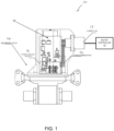
- a motorised valve assembly 10 may include a motorized valve 14 and a connector 18.
- the connector 18 may connect the motorised valve assembly 10 to (e.g.) a motor controller 12 that is arranged to provide power drawn from an aircraft electrical distribution network to the motorized valve 14.
- the motorised valve 14 may include further electronics 13 embedded in the motorised valve 14 for control (e.g. positioning control) over the motor in the valve, but this will not be described in further detail.
- control e.g. positioning control
- the motorised valve assembly 10 may generally have any suitable and desired configuration.
- control system of the technology described herein may generally be applied to any suitable valve arrangement, as desired.
- any suitable valve arrangement as desired.
- the technology described herein may be applied to other (e.g. multidirectional) valve arrangements.
- FIG 2 shows a control system for a motorised valve according to an embodiment that comprises a backup circuit in the form of power backup module 16.
- the power backup module 16 is designed to fit inside the motorised valve assembly 10 case.
- the backup module 16 may be mechanically and/or electronically attached to the electronics 13, or may be a part of the same circuit board as the electronics 13. Indeed, a benefit of the control system according to embodiments is that it can be made relatively smaller and lighter weight to facilitate such installation.
- the control system includes first and second power supply lines 18A, 18B that provide respective signals to the valve to cause the valve to move to the open or closed positions.
- the power supply lines 18A, 18B are independent.
- the motor controller 12 sends signals along the respective power supply lines 18A, 18B in order to control the opening/closing of the valve 14. For instance, in order to open the valve, a first actuation signal (pulse) is sent along the first power supply line 18A.
- a corresponding actuation signal (pulse) is sent along the second power supply line 18B.
- these power control signals are provided at 28 VDC, which is typical for electrical systems within aircraft. Other arrangements would however be possible.
- the control system further comprises the power backup module 16.
- the power backup module 16 is arranged to control the valve position in the event of a power failure, or other such failure, that means that the motor controller 12 is unable to control the valve properly.
- the power backup module 16 comprises a microcontroller unit (MCU) 22 for controlling the overall backup operation, a charging controller 23 for controlling charging of a supercapacitor bank 24, and a discharge gate 28.
- the first power supply line 18A is directly connected to the valve 14 (which may include further embedded electronics for 'local' motor control, not shown in Figure 2 ).
- the discharge gate 28 is connected to the second power supply line 18B, such that the power backup module 16 is operable to inject pulses onto the second power supply line 18B to cause the valve to close, e.g. in response to the MCU 22 detecting a power loss in the system that means that the valve may otherwise be stuck in the open system.
- the MCU 22 keeps the discharge gate 28 closed, so that signals pass directly from the motor controller 12 along the respective power supply lines 18A, 18B.
- the MCU 22 can then initiate a discharge control, wherein the MCU 22 opens the discharge gate 28 and triggers a discharge of the supercapacitor bank 24 through the discharge gate 28 to inject a pulse onto the second power supply line 18B to cause the valve to close.
- the MCU 22 is configured to wait for a predetermined period before activating the discharge gate to close the valve.
- the MCU 22 may implement a timer (timeout) function to prevent the valve from immediately closing, even in the event of a power loss detection. In that case the valve is open for a specific time to let the water flow through to flush clean the toilet. If, after the timer has expired, no additional signal has been provided along the second power supply line 18B, the MCU 22 then opens the discharge gate 28 and triggers the discharge of the supercapacitor bank 24 through the discharge gate 28 to close the valve and achieve safe position.
- a timer timeout
- the supercapacitors in the supercapacitor bank 24 are low voltage rated.
- the supercapacitors are rated at 3.3 VDC, much lower than the voltage level used by the motorised valve system 10 (i.e. 28 VDC).
- the discharge gate 28 is thus provided with a DC-DC step-up discharge circuit that is configured to step up the 3.3 VDC output of the supercapacitor bank 24 to a suitable level (e.g. in the range 18 - 28 VDC) for closing the valve.
- a suitable level e.g. in the range 18 - 28 VDC
- the 3.3 VDC output from the supercapacitor bank 24 is stepped up to 18 VDC, which has been found sufficient to close the valve.
- the use of lower rated capacitors in turn also facilitates a more rapid charging of the supercapacitor bank 24.
- the power backup module 16 is charged during normal operation of the valve by harvesting energy from both of the power supply lines 18A, 18B through power harvesting lines 20.
- the motor controller provides a signal to the valve along either of these power supply lines 18A, 18B some of the energy is harvested through power harvesting lines 20 and used by the MCU 22 to trigger the charging control circuit 23 to charge the supercapacitor bank 24.
- the charging control circuit 23 provides the charging power signals to the supercapacitor bank 24.
- the charging control circuit 23 may also monitor the temperature and/or charging status, etc., in order to control the charging operation.
- a step down circuit is thus provided in the form of DC-DC step down charger 27 that is operable to step down the 28 VDC signals from the power supply lines 18A, 18B to a suitably low level (e.g. 3,3 VDC in this example) for safely charging the supercapacitor bank 24.
- a suitably low level e.g. 3,3 VDC in this example
- the power backup module 16 is designed such that a single actuation pulse provided along the first power supply line 18A is able to charge the supercapacitor bank 24 sufficiently such that the power backup module 16 can then generate multiple signals for closing the valve.
- Figures 3 and 4 show the results of proof of concept testing for the above arrangement.
- the motor controller operates at 28 VDC
- the energy storage means comprises a bank of supercapacitors that provide a voltage output of 3.3 VDC.
- the energy storage means comprised a bank of four supercapacitors, arranged in parallel.
- the step up circuit was arranged to step this voltage output up to 18 VDC.
- Figures 3 and 4 confirm that a control system according to the technology described herein can work well to provide a higher safety motorised valve control with a relatively simpler, lower weight design.
- FIGS 3 and 4 merely show the results for one example of a control system according to the technology described herein, and those skilled in the art will recognise that the specific values mentioned above may be varied, as desired, e.g. depending on the valve application in question, whilst still providing the benefits of the technology described herein. That is, those skilled in the art will appreciate how to select appropriate components based (e.g.) on the desired voltage level and desired charging time for designing a backup circuit that is able to operate in the manner described herein.
Landscapes
- Engineering & Computer Science (AREA)
- Power Engineering (AREA)
- General Engineering & Computer Science (AREA)
- Mechanical Engineering (AREA)
- Business, Economics & Management (AREA)
- Emergency Management (AREA)
- Computer Networks & Wireless Communication (AREA)
- Electrically Driven Valve-Operating Means (AREA)
Priority Applications (1)
| Application Number | Priority Date | Filing Date | Title |
|---|---|---|---|
| US18/174,529 US12287043B2 (en) | 2022-03-03 | 2023-02-24 | Motorized valve backup circuit |
Applications Claiming Priority (1)
| Application Number | Priority Date | Filing Date | Title |
|---|---|---|---|
| EP22461519 | 2022-03-03 |
Publications (1)
| Publication Number | Publication Date |
|---|---|
| EP4239835A1 true EP4239835A1 (fr) | 2023-09-06 |
Family
ID=80628518
Family Applications (1)
| Application Number | Title | Priority Date | Filing Date |
|---|---|---|---|
| EP23154073.3A Pending EP4239835A1 (fr) | 2022-03-03 | 2023-01-30 | Circuit de secours de soupape motorisé |
Country Status (2)
| Country | Link |
|---|---|
| US (1) | US12287043B2 (fr) |
| EP (1) | EP4239835A1 (fr) |
Citations (2)
| Publication number | Priority date | Publication date | Assignee | Title |
|---|---|---|---|---|
| US20100007301A1 (en) * | 2006-05-24 | 2010-01-14 | Belimo Holding Ag | Safety drive for a flap or a valve |
| US20190049036A1 (en) * | 2017-08-08 | 2019-02-14 | Azbil Corporation | Electric actuator with priortized charging for electric valve return |
Family Cites Families (7)
| Publication number | Priority date | Publication date | Assignee | Title |
|---|---|---|---|---|
| WO2004025820A1 (fr) * | 2002-09-13 | 2004-03-25 | Tokyo Electron Limited | Dispositif de commande de rotation et procede de commande de rotation |
| US20110267068A1 (en) * | 2010-05-03 | 2011-11-03 | Jian Xu | Energy storage level indication circuit |
| US9379577B2 (en) | 2012-08-30 | 2016-06-28 | Honeywell International Inc. | Capacitive power system having a service life extending approach |
| WO2016131472A1 (fr) | 2015-02-16 | 2016-08-25 | Oblamatik Ag | Soupape pour réguler le flux d'eau dans une conduite sanitaire |
| JP6694579B2 (ja) | 2015-12-22 | 2020-05-20 | Toto株式会社 | フラッシュバルブ |
| JP7004954B2 (ja) | 2017-09-28 | 2022-01-21 | Toto株式会社 | 電子水栓装置 |
| EP3889483B1 (fr) | 2020-04-03 | 2024-05-29 | Hamilton Sundstrand Corporation | Vanne motorisée avec arbre vertical et alimentation de secours de super condensateur |
-
2023
- 2023-01-30 EP EP23154073.3A patent/EP4239835A1/fr active Pending
- 2023-02-24 US US18/174,529 patent/US12287043B2/en active Active
Patent Citations (2)
| Publication number | Priority date | Publication date | Assignee | Title |
|---|---|---|---|---|
| US20100007301A1 (en) * | 2006-05-24 | 2010-01-14 | Belimo Holding Ag | Safety drive for a flap or a valve |
| US20190049036A1 (en) * | 2017-08-08 | 2019-02-14 | Azbil Corporation | Electric actuator with priortized charging for electric valve return |
Also Published As
| Publication number | Publication date |
|---|---|
| US20230279963A1 (en) | 2023-09-07 |
| US12287043B2 (en) | 2025-04-29 |
Similar Documents
| Publication | Publication Date | Title |
|---|---|---|
| US5519295A (en) | Electrically operated actuator having a capacitor storing energy for returning the actuator to a preferred position upon power failure | |
| CN113853466A (zh) | 具有混合备用能量源的闩锁组件 | |
| DE102007062955B4 (de) | Schaltung zur Spannungsstabilisierung eines Bordnetzes | |
| US8933577B2 (en) | Pitch system for a wind energy system and method for operating a pitch system | |
| DE60014307T2 (de) | Antriebsvorrichtung für einen von einem Motor angetriebenen Verdichter | |
| US9252703B2 (en) | Method of diagnosing the failure of a photovoltaic generator | |
| US8829710B2 (en) | Starter driving semiconductor switch apparatus | |
| US20100007301A1 (en) | Safety drive for a flap or a valve | |
| US20080238191A1 (en) | Power supply unit for use with an aircraft electrical system | |
| EP3381043B1 (fr) | Dispositif de commutation et procédé de commande d'un moyen de commutation | |
| WO2018192132A1 (fr) | Véhicule électrique et module de décharge active, appareil d'attaque et un système d'attaque électrique associé | |
| EP4239835A1 (fr) | Circuit de secours de soupape motorisé | |
| CN114188188B (zh) | 继电器的驱动电路 | |
| US6371067B1 (en) | Capacitor assisted starter circuit | |
| CN111289882B (zh) | 推挽输出pwm的开路检测电路、方法及车辆 | |
| WO2008052826A1 (fr) | Montage électrique pour la commande de l'alimentation de postes utilisateurs d'énergie électrique, et procédé de protection d'un réseau de bord contre les sous-tensions | |
| KR20200051394A (ko) | 전원 스위치 진단 장치 및 방법 | |
| CN109391000B (zh) | 电动执行器 | |
| CN114843995A (zh) | 一种车载固态继电器的控制方法 | |
| EP3126922B1 (fr) | Système et procédé de gestion de batterie et appareil alimenté par batterie les comprenant | |
| JP2014190525A (ja) | キャパシタ付き緊急遮断弁 | |
| CN109842401B (zh) | 一种抗闩锁装置和cmos芯片 | |
| CN117706988A (zh) | 一种智能马桶控制方法、控制电路 | |
| JP7831924B2 (ja) | 電源装置及び電源装置の制御方法 | |
| KR102602161B1 (ko) | 화재 진압용 에너지 공급 시스템 |
Legal Events
| Date | Code | Title | Description |
|---|---|---|---|
| PUAI | Public reference made under article 153(3) epc to a published international application that has entered the european phase |
Free format text: ORIGINAL CODE: 0009012 |
|
| STAA | Information on the status of an ep patent application or granted ep patent |
Free format text: STATUS: THE APPLICATION HAS BEEN PUBLISHED |
|
| AK | Designated contracting states |
Kind code of ref document: A1 Designated state(s): AL AT BE BG CH CY CZ DE DK EE ES FI FR GB GR HR HU IE IS IT LI LT LU LV MC ME MK MT NL NO PL PT RO RS SE SI SK SM TR |
|
| STAA | Information on the status of an ep patent application or granted ep patent |
Free format text: STATUS: REQUEST FOR EXAMINATION WAS MADE |
|
| 17P | Request for examination filed |
Effective date: 20240305 |
|
| RBV | Designated contracting states (corrected) |
Designated state(s): AL AT BE BG CH CY CZ DE DK EE ES FI FR GB GR HR HU IE IS IT LI LT LU LV MC ME MK MT NL NO PL PT RO RS SE SI SK SM TR |