EP4239943A2 - Ressourcenzuweisungsverfahren und kommunikationsvorrichtung - Google Patents
Ressourcenzuweisungsverfahren und kommunikationsvorrichtung Download PDFInfo
- Publication number
- EP4239943A2 EP4239943A2 EP23181836.0A EP23181836A EP4239943A2 EP 4239943 A2 EP4239943 A2 EP 4239943A2 EP 23181836 A EP23181836 A EP 23181836A EP 4239943 A2 EP4239943 A2 EP 4239943A2
- Authority
- EP
- European Patent Office
- Prior art keywords
- region
- control information
- time
- downlink
- uplink
- Prior art date
- Legal status (The legal status is an assumption and is not a legal conclusion. Google has not performed a legal analysis and makes no representation as to the accuracy of the status listed.)
- Pending
Links
Images





Classifications
-
- H—ELECTRICITY
- H04—ELECTRIC COMMUNICATION TECHNIQUE
- H04B—TRANSMISSION
- H04B7/00—Radio transmission systems, i.e. using radiation field
- H04B7/24—Radio transmission systems, i.e. using radiation field for communication between two or more posts
- H04B7/26—Radio transmission systems, i.e. using radiation field for communication between two or more posts at least one of which is mobile
- H04B7/2643—Radio transmission systems, i.e. using radiation field for communication between two or more posts at least one of which is mobile using time-division multiple access [TDMA]
- H04B7/2656—Radio transmission systems, i.e. using radiation field for communication between two or more posts at least one of which is mobile using time-division multiple access [TDMA] for structure of frame, burst
-
- H—ELECTRICITY
- H04—ELECTRIC COMMUNICATION TECHNIQUE
- H04L—TRANSMISSION OF DIGITAL INFORMATION, e.g. TELEGRAPHIC COMMUNICATION
- H04L5/00—Arrangements affording multiple use of the transmission path
- H04L5/003—Arrangements for allocating sub-channels of the transmission path
- H04L5/0048—Allocation of pilot signals, i.e. of signals known to the receiver
-
- H—ELECTRICITY
- H04—ELECTRIC COMMUNICATION TECHNIQUE
- H04L—TRANSMISSION OF DIGITAL INFORMATION, e.g. TELEGRAPHIC COMMUNICATION
- H04L5/00—Arrangements affording multiple use of the transmission path
- H04L5/003—Arrangements for allocating sub-channels of the transmission path
- H04L5/0053—Allocation of signalling, i.e. of overhead other than pilot signals
- H04L5/0055—Physical resource allocation for ACK/NACK
-
- H—ELECTRICITY
- H04—ELECTRIC COMMUNICATION TECHNIQUE
- H04L—TRANSMISSION OF DIGITAL INFORMATION, e.g. TELEGRAPHIC COMMUNICATION
- H04L5/00—Arrangements affording multiple use of the transmission path
- H04L5/14—Two-way operation using the same type of signal, i.e. duplex
- H04L5/1469—Two-way operation using the same type of signal, i.e. duplex using time-sharing
Definitions
- the present invention relates to a resource allocation method and a communication apparatus.
- Communication between a base station and a terminal consists of downlink (DL) transmission from the base station to the terminal and uplink (UL) transmission from the terminal to the base station.
- DL downlink
- UL uplink
- the traditional IEEE 802.16e-based system profiles support Time- Division Duplex (TDD) which divides downlink transmission and uplink transmission with respect to the time domain.
- TDD Time- Division Duplex
- TDD Time Division Duplex Downlink Reference Signal
- a wireless frame may consist of a plurality of flexible subframes.
- the plurality of flexible subframes may be used as downlink subframes or uplink subframes.
- this scheme requires a time period for transmit-receive switching between the downlink control information and the uplink control information. Moreover, if downlink data comes after the uplink control information, transmit-receive switching occurs again. Thus, the time period for transmit-receive switching may be continuously repeated.
- Another problem is that, if the uplink control information comes before the downlink data, ACK/NACK for the downlink data cannot be included.
- the present invention provides a resource allocation method and a communication apparatus that allow for efficient use of frequency resources by using subframes flexibly in the uplink or downlink in a time-division duplex (TDD) communication system.
- TDD time-division duplex
- a resource allocation method in which a resource allocation apparatus using a time-division duplex communication scheme allocates resources for a subframe, the resource allocation method including: allocating a first time region of the time domain of the subframe as a downlink control information region; and allocating the rest of the time domain of the subframe, apart from the first time region, as at least one region variably selected from among a downlink data region, an uplink data region, an uplink control information region, and a guard period (GP) region.
- GP guard period
- the downlink control information region may contain resource allocation information, and the uplink control information region may contain acknowledgment information on downlink data and resource request information.
- the allocation as at least one region may include at least one among: allocating the rest of the time domain as the downlink data region; allocating the rest of the time domain as the downlink data region, the guard period (GP) region, and the uplink control information region; allocating the rest of the time domain as the guard period (GP) region and the uplink data region; and allocating the rest of the time domain as the guard period (GP) region, the uplink data region, and the uplink control information region.
- the allocation as at least one region may include: allocating a second time region subsequent to the first time region as the downlink data region or the uplink data region; and allocating a third time region subsequent to the second time region as the uplink control information region.
- the allocation as at least one region may further include: allocating a guard period (GP) between the second time region and the third time region if the second time region is allocated as the downlink data region, and allocating the guard period (GP) between the first time region and the second time region if the second time region is allocated as the uplink data region.
- GP guard period
- the guard period may be allocated as a period for transmit-receive switching.
- the second time region may include a region in which a demodulation reference signal DM-RS is allocated, and the demodulation reference signal may be allocated before downlink data or uplink data is allocated.
- the second time region may be additionally allocated as an uplink control information region along with uplink data.
- the second time region may be allocated as an uplink control information region.
- a resource allocation method in which a resource allocation apparatus using a time-division duplex communication scheme allocates resources for a subframe, the resource allocation method including: if the flexible subframe is configured as a downlink subframe, allocating the time domain of the downlink subframe as at least one downlink control information region, at least one downlink data region, and an uplink control information region; and if the flexible subframe is configured as an uplink subframe, allocating the time domain of the uplink subframe as at least one downlink control information region, at least one uplink data region, and an uplink control information region.
- the at least one downlink control information region may be allocated to a time region preceding the uplink control information region.
- a downlink subframe and an uplink subframe each may be a combination of at least two types of subframes, among first, second, third, and fourth types of subframes,
- the downlink subframe may be a sequence of at least one subframe of the first type and a subframe of the second type
- the uplink subframe may be a sequence of at least one subframe of the third type and a subframe of the fourth type.
- the first type of subframe, the second type of subframe, the third type of subframe, and the fourth type of subframe may be given at TTls (transmission time intervals).
- a communication apparatus including: a wireless communication unit that sends an uplink subframe or receives a downlink subframe; and a processor that processes the uplink subframe or the downlink subframe in accordance with a predefined subframe structure, wherein an uplink subframe or a downlink subframe may contain downlink control information, uplink data or downlink data, and uplink control information.
- the uplink subframe may have a guard period (GP) between the downlink control information and the uplink data
- the downlink subframe may have a guard period (GP) between the downlink data and the uplink control information
- the processor may estimate the channel by receiving a demodulation reference signal (DM-RS) after receiving the downlink control information, and the channel estimation information may be used when demodulating downlink data which is to be received thereafter.
- DM-RS demodulation reference signal
- the processor may send uplink data after sending a demodulation reference signal (DM-RS).
- DM-RS demodulation reference signal
- the processor may mix the uplink data and the uplink control information up and send the same, or, if there is no uplink data, send the uplink control information in the region allocated for uplink data transmission.
- 1 ms latency may be achieved by including downlink control information and uplink control information within one subframe.
- a guard period may be positioned in a period where uplink/downlink subframe switching occurs.
- uplink control information may come after downlink data
- downlink control information may come before uplink data
- a guard period may come between the uplink control information and the downlink data.
- the guard period can be minimized, thereby maximizing efficiency.
- a terminal may designate a mobile terminal (MT), a mobile station (MS), an advanced mobile station (AMS), a high reliability mobile station (HR-MS), a subscriber station (SS), a portable subscriber station (PSS), an access terminal (AT), user equipment (UE), etc., and include all or some of the functions of the terminal, MT, MS, AMS, HR-MS, SS, PSS, AT, UE, etc.
- MT mobile terminal
- MS mobile station
- AMS advanced mobile station
- HR-MS high reliability mobile station
- SS subscriber station
- PSS portable subscriber station
- AT user equipment
- UE user equipment
- a base station may designate advanced base station (ABS), a high reliability base station (HR-BS), a small base station, a nodeB, an evolved node B (eNodeB), an access point (AP), a radio access station (RAS), a base transceiver station (BTS), a mobile multihop relay (MMR)-BS, etc., and include all or some of the functions of the BS, ABS, HR-BS, small base station, nodeB, eNodeB, AP, RAS, BTS, MMR-BS, RS, HR-RS, etc.
- ABS advanced base station
- HR-BS high reliability base station
- eNodeB evolved node B
- AP access point
- RAS radio access station
- BTS base transceiver station
- MMR mobile multihop relay
- a communication apparatus may receive information via downlink and send information via uplink.
- Information sent and received by the communication apparatus includes data and various control information.
- the communication apparatus may be a terminal, a base station, or a resource allocation apparatus in charge of resource allocation that is connected to the terminal and the base station.
- the resource allocation apparatus may be included in the terminal or base station.
- a radio frame or a wireless frame consists of a plurality of subframes.
- a basic unit for resource allocation may be called a TTI (transmission time interval).
- the TTI may be a basic unit of scheduling performed by a MAC (Medium Access Control) layer which is a higher layer of the physical layer.
- a basic unit of data transmission is a subframe, and downlink or uplink scheduling is performed in subframes.
- a physical frame structure commonly used in wireless communication systems is used.
- a physical frame structure for an LTE (Long Term Evolution) communication system may be used. That is, the concepts of subframe, slot, symbol, subcarrier, etc. in the physical frame structure for an LTE communication system may be used as reference in an exemplary embodiment of the present invention.
- LTE Long Term Evolution
- FIG. 1 is a schematic view of a wireless frame structure of a time-division duplex (TDD) communication system according to an exemplary embodiment of the present invention.
- TDD time-division duplex
- a wireless frame in a time-division duplex communication system consists of a plurality of flexible subframes.
- the flexible subframes are configured as downlink (DL) subframes or uplink (UL) subframes.
- These flexible subframes may have structures according to various exemplary embodiments, each of which will be described with reference to FIGS. 2 to 9 .
- one subframe consists of a plurality of resource blocks, and the subframe may a basic unit for resource allocation.
- a flexible subframe structure according to an exemplary embodiment of the present invention may be implemented as in FIGS. 2 and 3 .
- FIG. 2 shows a downlink subframe structure according to an exemplary embodiment of the present invention.
- FIG. 3 shows an unlink subframe structure according to an exemplary embodiment of the present invention.
- the time domain T of the downlink (DL) subframe includes a first time region T1 allocated as a downlink control (DL Control; DC) information region, a second time region T2 allocated as a downlink data (DL DATA; DD) region, a guard period (GP) region, and a third time region T3 allocated as an uplink control (UL Control; UC) information region.
- DL Control downlink control
- DL DATA downlink data
- GP guard period
- UC uplink control
- the first time region T1, the second time region T2, the GP region, and the third time region T3 are ordered in time.
- the time domain T of the uplink (UL) subframe includes a first time region T1 allocated as a downlink control (DL Control; DC) region, a guard period (GP) region, a second time region T2 allocated as an uplink data (UL DATA; UD) region, and a third time region T3 allocated as an uplink control (UL Control; UC) information region.
- DL Control downlink control
- GP guard period
- T2 uplink data
- UC uplink control
- the first time region T1, the GP region, the second time region T2, and the third time region T3 are ordered in time.
- each time region consists of a plurality of resource blocks.
- the downlink control information (DC) region contains resource allocation information.
- the resource allocation information includes frequency and time regions where resources are used, an MCS (Modulation Coding Scheme) for resources, and so on.
- MCS Modulation Coding Scheme
- the uplink control information (UC) region is for sending an HARQ (Hybrid automatic repeat request) response ACK/NACK for downlink data in the uplink. Also, it is for sending feedback on an SR (Scheduling Request) for asking for resources, Channel State Information, etc.
- HARQ Hybrid automatic repeat request
- SR Service Request
- a guard period GP is positioned between downlink data and uplink control information and between downlink control information and uplink data. Such a guard period is a period for transmit-receive switching.
- a time period for processing response information on the downlink data may be provided.
- the resource blocks at the beginning of downlink data in the downlink data (DD) region includes a plurality of demodulation reference signals (DMRS) which are pilot information.
- DMRS demodulation reference signals
- the plurality of demodulation reference signals are positioned at the beginning of downlink data.
- the communication apparatus may receive a demodulation reference signal first.
- downlink data demodulation is enabled after channel estimation through the demodulation reference signal, thereby making the data processing time faster.
- the uplink control information may be transmitted along with the uplink data during the second time region T2 in which uplink data is positioned.
- the second time region T2 of the time domain in which uplink data is positioned includes demodulation reference signals (DM-RS), which are positioned at the beginning of the uplink data.
- DM-RS demodulation reference signals
- the second time region T2 in which uplink data is positioned may be additionally allocated as an uplink control information region along with the uplink data.
- the second time region T2 in which uplink data is positioned may be allocated as an uplink control information region.
- the uplink control information region T3 is allocated as well.
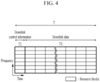
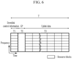
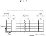
- FIGS. 4 , 5 , 6 , and 7 a subframe structure according to another exemplary embodiment of the present invention may be implemented as in FIGS. 4 , 5 , 6 , and 7 .
- a subframe may be implemented in four types.
- FIG. 4 shows the configuration of a first type of subframe according to another exemplary embodiment of the present invention.
- FIG. 5 shows the configuration of a second type of subframe according to another exemplary embodiment of the present invention.
- FIG. 6 shows the configuration of a third type of subframe according to another exemplary embodiment of the present invention.
- FIG. 7 shows the configuration of a fourth type of subframe according to another exemplary embodiment of the present invention.
- the flexible subframe of FIG. 1 may be variably selected from among first, second, third, and fourth types of subframes.
- the first time region T1 of the time domain T of the first type of subframe is allocated as a downlink control information (DC) region, and the second time region T2 is allocated as a downlink data (DD) region.
- DC downlink control information
- DD downlink data
- the first time region T1 of the time domain T of the second type of subframe is allocated as a downlink control information (DC) region
- the second time region T2 is allocated as a downlink data (DD) region
- the third time region T3 is allocated as a GP region
- the fourth time region T4 is allocated as an uplink control information (UC) region.
- DC downlink control information
- DD downlink data
- UC uplink control information
- DMRSs may be allocated first at the beginning of downlink data DD in the second time region T2, and then the downlink data DD may be allocated.
- the first time region T1 of the time domain T of the third type of subframe is allocated as a downlink control information (DC) region
- the second time region T2 is allocated as a GP region
- the third time region T3 is allocated as an uplink data (UD) region.
- DC downlink control information
- UD uplink data
- the first time region T1 of the time domain T of the fourth type of subframe is allocated as a downlink control information (DC) region
- the second time region T2 is allocated as a GP region
- the third time region T3 is allocated as an uplink data (UD) region
- the fourth time domain T4 is allocated as an uplink control information (UC) region.
- DC downlink control information
- UD uplink data
- UC uplink control information
- DMRSs may be allocated first at the beginning of uplink data UD in the second time region T2, and then the uplink data DD may be allocated.
- uplink control information may be additionally allocated to the uplink data (UD) region along with uplink data.
- uplink control information may be allocated to the uplink data (UD) region, and the uplink control information region T3 is provided separately.
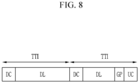
- a flexible subframe may be a combination of at least two types of subframes, among the first, second, third, and fourth types of subframes explained with reference to FIGS. 4 to 7 .
- FIG. 8 schematically shows the configuration of a downlink subframe according to still another exemplary embodiment of the present invention.
- FIG. 9 schematically shows the configuration of an uplink subframe according to a further exemplary embodiment of the present invention.
- the downlink (DL) subframe may include a structure in which the first type of subframe of FIG. 4 and the second type of subframe of FIG. 5 are consecutively arranged.
- the uplink (UL) subframe may include a structure in which the third type of subframe FIG. 6 and the fourth type of subframe of FIG. 7 are consecutively arranged.
- each type of subframe - that is, the first type of subframe, the second type of subframe, the third type of subframe, and the fourth type of subframe - may be given at TTls.
- FIG. 10 shows a series of processes in which a resource allocation apparatus using a time-division duplex communication scheme allocates resources for subframes.
- the resource allocation apparatus may be included in a terminal or a base station, or may be implemented as a separate piece of equipment on a network.
- the resource allocation apparatus allocates the time domain T of the downlink subframe as at least one downlink control information region, at least one downlink data region, and an uplink control information region (S103).
- a guard period GP is allocated between the downlink data region and the uplink control information region (S105).
- the step S105 applies to the subframes of FIG. 2 , FIG. 5 , and FIG. 8 .
- the resource allocation apparatus allocates the time domain T of the uplink subframe as at least one downlink control information region, at least one uplink data region, and an uplink control information region (S107).
- a guard period GP is allocated between the downlink control information region and the uplink data region (S109).
- the step S109 applies to the subframes of FIG. 3 , FIG. 6 , FIG. 7 , and FIG. 9 .
- FIG. 11 shows the configuration of a communication apparatus according to an exemplary embodiment of the present invention.
- the communication apparatus 100 includes a wireless communication unit 101, a memory 103, and a processor 105.
- the processor 105 may be configured to implement the procedures and/or methods proposed in the exemplary embodiments of the present invention.
- the memory 103 is connected to the processor 105 and stores various information relating to the operation of the processor 105.
- the wireless communication unit 101 is connected to the processor 105 and sends and/or receives wireless signals.
- the processor 105 may also be referred to as a controller, a microcontroller, a microprocessor, a microcomputer, or the like. Also, the processor 105 may be implemented by hardware, firmware, software, or a combination thereof.
- the processor 105 controls the wireless communication unit 101 to send and receive signals using uplink subframes or downlink subframes in accordance with the subframe structures explained with reference to FIGS. 2 to 9 .
- the wireless communication unit 101 sends an uplink subframe or receives a downlink subframe.
- the processor 105 processes the uplink subframe or downlink subframe in accordance with a predefined subframe structure stored in the memory 103.
- the processor 105 Upon receiving the downlink subframe, the processor 105 estimates the channel by receiving a demodulation reference signal DM-RS after receiving downlink control information. Then, the estimated information is used when demodulating downlink data which is to be received thereafter. Accordingly, channel estimation may be done first and then data is received, thereby making the data processing time faster, unlike in the conventional art where channel estimation is enabled only after all data is received because pilot information is included in downlink data.
- the processor 105 upon sending the uplink subframe, the processor 105 sends uplink data after sending a demodulation reference signal DM-RS.
- the processor 105 may mix uplink data and uplink control information up and send them in the same time region.
- the uplink control information may be sent in the time region allocated for uplink data. In this way, the uplink control information may be sent in the uplink data region which provides high output.
- the uplink control information may be sent in the uplink data region, and the uplink control information may be repeatedly sent in the uplink control information region.
- the above-explained exemplary embodiments of the present invention are not implemented only by a device and/or a method, but may be implemented through a program for realizing functions corresponding to the configurations of the exemplary embodiments of the present invention and a recording medium having the program recorded thereon.
Landscapes
- Engineering & Computer Science (AREA)
- Signal Processing (AREA)
- Computer Networks & Wireless Communication (AREA)
- Mobile Radio Communication Systems (AREA)
Applications Claiming Priority (4)
| Application Number | Priority Date | Filing Date | Title |
|---|---|---|---|
| KR20150101888 | 2015-07-17 | ||
| KR1020160077571A KR101922250B1 (ko) | 2015-07-17 | 2016-06-21 | 자원 할당 방법 및 통신 장치 |
| PCT/KR2016/006602 WO2017014435A1 (ko) | 2015-07-17 | 2016-06-22 | 자원 할당 방법 및 통신 장치 |
| EP16827939.6A EP3327954B1 (de) | 2015-07-17 | 2016-06-22 | Ressourcenzuteilungsverfahren und kommunikationsvorrichtung |
Related Parent Applications (2)
| Application Number | Title | Priority Date | Filing Date |
|---|---|---|---|
| EP16827939.6A Division EP3327954B1 (de) | 2015-07-17 | 2016-06-22 | Ressourcenzuteilungsverfahren und kommunikationsvorrichtung |
| EP16827939.6A Division-Into EP3327954B1 (de) | 2015-07-17 | 2016-06-22 | Ressourcenzuteilungsverfahren und kommunikationsvorrichtung |
Publications (2)
| Publication Number | Publication Date |
|---|---|
| EP4239943A2 true EP4239943A2 (de) | 2023-09-06 |
| EP4239943A3 EP4239943A3 (de) | 2023-10-25 |
Family
ID=57834103
Family Applications (1)
| Application Number | Title | Priority Date | Filing Date |
|---|---|---|---|
| EP23181836.0A Pending EP4239943A3 (de) | 2015-07-17 | 2016-06-22 | Ressourcenzuweisungsverfahren und kommunikationsvorrichtung |
Country Status (3)
| Country | Link |
|---|---|
| EP (1) | EP4239943A3 (de) |
| ES (1) | ES2959384T3 (de) |
| WO (1) | WO2017014435A1 (de) |
Families Citing this family (1)
| Publication number | Priority date | Publication date | Assignee | Title |
|---|---|---|---|---|
| US11722287B2 (en) * | 2015-09-02 | 2023-08-08 | Qualcomm Incorporated | Flexible time division duplexing subframe structure with latency reduction |
Family Cites Families (7)
| Publication number | Priority date | Publication date | Assignee | Title |
|---|---|---|---|---|
| US8559343B2 (en) * | 2009-12-23 | 2013-10-15 | Telefonaktiebolaget Lm Ericsson (Publ) | Flexible subframes |
| CN103563273B (zh) * | 2011-04-05 | 2017-06-09 | Lg电子株式会社 | 在无线通信系统中用于调度的方法和设备 |
| KR20140136923A (ko) * | 2012-03-22 | 2014-12-01 | 텔레포나크티에볼라게트 엘엠 에릭슨(피유비엘) | 무선 통신 시스템 내의 서브 프레임의 동적 구성 |
| US20130286902A1 (en) * | 2012-04-27 | 2013-10-31 | Qualcomm Incorporated | Flexible special subframe configuration for tdd in lte |
| JP6131458B2 (ja) * | 2012-06-27 | 2017-05-24 | シャープ株式会社 | 移動局装置、基地局装置、および無線通信方法 |
| CN111245561B (zh) * | 2013-01-18 | 2022-11-22 | 北京三星通信技术研究有限公司 | 一种处理灵活子帧的上下行传输的方法和设备 |
| WO2015014407A1 (en) * | 2013-08-02 | 2015-02-05 | Nokia Solutions And Networks Oy | Transmission mode arrangement for flexible time division duplexing (tdd) |
-
2016
- 2016-06-22 ES ES16827939T patent/ES2959384T3/es active Active
- 2016-06-22 EP EP23181836.0A patent/EP4239943A3/de active Pending
- 2016-06-22 WO PCT/KR2016/006602 patent/WO2017014435A1/ko not_active Ceased
Also Published As
| Publication number | Publication date |
|---|---|
| ES2959384T3 (es) | 2024-02-26 |
| WO2017014435A1 (ko) | 2017-01-26 |
| EP4239943A3 (de) | 2023-10-25 |
Similar Documents
| Publication | Publication Date | Title |
|---|---|---|
| EP3327954B1 (de) | Ressourcenzuteilungsverfahren und kommunikationsvorrichtung | |
| US11178649B2 (en) | Methods and systems for TDD PUCCH HARQ resource allocation for enhanced physical downlink control channel (ePDCCH) | |
| JP7418472B2 (ja) | マルチtrp pdsch送信方式の動的インジケーション | |
| US11902807B2 (en) | Method and apparatus for measuring and transmitting CR by user equipment in wireless communication system | |
| EP3540997B1 (de) | Verfahren zur übertragung eines uplink-signals in einem drahtloskommunikationssystem und vorrichtung dafür | |
| CN102355325B (zh) | 一种pucch资源映射的方法及装置 | |
| EP4007431A1 (de) | Flexible berechtigungsfreie ressourcenkonfigurationssignalisierung | |
| JP2020127242A (ja) | 無線通信システムにおける端末及び基地局の動作方法並びにそれをサポートする装置 | |
| EP3468084A1 (de) | Steuerkanal und datenkanalsende-/empfangsverfahren und vorrichtung für nr-system | |
| US8989079B2 (en) | Apparatus for transmitting and receiving uplink backhaul signal in wireless communication system and method thereof | |
| US20110310789A1 (en) | Method of uplink control channel allocation for a relay backhaul link | |
| CN106576355B (zh) | 上行数据发送装置、接收装置及方法 | |
| CN112436927A (zh) | 侧链路传送方法和装置 | |
| US10461909B2 (en) | Infrastructure equipment, communications device and methods | |
| EP2946507B1 (de) | Datenübertragung mit verwendung von vorkodierten referenzsymbolen von mehrfach-subframe | |
| US20250008549A1 (en) | Method and device for transmitting sidelink resource coordination information | |
| WO2012134115A2 (ko) | Tdd 기반 무선 통신 시스템에서 mbsfn 서브프레임을 이용한 통신 방법 및 장치 | |
| EP4239943A2 (de) | Ressourcenzuweisungsverfahren und kommunikationsvorrichtung | |
| KR20170055911A (ko) | 짧은 tti를 이용한 데이터 송수신 방법 및 장치 |
Legal Events
| Date | Code | Title | Description |
|---|---|---|---|
| PUAI | Public reference made under article 153(3) epc to a published international application that has entered the european phase |
Free format text: ORIGINAL CODE: 0009012 |
|
| STAA | Information on the status of an ep patent application or granted ep patent |
Free format text: STATUS: REQUEST FOR EXAMINATION WAS MADE |
|
| 17P | Request for examination filed |
Effective date: 20230627 |
|
| AC | Divisional application: reference to earlier application |
Ref document number: 3327954 Country of ref document: EP Kind code of ref document: P |
|
| AK | Designated contracting states |
Kind code of ref document: A2 Designated state(s): AL AT BE BG CH CY CZ DE DK EE ES FI FR GB GR HR HU IE IS IT LI LT LU LV MC MK MT NL NO PL PT RO RS SE SI SK SM TR |
|
| PUAL | Search report despatched |
Free format text: ORIGINAL CODE: 0009013 |
|
| AK | Designated contracting states |
Kind code of ref document: A3 Designated state(s): AL AT BE BG CH CY CZ DE DK EE ES FI FR GB GR HR HU IE IS IT LI LT LU LV MC MK MT NL NO PL PT RO RS SE SI SK SM TR |
|
| RIC1 | Information provided on ipc code assigned before grant |
Ipc: H04B 7/26 20060101ALI20230918BHEP Ipc: H04L 5/00 20060101ALI20230918BHEP Ipc: H04L 5/14 20060101AFI20230918BHEP |
|
| STAA | Information on the status of an ep patent application or granted ep patent |
Free format text: STATUS: EXAMINATION IS IN PROGRESS |
|
| 17Q | First examination report despatched |
Effective date: 20260223 |