EP4240068B1 - Procédé et appareil de communication sans fil - Google Patents
Procédé et appareil de communication sans fil Download PDFInfo
- Publication number
- EP4240068B1 EP4240068B1 EP23186688.0A EP23186688A EP4240068B1 EP 4240068 B1 EP4240068 B1 EP 4240068B1 EP 23186688 A EP23186688 A EP 23186688A EP 4240068 B1 EP4240068 B1 EP 4240068B1
- Authority
- EP
- European Patent Office
- Prior art keywords
- transmission power
- terminal
- physical sidelink
- sidelink channel
- path loss
- Prior art date
- Legal status (The legal status is an assumption and is not a legal conclusion. Google has not performed a legal analysis and makes no representation as to the accuracy of the status listed.)
- Active
Links
Images


Classifications
-
- H—ELECTRICITY
- H04—ELECTRIC COMMUNICATION TECHNIQUE
- H04W—WIRELESS COMMUNICATION NETWORKS
- H04W52/00—Power management, e.g. Transmission Power Control [TPC] or power classes
- H04W52/04—Transmission power control [TPC]
- H04W52/06—TPC algorithms
- H04W52/14—Separate analysis of uplink or downlink
-
- H—ELECTRICITY
- H04—ELECTRIC COMMUNICATION TECHNIQUE
- H04W—WIRELESS COMMUNICATION NETWORKS
- H04W52/00—Power management, e.g. Transmission Power Control [TPC] or power classes
- H04W52/04—Transmission power control [TPC]
- H04W52/18—TPC being performed according to specific parameters
- H04W52/24—TPC being performed according to specific parameters using SIR [Signal to Interference Ratio] or other wireless path parameters
- H04W52/246—TPC being performed according to specific parameters using SIR [Signal to Interference Ratio] or other wireless path parameters where the output power of a terminal is based on a path parameter calculated in said terminal
-
- H—ELECTRICITY
- H04—ELECTRIC COMMUNICATION TECHNIQUE
- H04W—WIRELESS COMMUNICATION NETWORKS
- H04W52/00—Power management, e.g. Transmission Power Control [TPC] or power classes
- H04W52/04—Transmission power control [TPC]
- H04W52/18—TPC being performed according to specific parameters
- H04W52/24—TPC being performed according to specific parameters using SIR [Signal to Interference Ratio] or other wireless path parameters
-
- H—ELECTRICITY
- H04—ELECTRIC COMMUNICATION TECHNIQUE
- H04W—WIRELESS COMMUNICATION NETWORKS
- H04W4/00—Services specially adapted for wireless communication networks; Facilities therefor
- H04W4/30—Services specially adapted for particular environments, situations or purposes
- H04W4/40—Services specially adapted for particular environments, situations or purposes for vehicles, e.g. vehicle-to-pedestrians [V2P]
-
- H—ELECTRICITY
- H04—ELECTRIC COMMUNICATION TECHNIQUE
- H04W—WIRELESS COMMUNICATION NETWORKS
- H04W52/00—Power management, e.g. Transmission Power Control [TPC] or power classes
- H04W52/04—Transmission power control [TPC]
- H04W52/06—TPC algorithms
- H04W52/12—Outer and inner loops
-
- H—ELECTRICITY
- H04—ELECTRIC COMMUNICATION TECHNIQUE
- H04W—WIRELESS COMMUNICATION NETWORKS
- H04W52/00—Power management, e.g. Transmission Power Control [TPC] or power classes
- H04W52/04—Transmission power control [TPC]
- H04W52/18—TPC being performed according to specific parameters
- H04W52/24—TPC being performed according to specific parameters using SIR [Signal to Interference Ratio] or other wireless path parameters
- H04W52/242—TPC being performed according to specific parameters using SIR [Signal to Interference Ratio] or other wireless path parameters taking into account path loss
-
- H—ELECTRICITY
- H04—ELECTRIC COMMUNICATION TECHNIQUE
- H04W—WIRELESS COMMUNICATION NETWORKS
- H04W52/00—Power management, e.g. Transmission Power Control [TPC] or power classes
- H04W52/04—Transmission power control [TPC]
- H04W52/18—TPC being performed according to specific parameters
- H04W52/28—TPC being performed according to specific parameters using user profile, e.g. mobile speed, priority or network state, e.g. standby, idle or non-transmission
- H04W52/281—TPC being performed according to specific parameters using user profile, e.g. mobile speed, priority or network state, e.g. standby, idle or non-transmission taking into account user or data type priority
-
- H—ELECTRICITY
- H04—ELECTRIC COMMUNICATION TECHNIQUE
- H04W—WIRELESS COMMUNICATION NETWORKS
- H04W52/00—Power management, e.g. Transmission Power Control [TPC] or power classes
- H04W52/04—Transmission power control [TPC]
- H04W52/30—Transmission power control [TPC] using constraints in the total amount of available transmission power
- H04W52/36—Transmission power control [TPC] using constraints in the total amount of available transmission power with a discrete range or set of values, e.g. step size, ramping or offsets
- H04W52/367—Power values between minimum and maximum limits, e.g. dynamic range
-
- H—ELECTRICITY
- H04—ELECTRIC COMMUNICATION TECHNIQUE
- H04W—WIRELESS COMMUNICATION NETWORKS
- H04W52/00—Power management, e.g. Transmission Power Control [TPC] or power classes
- H04W52/04—Transmission power control [TPC]
- H04W52/38—TPC being performed in particular situations
- H04W52/383—TPC being performed in particular situations power control in peer-to-peer links
-
- H—ELECTRICITY
- H04—ELECTRIC COMMUNICATION TECHNIQUE
- H04W—WIRELESS COMMUNICATION NETWORKS
- H04W72/00—Local resource management
- H04W72/12—Wireless traffic scheduling
- H04W72/1263—Mapping of traffic onto schedule, e.g. scheduled allocation or multiplexing of flows
-
- H—ELECTRICITY
- H04—ELECTRIC COMMUNICATION TECHNIQUE
- H04W—WIRELESS COMMUNICATION NETWORKS
- H04W72/00—Local resource management
- H04W72/50—Allocation or scheduling criteria for wireless resources
- H04W72/56—Allocation or scheduling criteria for wireless resources based on priority criteria
- H04W72/566—Allocation or scheduling criteria for wireless resources based on priority criteria of the information or information source or recipient
- H04W72/569—Allocation or scheduling criteria for wireless resources based on priority criteria of the information or information source or recipient of the traffic information
-
- H—ELECTRICITY
- H04—ELECTRIC COMMUNICATION TECHNIQUE
- H04W—WIRELESS COMMUNICATION NETWORKS
- H04W92/00—Interfaces specially adapted for wireless communication networks
- H04W92/16—Interfaces between hierarchically similar devices
- H04W92/18—Interfaces between hierarchically similar devices between terminal devices
-
- H—ELECTRICITY
- H04—ELECTRIC COMMUNICATION TECHNIQUE
- H04W—WIRELESS COMMUNICATION NETWORKS
- H04W52/00—Power management, e.g. Transmission Power Control [TPC] or power classes
- H04W52/04—Transmission power control [TPC]
- H04W52/18—TPC being performed according to specific parameters
- H04W52/22—TPC being performed according to specific parameters taking into account previous information or commands
- H04W52/226—TPC being performed according to specific parameters taking into account previous information or commands using past references to control power, e.g. look-up-table
-
- H—ELECTRICITY
- H04—ELECTRIC COMMUNICATION TECHNIQUE
- H04W—WIRELESS COMMUNICATION NETWORKS
- H04W52/00—Power management, e.g. Transmission Power Control [TPC] or power classes
- H04W52/04—Transmission power control [TPC]
- H04W52/18—TPC being performed according to specific parameters
- H04W52/24—TPC being performed according to specific parameters using SIR [Signal to Interference Ratio] or other wireless path parameters
- H04W52/247—TPC being performed according to specific parameters using SIR [Signal to Interference Ratio] or other wireless path parameters where the output power of a terminal is based on a path parameter sent by another terminal
-
- H—ELECTRICITY
- H04—ELECTRIC COMMUNICATION TECHNIQUE
- H04W—WIRELESS COMMUNICATION NETWORKS
- H04W52/00—Power management, e.g. Transmission Power Control [TPC] or power classes
- H04W52/04—Transmission power control [TPC]
- H04W52/30—Transmission power control [TPC] using constraints in the total amount of available transmission power
- H04W52/34—TPC management, i.e. sharing limited amount of power among users or channels or data types, e.g. cell loading
- H04W52/346—TPC management, i.e. sharing limited amount of power among users or channels or data types, e.g. cell loading distributing total power among users or channels
Definitions
- Embodiments of the present application relate to the field of communication technologies, and in particular to a method and apparatus for wireless communication.
- LTE-V2X Long Term Evolution Vehicle to Everything
- LTE-V2X Internet of Vehicles system based on sidelink transmission technology, and different from the traditional Long Term Evolution (LTE) data transmission method, it can employ terminal-to-terminal direct communication, and thus has higher spectrum efficiency and lower transmission delay.
- an uplink frequency band of a Frequency Division Duplex (FDD) system or an uplink subframe of a Time Division Duplex (TDD) system can be used for sidelink transmission, and accordingly, if one terminal performs sidelink transmission while another terminal performs uplink transmission at the same time, there will be mutual interference between the sidelink transmission and the uplink transmission.
- FDD Frequency Division Duplex
- TDD Time Division Duplex
- an open-loop power control scheme is introduced, and a network device instructs the terminal to determine a transmission power for the sidelink transmission based on a path loss between the terminal and the network.
- the New Radio Vehicle to Everything (NR-V2X) based system needs to support autonomous driving, and puts forward higher requirements for data interaction between vehicles, such as higher reliability requirements, and in this case, how to perform power control to meet the transmission demand is a problem that needs to be solved urgently.
- NR-V2X New Radio Vehicle to Everything
- the communication system on which the IoV system is based can be a Global System of Mobile communication (GSM) system, a Code Division Multiple Access (CDMA) system, a Wideband Code Division Multiple Access (WCDMA) system, a General Packet Radio Service (GPRS), a LTE system, a LTE Frequency Division Duplex (FDD) system, a LTE Time Division Duplex (TDD) system, a Universal Mobile Telecommunication System (UMTS), a Worldwide Interoperability for Microwave Access (WiMAX) communication system and a 5G new radio (NR) system, among others.
- GSM Global System of Mobile communication
- CDMA Code Division Multiple Access
- WCDMA Wideband Code Division Multiple Access
- GPRS General Packet Radio Service
- LTE system LTE Frequency Division Duplex
- FDD Frequency Division Duplex
- TDD Time Division Duplex
- UMTS Universal Mobile Telecommunication System
- WiMAX Worldwide Interoperability for Microwave Access
- NR 5G new radio
- the terminal device in the embodiments of the present application can be a terminal device capable of implementing D2D communication.
- it may be a vehicle-mounted terminal device, a terminal device in a 5G network, a terminal device in a future evolution Public Land Mobile Network (PLMN) or the like, which is not limited in the embodiments of the present application.
- PLMN Public Land Mobile Network
- FIG. 1 is schematic diagram of an application scenario of an embodiment of the present application.
- FIG. 1 exemplarily shows one network device and two terminal devices.
- the wireless communication system in an embodiment of the present application can include a plurality of network devices, and other numbers of terminal devices can be included in the coverage of each network device, which is not limited in the embodiments of the present application.
- the terminal device can use mode 3 and mode 4 to perform communication.
- the terminal devices 121 and 122 may communicate in a D2D communication mode.
- the terminal devices 121 and 122 directly communicate through a D2D link, that is, a SideLink (SL).
- SL SideLink
- transmission resources of the terminal device are assigned by the base station, and the terminal device can send data on the SL according to the resources assigned by the base station.
- the base station can assign resources for a single transmission for the terminal device, or can assign semi-persistent transmission resources for the terminal.
- the terminal device adopts a transmission mode of sensing plus reservation, and the terminal device autonomously selects transmission resources on the SL resources. Specifically, the terminal device obtains a set of available transmission resources from a resource pool by means of sensing, and randomly selects a resource from the set of available transmission resources for data transmission.
- mode 3 and mode 4 are merely illustrative of the two transmission modes, and other transmission modes may be defined.
- mode 1 and mode 2 are introduced in NR-V2X.
- Mode 1 represents that the sidelink transmission resources of the terminal device are assigned by the base station
- mode 2 represents that the sidelink transmission resources of the terminal device are selected by the terminal.
- system and “network” are often used interchangeably herein.
- the term “and/or” used herein is merely to describe relative relationships of relative objects, indicating that there can be three kinds of relationships. For example, A and/or B can indicate three cases where A exists alone, A and B exist simultaneously, or B exists alone.
- the character “/” used herein generally indicates that the related objects before and after this character are in an "or” relationship.
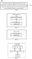
- FIG. 2 is a schematic flowchart of a wireless communication method according to an embodiment of the present application.
- the method can be performed by a terminal device in the Internet of Vehicles system, such as the terminal device 121 or the terminal device 122.
- the method 200 include:
- the first physical sidelink channel may be a sidelink channel used for communication between the terminals, such as a Physical Sidelink Broadcast Channel (PSBCH), a Physical Sidelink Feedback Channel (PSFCH), a Physical Sidelink Shared Channel (PSSCH), a Physical Sidelink Control Channel (PSCCH) or the like.
- PSBCH Physical Sidelink Broadcast Channel
- PSFCH Physical Sidelink Feedback Channel
- PSSCH Physical Sidelink Shared Channel
- PSCCH Physical Sidelink Control Channel
- the first criterion is used for indicating a manner of determining the transmission power for the sidelink channel that is used for communication between the terminals.
- the first criterion may indicate that the transmission power is determined according to a path loss, or that the transmission power is determined according to attributes of sidelink data to be transmitted (for example, a priority, reliability, etc.), or the transmission power is determined according to the interference on the uplink transmission by the sidelink transmission, etc.
- the first terminal may determine a maximum transmission power of the first terminal as the target transmission power for the first physical sidelink channel. It should be understood that the maximum transmission power of the first terminal here may be pre-configured, for example, 23dBm.
- the first terminal may determine the target transmission power for the first physical sidelink channel according to first configuration information.
- the first configuration information may include a first mapping relationship, and for example, the first mapping relationship may be a mapping relationship between a maximum transmission power and at least one of priority information or a Channel Busy Ratio (CBR), so that the first terminal can determine the maximum transmission power according to the priority information of the sidelink data to be transmitted and/or the CBR of the current channel in combination with the first mapping relationship, where the maximum transmission power here is a maximum transmission power determined based on the first configuration information. Further, the first terminal may determine the target transmission power for transmitting the first physical sidelink channel according to the maximum transmission power determined based on the first configuration information. For example, the maximum transmission power may be determined as the target transmission power for transmitting the first physical sidelink channel.
- CBR Channel Busy Ratio
- the priority of the sidelink data to be transmitted is 1, when the CBR of the current channel is 0.8, the maximum transmission power can be determined to be 18 dBm from Table 1, and the target transmission power for the first physical sidelink channel can be further determined to be 18 dBm.
- the first mapping relationship may also be a mapping relationship between other attributes of the data to be transmitted and the maximum transmission power.
- the first mapping relationship may be a mapping relationship between the attributes such as Quality of Service (QoS), reliability or delay, the CBR, and the maximum transmission power, and the embodiments of the present application are not limited thereto.
- the first terminal may determine the first transmission power according to the first path loss between the first terminal and the network device. Further, the first terminal may determine the target transmission power for the first physical sidelink channel according to the first transmission power.
- the first transmission power is determined according to the first path loss and in consideration of limitation of the maximum transmission power of the first terminal, for example, the minimum of the transmission power determined according to the first path loss and the maximum transmission power of the first terminal can be determined as the first transmission power, and in this case, the first terminal may directly determine the first transmission power as the target transmission power for the first physical sidelink channel.
- the sixth configuration information may also be other configuration information, which is not limited in the embodiments of the present application.
- the first criterion indicates using the manner 7 to determine the transmission power for the physical sidelink channel.
- the first criterion may indicate determining the transmission power for the physical sidelink channel with the minimum of the first transmission power and the second transmission power, so as to reduce the interference on the uplink channel by the sidelink channel.
- the seventh configuration information may also be other configuration information, which is not limited in the embodiments of the present application.
- the seventh configuration information may be configured by the network, or may be pre-configured, or may be configured by the group head terminal.
- the first criterion can indicates using the manner 8 to determine the transmission power for the physical sidelink channel.
- the first criterion may indicate using the maximum of the first transmission power and the second transmission power to determine the transmission power, so as to ensure the reliability and delay requirements of the sidelink channel transmission.
- the first terminal can determine the target transmission power according to a first threshold and a first attribute of the sidelink data to be transmitted.
- the first threshold may be pre-configured, or configured by the network, or configured by the group head terminal.
- the first attribute may include at least one of the following: a priority, reliability, delay, a transmission rate, a throughput, a transmission distance or communication distance, QoS, a 5G QoS Indicator (5QI), or a V2X QoS Indicator (VQI).
- a priority a priority, reliability, delay, a transmission rate, a throughput, a transmission distance or communication distance, QoS, a 5G QoS Indicator (5QI), or a V2X QoS Indicator (VQI).
- the first threshold may be at least one of the following: a priority threshold, a reliability threshold, a delay threshold, a transmission rate threshold, a throughput threshold, a transmission distance threshold, a 5QI threshold or a VQI threshold.
- the first threshold is the priority threshold. If the priority of the sidelink data to be transmitted is less than or equal to the first threshold, that is, the priority of the sidelink data to be transmitted is high, the first terminal may determine the target transmission power according to the second path loss, and transmit the first physical sidelink channel with the target transmission power; or if the value of the priority of the sidelink data to be transmitted is greater than the first threshold, the priority of the sidelink data to be transmitted is low, and the first terminal may determine the target transmission power according to the first path loss, and transmit the first physical sidelink channel with the target transmission power. In this way, on the one hand, reliable transmission of the sidelink data with high priority can be ensured, and on the other hand, the interference on uplink transmission by the sidelink transmission with low priority can be reduced.
- the first attribute is the reliability
- the first threshold is the reliability threshold. If the reliability requirement of the sidelink data to be transmitted is less than, or less than or equal to the first threshold (for example, 90% or 95%), the first terminal may determine the target transmission power according to the first path loss, and transmit the first physical sidelink channel with the target transmission power; or if the reliability requirement of the sidelink data to be transmitted is higher than the first threshold, the first terminal may determine the target transmission power according to the second path loss, and transmit the first physical sidelink channel with the target transmission power. In this way, on the one hand, reliable transmission of the sidelink data with high reliability requirements can be ensured, and on the other hand, the interference on the uplink transmission by the sidelink transmission with low reliability requirements can be reduced.
- the first terminal may determine the target transmission power according to the first threshold and the first attribute of the sidelink data to be transmitted, or the first terminal may determine the target transmission power according to the first threshold, the first attribute of the sidelink data to be transmitted and the maximum transmission power of the first terminal.
- the first terminal may determine the target transmission power according to a type of the first physical sidelink channel.
- the first terminal may determine to determine the target transmission power according to the second path loss, and transmit the first physical sidelink channel with the target transmission power.
- the reliability or importance of the PSBCH, PSCCH and PSFCH are higher, by transmitting such type of sidelink channels with the transmission power determined according to the second path loss, it is beneficial to ensure the reliability and delay requirements of the transmission of such type of sidelink channels.
- the target transmission power of the first terminal cannot exceed the maximum transmission power of the first terminal. That is, the target transmission power calculated according to the above implementations should be limited by the maximum transmission power of the first terminal.
- the first terminal may also transmit multiple sidelink channels at the same time (case 1).
- the first terminal can also transmit a third physical sidelink channel to another terminal, such as a fourth terminal, or transmits a fourth physical sidelink channel to a fifth terminal.
- the terminal device may also send an uplink channel to the network device while transmitting the sidelink channel (case 2), which is not limited in the embodiments of the present application.
- the first terminal may also determine the target transmission power for transmitting the third physical sidelink channel or the fourth physical sidelink channel according to the methods described in the foregoing manner 1 to manner 10, which will not be described in detail here.
- the first terminal may determine the transmission power for the first physical sidelink channel according to the attribute of the sidelink data to be transmitted.
- the attribute of the sidelink data here, reference can be made to the first attribute mentioned above, which will not be repeated here.
- the first terminal may determine to transmit only the first physical sidelink channel, for example, transmit the first physical sidelink channel with the maximum transmission power of the first terminal, or to transmit the first physical sidelink channel with the second transmission power as described above; or the first terminal may also determine to first guarantee the transmission power for the first physical sidelink channel, and transmit the uplink channel with remaining power when there is the remaining power in the transmission power of the first terminal. For example, the first terminal transmits the first physical sidelink channel with the second transmission power, and if the second transmission power is less than the maximum transmission power of the first terminal, the remaining power is used as the transmission power for the uplink channel.
- the method 200 further includes: the first terminal determines a target transmission power for a second physical sidelink channel according to the target transmission power for the first physical sidelink channel and a second criterion.
- the first physical sidelink channel is a PSSCH
- the second physical sidelink channel is a PSCCH or PSFCH
- the first physical sidelink channel is a PSBCH
- the second physical sidelink channel is the PSCCH or PSSCH.
- the second criterion includes at least one of the following:
- A may be pre-configured, or may be configured by a network device, or may be configured by a group head terminal.
- the first terminal may determine the power spectrum density for the first physical sidelink channel as the power spectrum density for the second physical sidelink channel, and then determine the transmission power for the second physical sidelink channel according to the power spectrum density for the second physical sidelink channel and a frequency domain resource size of the second physical sidelink channel. Specifically, the transmission power for the second physical sidelink channel may be determined according to the frequency domain resources occupied by the second physical sidelink channel and the power spectral density for the first physical sidelink channel.
- the first ratio C may be pre-configured, or may be configured by the network device, or may be configured by the group head terminal.
- the transmission power for the PSSCH can be determined according to the first criterion in the above embodiments, and this transmission power can be regarded as the transmission power for the PSSCH that does not overlap the PSCCH in the time domain. Further, the transmission power for the PSCCH is determined according to the second criterion.
- the transmission power for the PSCCH can be determined according to the frequency domain resources occupied by the PSCCH and the power spectrum density of the PSSCH, and the transmission power for the PSSCH that overlaps the PSCCH in the time domain is determined according to the power spectrum density of the PSSCH and the frequency domain resources of the PSSCH that overlaps the PSCCH in the time domain.
- the resources occupied by the first physical sidelink channel and the second physical sidelink channel may overlap, or may not overlap, which is not specifically limited in the embodiments of the present application.
- the first terminal can determine the transmission power for the physical sidelink channel according to the first criterion that is pre-configured or is configured by the network device.
- the first terminal can be configured to determine the transmission power according to the first path loss or the second path loss, so that the interference on the uplink channel by the sidelink channel can be controlled.
- the first terminal can determine the transmission power for the physical sidelink channel according to the first criterion by itself. For example, the first terminal can determine the transmission power according to the attributes of the data to be transmitted, the first path loss, the second path loss, etc., which is beneficial to guarantee the characteristics such as the reliability and low latency of the sidelink data transmission.
- the first terminal may determine the transmission power for the physical sidelink channel according to the first criterion configured by the group head terminal.
- the group head terminal can control the transmission power of the terminals in the group, thereby ensuring the characteristics such as the reliability and low delay of the communication between the terminals in the group, and such power control method can be applied to scenarios with high delay and reliability requirements such as vehicle formations.
- the wireless communication method according to the embodiments of the present application is described in detail from the perspective of the first terminal in connection with FIGS. 2 and 3 .
- the following describes in detail a wireless communication method according to another embodiment of the present application from the perspective of a network device or a group head terminal with reference to FIG. 4 . It should be understood that the description on the network device or the group head terminal side corresponds to the description on the first terminal side, and reference can be made to similar descriptions above, which will not be repeated here.
- FIG. 4 is a schematic flowchart of a wireless communication method 300 according to another embodiment of the present application.
- the method 300 may be performed by the network device in the communication system shown in FIG. 1 .
- the method 300 includes the following content.
- the first device is a network device or a group head terminal of a communication group in which the first terminal is located.
- the first criterion may be configured by the network device or the group head terminal, or the first criterion may also be pre-configured.
- the first criterion is used for indicating at least one of the following:
- the first configuration information includes a first mapping relationship
- the first mapping relationship is a mapping relationship between a maximum transmission power and at least one of priority information or a channel busy ratio (CBR).
- CBR channel busy ratio
- the first attribute includes at least one of the following: a priority, reliability, a throughput, a transmission rate, a transmission distance, or a communication distance; and the first threshold is at least one of the following: a priority threshold, a reliability threshold, a throughput threshold, a transmission rate threshold, a transmission distance threshold, or a communication distance threshold.
- the first device determining the first criterion indicated by the first indication information according to the first attribute includes:
- the method further includes: the first device sending a second criterion to the first terminal, where the second criterion is used for the first terminal to determine the target transmission power for transmitting a second physical sidelink channel to the second terminal.
- FIG. 5 is a schematic block diagram of a terminal device 400 according to an embodiment of the present application. As shown in FIG. 5 , the device 400 includes:
- the first criterion is used for indicating at least one of the following:
- the first criterion is pre-configured
- the first configuration information includes a first mapping relationship
- the first mapping relationship is a mapping relationship between a maximum transmission power and at least one of priority information or a channel busy ratio (CBR).
- CBR channel busy ratio
- the determining module 410 is specifically configured to: determine a maximum transmission power according to a priority of the sidelink data to be transmitted and/or a CBR of the current channel in combination with the first mapping relationship; and determine the maximum transmission power as the target transmission power for the first physical sidelink channel.
- the maximum transmission power here is the maximum transmission power determined according to the first configuration information.
- the determining module 410 is further configured to: determine, by the first terminal, the target transmission power for the first physical sidelink channel according to a minimum of the following: a maximum transmission power; and a minimum of the first transmission power and the second transmission power, where the maximum transmission power includes a maximum transmission power determined according to the first configuration information, and/or the maximum transmission power of the first terminal.
- the determining module 410 is further configured to: determine, by the first terminal, the target transmission power for the first physical sidelink channel according to a minimum of the following: a maximum transmission power; and a maximum of the first transmission power and the second transmission power, where the maximum transmission power includes a maximum transmission power determined according to the first configuration information, and/or the maximum transmission power of the first terminal.
- the determining module 410 is further configured to: determine the target transmission power for the first physical sidelink channel from the first transmission power and the second transmission power according to a first attribute of the sidelink data to be transmitted on the first physical sidelink channel and a first threshold.
- the determining module 410 is further configured to:
- the device further includes: the communication module 420 configured to transmit second indication information to a network device or a third terminal, where the second indication information is used for indicating the first attribute of the sidelink data to be transmitted, and the third terminal is a group head terminal of a communication group in which the device is located.
- the determining module 410 is further configured to:
- the determining module 410 is further configured to: determine a target transmission power for a second physical sidelink channel according to the target transmission power for the first physical sidelink channel and a second criterion.
- the second criterion includes at least one of the following:
- the second criterion is pre-configured
- the device 400 can correspond to the first terminal in the method embodiments of the present application, and the above-mentioned and other operations and/or functions of the units in the device 400 are used to implement the process for the first terminal in method 200 as shown in FIG. 2 , which will not be repeated here for the sake of brevity.
- FIG. 6 is a schematic block diagram of a wireless communication device according to an embodiment of the present application.
- the device 500 of FIG. 6 includes: a communication module 510 configured to send first indication information to a first terminal, where the first indication information is used for indicating a first criterion, and the first criterion is used for the first terminal to determine a transmission power for transmitting a first physical sidelink channel to a second terminal.
- the first criterion is used for indicating at least one of the following:
- the determining module is specifically configured to:
- the communication module 510 is further configured to: send a second criterion to the first terminal, where the second criterion is used for the first terminal to determine a target transmission power for transmitting a second physical sidelink channel to the second terminal.
- the second criterion includes at least one of the following:
- the device is a network device or a group head terminal of a communication group in which the first terminal is located.
- the device 500 according to the embodiment of the present application can correspond to the first device in the method embodiments of the present application, and the above-mentioned and other operations and/or functions of the units in the device 500 are used to implement the corresponding process of the first device in the method 300 of FIG. 4 , which will not be repeated here for the sake of brevity.
- FIG. 7 is a schematic structural diagram of a communication device 600 according to an embodiment of the present application.
- the communication device 600 shown in FIG. 7 includes a processor 610.
- the processor 610 can call and execute a computer program from a memory to carry out the methods in the embodiments of the present application.
- the communication device 600 can further include a memory 620.
- the processor 610 can call and run the computer program from the memory 620 to carry out the methods in the embodiments of the present application.
- the communication device 600 can further include a transceiver 630, and the processor 610 can control the transceiver 630 to communicate with other devices, and specifically, to transmit information or data to other devices, or to receive information or data transmitted from other devices.
- the transceiver 630 can include a transmitter and a receiver.
- the transceiver 630 can further include an antenna, and the number of the antennas can be one or more.
- the communication device 600 can specifically be the network device or the group head terminal in the embodiments of the present application, and the communication device 600 can carry out the corresponding processes which are implemented by the network device or the group head terminal in the methods of the embodiments of the present application, which will not be repeated here for the sake of brevity.
- the communication device 600 can specifically be the first terminal in the embodiments of the present application, and the communication device 600 can implement the corresponding process that is implemented by the first terminal in the methods according to the embodiments of the present application, which will not be repeated here for the sake of brevity.
- FIG. 8 is a schematic structural diagram of a chip in an embodiment of the present application.
- the chip 700 shown in FIG. 8 includes a processor 710 which can call and run a computer program from a memory to implement the methods in the embodiments of the present application.
- the chip 700 can further include a memory 720.
- the processor 710 can call and run the computer program from the memory 720 to implement the methods in the embodiments of the present application.
- the memory 720 can be a separate device independent of the processor 710, or can be integrated in the processor 710.
- the chip 700 can further include an input interface 730.
- the processor 710 can control the input interface 730 to communicate with other devices or chips, and specifically, to obtain information or data transmitted by other devices or chips.
- the chip 700 can further include an output interface 740.
- the processor 710 can control the output interface 740 to communicate with other devices or chips, and specifically, to output information or data to other devices or chips.
- the chip can be applied to the first terminal in the embodiments of the present application, and the chip can implement the corresponding process which is implemented by the first terminal in the methods according to the embodiments of the present application, which will not be repeated here for the sake of brevity.
- the chip can be applied to the network device or the group head terminal in the embodiments of the present application, and the chip can carry out the corresponding processes which are implemented by the network device or the group head terminal in the methods of the embodiments of the present application, which will not be repeated here for the sake of brevity.
- the chip mentioned in the embodiments of the present application can also be referred to as a system-level chip, a system chip, a chip system, or a system-on-chip.
- FIG. 9 is a schematic block diagram of a communication system 900 provided by an embodiment of the present application. As shown in FIG. 9 , the communication system 900 includes a first communication device 910 and a second communication device 920.
- the steps of the methods disclosed in connection with the embodiments of the present disclosure can be directly embodied in and performed by a hardware decoding processor, or can be implemented by a combination of hardware and software modules in the decoding processor.
- the software modules can be located in a mature storage medium in the art such as a random access memory, a flash memory, a read-only memory, a programmable read-only memory, an electrically erasable programmable memory or a register.
- the storage medium is located in the memory, and the processor reads information in the memory and implements the steps of the above methods in combination with the hardware thereof.
- the memory in the embodiments of the present disclosure can also be a Static RAM (SRAM), a Dynamic RAM (DRAM), a Synchronous DRAM (SDRAM), a Double Data Rate SDRAM (DDR SDRAM), an Enhanced SDRAM (ESDRAM), a Synch-Link DRAM (SLDRAM), a Direct Rambus RAM (DR RAM), among others. That is to say, the memory in the embodiments of the present disclosure is intended to include but is not limited to those and any other suitable types of memories.
- SRAM Static RAM
- DRAM Dynamic RAM
- SDRAM Synchronous DRAM
- DDR SDRAM Double Data Rate SDRAM
- ESDRAM Enhanced SDRAM
- SLDRAM Synch-Link DRAM
- DR RAM Direct Rambus RAM
- the embodiments of the present application also provide a computer-readable storage medium for storing a computer program.
- the computer-readable storage medium can be applied to the network device in the embodiments of the present application, and the computer program causes a computer to perform the corresponding processes which are implemented by the network device in the methods of the embodiments of the present application, which will not be repeated here for the sake of brevity.
- the computer-readable storage medium can be applied to the mobile terminal/terminal device in the embodiments of the present application, and the computer program causes a computer to perform the corresponding processes which are implemented by the mobile terminal/terminal device in the methods of the embodiments of the present application, which will not be repeated here for the sake of brevity.
- the embodiments of the present application also provide a computer program product including computer program instructions.
- the computer program product can be applied to the network device in the embodiments of the present application, and the computer program instructions cause a computer to perform the corresponding processes implemented by the network device in the methods according to the embodiments of the present application, which will not be repeated here for the sake of brevity.
- the computer program product can be applied to the mobile terminal/terminal device in the embodiments of the present application, and the computer program instructions cause a computer to perform the corresponding processes which are implemented by the mobile terminal/terminal device in the methods of the embodiments of the present application, which will not be repeated here for the sake of brevity.
- the embodiments of the application also provide a computer program.
- the computer program can be applied to the network device in the embodiments of the present application, and when running on a computer, the computer program causes the computer to perform the corresponding process implemented by the network device in the methods according to the embodiments of the present application, which will not be repeated here for the sake of brevity.
- the computer program can be applied to the mobile terminal/terminal device in the embodiments of the present application, and when running on a computer, the computer program causes the computer to perform the corresponding processes implemented by the mobile terminal/terminal device in the methods of the embodiments of the present application, which will not be repeated here for the sake of brevity.
- the systems, devices, and methods disclosed in several embodiments of the present disclosure can be implemented in other manners.
- the device embodiments described above are merely illustrative.
- the division of the units is only a logical function division, and in actual implementations, there can be other division manners.
- a plurality of units or components can be combined or integrated into another system, or some features can be ignored or not implemented.
- the coupling or direct coupling or communication connection shown or discussed herein can also be indirect coupling or communication connection through some interfaces, devices or units, and can be in electrical, mechanical or other forms.
- the units described as separate components may be or may not be physically separated, and the components shown as units may be or may not be physical units, that is, they may be located in one place or may be distributed on multiple network units. Some or all of the units can be selected to achieve the objectives of the solutions of the embodiments according to actual requirements.
- the functional units in the embodiments of the present disclosure can be integrated into one processing unit, or each unit can individually exist physically, or two or more of the units can be integrated into one unit.
Landscapes
- Engineering & Computer Science (AREA)
- Computer Networks & Wireless Communication (AREA)
- Signal Processing (AREA)
- Mobile Radio Communication Systems (AREA)
- Communication Control (AREA)
Claims (12)
- Procédé de communication sans fil, comprenant :la détermination (S210), par un premier terminal, d'une puissance d'émission d'un premier canal physique de liaison latérale selon un premier critère, le premier critère étant utilisé pour indiquer un mode de détermination d'une puissance d'émission d'un canal de liaison latérale utilisé pour la communication entre des terminaux ; etl'émission (S220), par le premier terminal, du premier canal physique de liaison latérale vers un second terminal avec la puissance d'émission du premier canal physique de liaison latérale,dans lequel la détermination, par le premier terminal, de la puissance d'émission du premier canal physique de liaison latérale selon le premier critère comprend :la détermination de la puissance d'émission du premier canal physique de liaison latérale en fonction d'une première puissance d'émission maximale, d'une seconde puissance d'émission maximale, d'une première puissance d'émission et d'une seconde puissance d'émission, dans lequel la première puissance d'émission maximale est une puissance d'émission maximale du premier terminal, la seconde puissance d'émission maximale est déterminée en fonction de premières informations de configuration, les premières informations de configuration comprennent une première relation de mappage, et la première relation de mappage est une relation de mappage entre une puissance d'émission maximale et au moins un d'informations de priorité ou d'un taux d'occupation de canal, CBR, la première puissance d'émission est déterminée en fonction d'un premier affaiblissement de propagation, l'affaiblissement de propagation est un affaiblissement de propagation entre le premier terminal et un dispositif de réseau, la seconde puissance d'émission est déterminée en fonction d'un second affaiblissement de propagation, et le second affaiblissement de propagation trajet est un affaiblissement de propagation entre le premier terminal et le second terminal,dans lequel la puissance d'émission du premier canal physique de liaison latérale satisfait la formule suivante :
 dans lequel P est la puissance d'émission du premier canal physique de liaison latérale, P1 est la première puissance d'émission, P2 est la seconde puissance d'émission, Pcmax est la première puissance d'émission maximale et Pmax-CBR est la seconde puissance d'émission maximale.
 - Procédé selon la revendication 1, dans lequel la première puissance d'émission maximale est préconfigurée.
- Procédé selon la revendication 1, dans lequel le second affaiblissement de propagation est déterminé par le premier terminal en fonction d'une puissance de réception de signal de référence de liaison latérale, S-RSRP, envoyée par le second terminal.
- Procédé selon la revendication 1, comprenant en outre :
la détermination, par le premier terminal, d'une puissance d'émission d'un second canal physique de liaison latérale en fonction de la puissance d'émission du premier canal physique de liaison latérale et d'un second critère, dans lequel le deuxième critère est utilisé pour indiquer une relation entre la puissance d'émission du premier canal physique de liaison latérale et la puissance d'émission du second canal physique de liaison latérale. - Procédé selon la revendication 4, dans lequel le second critère est utilisé pour indiquer qu'une densité spectrale de puissance du second canal physique de liaison latérale est la même qu'une densité spectrale de puissance du premier canal physique de liaison latérale.
- Procédé selon la revendication 4 ou 5, dans lequel le premier canal physique de liaison latérale est un canal physique de liaison latérale partagé, PSSCH, et le second canal physique de liaison latérale est un canal de commande physique de liaison latérale, PSCCH.
- Dispositif terminal, comprenant :un processeur ;une mémoire ; etun émetteur-récepteur ;dans lequel le processeur est configuré pour déterminer une puissance d'émission d'un premier canal physique de liaison latérale selon un premier critère, le premier critère étant utilisé pour indiquer un mode de détermination d'une puissance d'émission d'un canal de liaison latérale utilisé pour la communication entre des terminaux ; etl'émetteur-récepteur est configuré pour émettre le premier canal physique de liaison latérale vers un second terminal avec la puissance d'émission du premier canal physique de liaison latérale,dans lequel le processeur est configuré pour :déterminer la puissance d'émission du premier canal physique de liaison latérale en fonction d'une première puissance d'émission maximale, d'une seconde puissance d'émission maximale, d'une première puissance d'émission et d'une seconde puissance d'émission, dans lequel la première puissance d'émission maximale est une puissance d'émission maximale du premier terminal, la seconde puissance d'émission maximale est déterminée en fonction de premières informations de configuration, les premières informations de configuration comprennent une première relation de mappage, et la première relation de mappage est une relation de mappage entre une puissance d'émission maximale et au moins un d'informations de priorité ou d'un taux d'occupation de canal, CBR, la première puissance d'émission est déterminée en fonction d'un premier affaiblissement de propagation, le premier affaiblissement de propagation est un affaiblissement de propagation entre le premier terminal et un dispositif de réseau, la seconde puissance d'émission est déterminée en fonction d'un second affaiblissement de propagation, et le second affaiblissement de propagation est un affaiblissement de propagation entre le premier terminal et un second terminal,dans lequel la puissance d'émission du premier canal physique de liaison latérale satisfait la formule suivante :
 dans lequel P est la puissance d'émission du premier canal physique de liaison latérale, P1 est la première puissance d'émission, P2 est la seconde puissance d'émission, Pcmax est la première puissance d'émission maximale et Pmax-CBR est la seconde puissance d'émission maximale.
 - Dispositif terminal selon la revendication 7, dans lequel le processeur est configuré en outre pour :
déterminer une puissance d'émission d'un second canal physique de liaison latérale en fonction de la puissance d'émission du premier canal physique de liaison latérale et d'un second critère, dans lequel le second critère est utilisé pour indiquer une relation entre la puissance d'émission du premier canal physique de liaison latérale et la puissance d'émission du second canal physique de liaison latérale. - Dispositif terminal selon la revendication 8, dans lequel le second critère est utilisé pour indiquer qu'une densité spectrale de puissance du second canal physique de liaison latérale est la même qu'une densité spectrale de puissance du premier canal physique de liaison latérale.
- Dispositif terminal selon la revendication 7, dans lequel la première puissance d'émission maximale est préconfigurée.
- Dispositif terminal selon la revendication 7, dans lequel le second affaiblissement de propagation est déterminé par le premier terminal en fonction d'une puissance de réception de signal de référence de liaison latérale, S-RSRP, envoyée par le second terminal.
- Dispositif terminal selon la revendication 8 ou 9, dans lequel le premier canal physique de liaison latérale est un canal physique de liaison latérale partagé, PSSCH, et le second canal physique de liaison latérale est un canal physique de commande de liaison latérale, PSCCH.
Priority Applications (3)
| Application Number | Priority Date | Filing Date | Title |
|---|---|---|---|
| EP23186688.0A EP4240068B1 (fr) | 2019-02-15 | 2019-02-15 | Procédé et appareil de communication sans fil |
| EP25182840.6A EP4593473A3 (fr) | 2019-02-15 | 2019-02-15 | Procédé et appareil de communication sans fil |
| ES23186688T ES3037700T3 (en) | 2019-02-15 | 2019-02-15 | Method and apparatus for wireless communication |
Applications Claiming Priority (3)
| Application Number | Priority Date | Filing Date | Title |
|---|---|---|---|
| EP23186688.0A EP4240068B1 (fr) | 2019-02-15 | 2019-02-15 | Procédé et appareil de communication sans fil |
| EP19915059.0A EP3913994B1 (fr) | 2019-02-15 | 2019-02-15 | Procédé et appareil de communication sans fil |
| PCT/CN2019/075293 WO2020164152A1 (fr) | 2019-02-15 | 2019-02-15 | Procédé et appareil de communication sans fil |
Related Parent Applications (1)
| Application Number | Title | Priority Date | Filing Date |
|---|---|---|---|
| EP19915059.0A Division EP3913994B1 (fr) | 2019-02-15 | 2019-02-15 | Procédé et appareil de communication sans fil |
Related Child Applications (1)
| Application Number | Title | Priority Date | Filing Date |
|---|---|---|---|
| EP25182840.6A Division EP4593473A3 (fr) | 2019-02-15 | 2019-02-15 | Procédé et appareil de communication sans fil |
Publications (3)
| Publication Number | Publication Date |
|---|---|
| EP4240068A2 EP4240068A2 (fr) | 2023-09-06 |
| EP4240068A3 EP4240068A3 (fr) | 2023-11-15 |
| EP4240068B1 true EP4240068B1 (fr) | 2025-07-09 |
Family
ID=72044527
Family Applications (3)
| Application Number | Title | Priority Date | Filing Date |
|---|---|---|---|
| EP25182840.6A Pending EP4593473A3 (fr) | 2019-02-15 | 2019-02-15 | Procédé et appareil de communication sans fil |
| EP23186688.0A Active EP4240068B1 (fr) | 2019-02-15 | 2019-02-15 | Procédé et appareil de communication sans fil |
| EP19915059.0A Active EP3913994B1 (fr) | 2019-02-15 | 2019-02-15 | Procédé et appareil de communication sans fil |
Family Applications Before (1)
| Application Number | Title | Priority Date | Filing Date |
|---|---|---|---|
| EP25182840.6A Pending EP4593473A3 (fr) | 2019-02-15 | 2019-02-15 | Procédé et appareil de communication sans fil |
Family Applications After (1)
| Application Number | Title | Priority Date | Filing Date |
|---|---|---|---|
| EP19915059.0A Active EP3913994B1 (fr) | 2019-02-15 | 2019-02-15 | Procédé et appareil de communication sans fil |
Country Status (9)
| Country | Link |
|---|---|
| US (3) | US11425660B2 (fr) |
| EP (3) | EP4593473A3 (fr) |
| JP (1) | JP7361126B2 (fr) |
| KR (1) | KR102667640B1 (fr) |
| CN (2) | CN113330784A (fr) |
| AU (1) | AU2019429551B2 (fr) |
| BR (1) | BR112021016006A2 (fr) |
| ES (1) | ES3037700T3 (fr) |
| WO (1) | WO2020164152A1 (fr) |
Families Citing this family (19)
| Publication number | Priority date | Publication date | Assignee | Title |
|---|---|---|---|---|
| BR112021016006A2 (pt) | 2019-02-15 | 2021-10-05 | Guangdong Oppo Mobile Telecommunications Corp., Ltd. | Método e dispositivo para comunicação sem fio |
| CN113508622B (zh) * | 2019-03-01 | 2024-08-20 | 联想(北京)有限公司 | 用于控制侧链路上的传输功率的方法及装置 |
| US12192908B2 (en) * | 2019-04-09 | 2025-01-07 | Lg Electronics Inc. | Method of transmitting sidelink signal in wireless communication system |
| HUE064517T2 (hu) | 2019-04-28 | 2024-03-28 | Lg Electronics Inc | Eljárás és eszköz oldallink átviteli teljesítményének vezérlésére NR V2X-ben |
| US11622335B2 (en) * | 2019-07-29 | 2023-04-04 | Qualcomm Incorporated | Priority-based transmit power control |
| CN114175758B (zh) * | 2019-08-06 | 2025-01-10 | 三星电子株式会社 | 用于处理无线通信系统中的传输冲突的装置和方法 |
| US11991641B2 (en) * | 2019-09-09 | 2024-05-21 | Qualcomm Incorporated | Network-controlled power control on side-link communications |
| JP7306577B2 (ja) * | 2019-09-27 | 2023-07-11 | 日本電気株式会社 | 第1端末装置のための方法、及び第1端末装置 |
| US20230082690A1 (en) * | 2020-01-30 | 2023-03-16 | Ntt Docomo, Inc. | Terminal and communication method |
| WO2021157042A1 (fr) * | 2020-02-06 | 2021-08-12 | 株式会社Nttドコモ | Terminal et procédé de communication |
| KR20230062559A (ko) * | 2020-09-09 | 2023-05-09 | 엘지전자 주식회사 | 상이한 rat을 기반으로 sl 통신 및 ul 전송을 수행하는 방법 및 장치 |
| WO2022086182A1 (fr) * | 2020-10-20 | 2022-04-28 | 엘지전자 주식회사 | Procédé et dispositif pour réévaluer et préempter une ressource mode2 pendant une opération drx sl dans un service nr v2x |
| US11778590B2 (en) * | 2021-04-16 | 2023-10-03 | Qualcomm Incorporated | Techniques for selecting a sidelink sensing mode based on duplex mode |
| CN115835156B (zh) * | 2021-09-16 | 2025-07-25 | 宸芯科技股份有限公司 | 一种数据发送方法、装置、车联网设备及存储介质 |
| WO2023193141A1 (fr) * | 2022-04-06 | 2023-10-12 | Zte Corporation | Systèmes et procédés de commande de puissance de signaux de référence de liaison latérale |
| CN117998597A (zh) * | 2022-10-25 | 2024-05-07 | 维沃移动通信有限公司 | 发送信号方法、装置、终端及网络侧设备 |
| US12408110B2 (en) * | 2022-12-12 | 2025-09-02 | Qualcomm Incorporated | Sidelink synchronization rules based on network energy saving mode |
| US20250024385A1 (en) * | 2023-07-14 | 2025-01-16 | Meta Platforms Technologies, Llc | Systems and methods for wireless sidelink operations |
| CN117280822A (zh) * | 2023-08-11 | 2023-12-22 | 北京小米移动软件有限公司 | 功率控制方法、终端、网络设备 |
Family Cites Families (22)
| Publication number | Priority date | Publication date | Assignee | Title |
|---|---|---|---|---|
| US9807709B2 (en) * | 2012-05-31 | 2017-10-31 | Interdigital Patent Holdings, Inc. | Device to-device (D2D) cross link power control |
| KR102213461B1 (ko) | 2013-02-15 | 2021-02-08 | 삼성전자 주식회사 | 무선 셀룰라 통신 시스템에서 단말 대 단말 통신 수행을 위한 전력 제어 및 다중화 방법 및 장치 |
| EP3883304B1 (fr) * | 2013-02-15 | 2022-12-14 | Samsung Electronics Co., Ltd. | Procédé et appareil de commande de puissance et de multiplexage pour la communication de dispositif à dispositif dans un système de communication cellulaire sans fil |
| CN104349437B (zh) * | 2013-08-09 | 2018-10-19 | 上海诺基亚贝尔股份有限公司 | 用于抑制干扰的方法和用户设备 |
| KR20240136460A (ko) * | 2015-01-27 | 2024-09-13 | 로즈데일 다이나믹스 엘엘씨 | 무선 통신 시스템에서 단말에 의해 수행되는 전송 전력 제어 방법 및 상기 방법을 이용하는 단말 |
| WO2017070957A1 (fr) | 2015-10-30 | 2017-05-04 | 华为技术有限公司 | Procédé et dispositif d'envoi de données |
| CN111491361B (zh) * | 2016-02-02 | 2023-10-24 | 华为技术有限公司 | 确定发射功率的方法、用户设备和基站 |
| CN107040865B (zh) * | 2016-02-04 | 2021-11-23 | 北京三星通信技术研究有限公司 | 一种v2x通信中的功率控制方法和设备 |
| CN107105000B (zh) * | 2016-02-23 | 2021-07-30 | 中兴通讯股份有限公司 | V2x通信方法及装置 |
| CN110062351B (zh) * | 2016-09-29 | 2020-08-07 | 华为技术有限公司 | 传输数据的方法及其终端设备 |
| CN107889157B (zh) * | 2016-09-30 | 2023-07-28 | 北京三星通信技术研究有限公司 | 功率控制的方法及设备 |
| KR102592455B1 (ko) * | 2017-01-20 | 2023-10-23 | 삼성전자 주식회사 | V2X(vehicle to everything) 통신 방법 및 디바이스와 V2X 통신의 송수신 방법 및 장치 |
| CN108616840A (zh) * | 2017-01-20 | 2018-10-02 | 北京三星通信技术研究有限公司 | 一种车对外界v2x通信的方法及装置 |
| US11102631B2 (en) * | 2017-03-24 | 2021-08-24 | Samsung Electronics Co., Ltd. | Resource selection method in vehicle to everything communication and apparatus therefore |
| CN108632782B (zh) * | 2017-03-24 | 2023-11-21 | 北京三星通信技术研究有限公司 | 一种v2x通信中的发送与接收方法和设备 |
| BR112019021276A2 (pt) * | 2017-05-04 | 2020-05-19 | Panasonic Ip Corp America | equipamento do usuário e método para o mesmo |
| CN107018564B (zh) * | 2017-06-01 | 2019-09-10 | 重庆邮电大学 | 一种丢失覆盖场景中的d2d终端发送功率控制方法 |
| CN109257810B (zh) * | 2017-07-12 | 2022-05-10 | 华为技术有限公司 | 一种功率控制方法和终端设备 |
| US10863447B2 (en) * | 2018-07-11 | 2020-12-08 | Samsung Electronics Co., Ltd. | Method and apparatus for multi-antenna transmission in vehicle to vehicle communication |
| US11405932B2 (en) * | 2018-08-08 | 2022-08-02 | Hannibal Ip Llc | Method and apparatus for power control of wireless communications |
| BR112021016006A2 (pt) | 2019-02-15 | 2021-10-05 | Guangdong Oppo Mobile Telecommunications Corp., Ltd. | Método e dispositivo para comunicação sem fio |
| CN112399540A (zh) | 2019-08-14 | 2021-02-23 | 北京三星通信技术研究有限公司 | 功率控制方法、旁路控制信息的传输方法、以及用户设备 |
-
2019
- 2019-02-15 BR BR112021016006-0A patent/BR112021016006A2/pt unknown
- 2019-02-15 CN CN201980089723.4A patent/CN113330784A/zh active Pending
- 2019-02-15 JP JP2021547280A patent/JP7361126B2/ja active Active
- 2019-02-15 EP EP25182840.6A patent/EP4593473A3/fr active Pending
- 2019-02-15 EP EP23186688.0A patent/EP4240068B1/fr active Active
- 2019-02-15 AU AU2019429551A patent/AU2019429551B2/en active Active
- 2019-02-15 EP EP19915059.0A patent/EP3913994B1/fr active Active
- 2019-02-15 KR KR1020217026306A patent/KR102667640B1/ko active Active
- 2019-02-15 CN CN202111075169.XA patent/CN113784428B/zh active Active
- 2019-02-15 WO PCT/CN2019/075293 patent/WO2020164152A1/fr not_active Ceased
- 2019-02-15 ES ES23186688T patent/ES3037700T3/es active Active
-
2021
- 2021-08-12 US US17/401,153 patent/US11425660B2/en active Active
-
2022
- 2022-07-25 US US17/872,330 patent/US12289686B2/en active Active
-
2025
- 2025-03-19 US US19/083,900 patent/US20250220588A1/en active Pending
Also Published As
| Publication number | Publication date |
|---|---|
| EP4240068A3 (fr) | 2023-11-15 |
| CN113784428A (zh) | 2021-12-10 |
| EP4593473A2 (fr) | 2025-07-30 |
| US20220361113A1 (en) | 2022-11-10 |
| US12289686B2 (en) | 2025-04-29 |
| EP3913994A1 (fr) | 2021-11-24 |
| KR102667640B1 (ko) | 2024-05-22 |
| EP4593473A3 (fr) | 2025-10-15 |
| JP7361126B2 (ja) | 2023-10-13 |
| EP4240068A2 (fr) | 2023-09-06 |
| CN113784428B (zh) | 2022-12-09 |
| EP3913994A4 (fr) | 2022-01-12 |
| AU2019429551B2 (en) | 2024-12-05 |
| AU2019429551A1 (en) | 2021-09-16 |
| CN113330784A (zh) | 2021-08-31 |
| JP2022525587A (ja) | 2022-05-18 |
| US11425660B2 (en) | 2022-08-23 |
| ES3037700T3 (en) | 2025-10-06 |
| US20250220588A1 (en) | 2025-07-03 |
| KR20210127170A (ko) | 2021-10-21 |
| US20210377871A1 (en) | 2021-12-02 |
| WO2020164152A1 (fr) | 2020-08-20 |
| EP3913994B1 (fr) | 2023-08-02 |
| BR112021016006A2 (pt) | 2021-10-05 |
Similar Documents
| Publication | Publication Date | Title |
|---|---|---|
| EP4240068B1 (fr) | Procédé et appareil de communication sans fil | |
| US12302328B2 (en) | Data transmission method and terminal device | |
| WO2021026715A1 (fr) | Procédé de transmission de données de liaison latérale, équipement terminal et dispositif de réseau | |
| US12500705B2 (en) | Communication method and terminal device | |
| US12323300B2 (en) | Method for determining transmission mode in sidelink, terminal apparatus, and network apparatus | |
| EP3941150B1 (fr) | Procédé d'accès aléatoire, dispositif terminal et dispositif de réseau | |
| CN115066035B (zh) | 无线通信方法、装置和通信设备 | |
| US10251135B2 (en) | Method for controlling power of carrier signal, user equipment, and base station | |
| WO2019242378A1 (fr) | Procédé de détermination de type d'accès à un canal, dispositif terminal et dispositif de réseau | |
| EP3813471B1 (fr) | Procédé d'indication de type d'accès à un canal, dispositif terminal et dispositif de réseau | |
| CN116420407A (zh) | 无线通信的方法、终端设备和网络设备 |
Legal Events
| Date | Code | Title | Description |
|---|---|---|---|
| PUAI | Public reference made under article 153(3) epc to a published international application that has entered the european phase |
Free format text: ORIGINAL CODE: 0009012 |
|
| STAA | Information on the status of an ep patent application or granted ep patent |
Free format text: STATUS: THE APPLICATION HAS BEEN PUBLISHED |
|
| AC | Divisional application: reference to earlier application |
Ref document number: 3913994 Country of ref document: EP Kind code of ref document: P |
|
| AK | Designated contracting states |
Kind code of ref document: A2 Designated state(s): AL AT BE BG CH CY CZ DE DK EE ES FI FR GB GR HR HU IE IS IT LI LT LU LV MC MK MT NL NO PL PT RO RS SE SI SK SM TR |
|
| PUAL | Search report despatched |
Free format text: ORIGINAL CODE: 0009013 |
|
| AK | Designated contracting states |
Kind code of ref document: A3 Designated state(s): AL AT BE BG CH CY CZ DE DK EE ES FI FR GB GR HR HU IE IS IT LI LT LU LV MC MK MT NL NO PL PT RO RS SE SI SK SM TR |
|
| RIC1 | Information provided on ipc code assigned before grant |
Ipc: H04W 52/24 20090101AFI20231010BHEP |
|
| STAA | Information on the status of an ep patent application or granted ep patent |
Free format text: STATUS: REQUEST FOR EXAMINATION WAS MADE |
|
| 17P | Request for examination filed |
Effective date: 20240322 |
|
| RBV | Designated contracting states (corrected) |
Designated state(s): AL AT BE BG CH CY CZ DE DK EE ES FI FR GB GR HR HU IE IS IT LI LT LU LV MC MK MT NL NO PL PT RO RS SE SI SK SM TR |
|
| GRAP | Despatch of communication of intention to grant a patent |
Free format text: ORIGINAL CODE: EPIDOSNIGR1 |
|
| STAA | Information on the status of an ep patent application or granted ep patent |
Free format text: STATUS: GRANT OF PATENT IS INTENDED |
|
| INTG | Intention to grant announced |
Effective date: 20250204 |
|
| GRAS | Grant fee paid |
Free format text: ORIGINAL CODE: EPIDOSNIGR3 |
|
| GRAA | (expected) grant |
Free format text: ORIGINAL CODE: 0009210 |
|
| STAA | Information on the status of an ep patent application or granted ep patent |
Free format text: STATUS: THE PATENT HAS BEEN GRANTED |
|
| AC | Divisional application: reference to earlier application |
Ref document number: 3913994 Country of ref document: EP Kind code of ref document: P |
|
| AK | Designated contracting states |
Kind code of ref document: B1 Designated state(s): AL AT BE BG CH CY CZ DE DK EE ES FI FR GB GR HR HU IE IS IT LI LT LU LV MC MK MT NL NO PL PT RO RS SE SI SK SM TR |
|
| REG | Reference to a national code |
Ref country code: GB Ref legal event code: FG4D |
|
| REG | Reference to a national code |
Ref country code: CH Ref legal event code: EP |
|
| REG | Reference to a national code |
Ref country code: IE Ref legal event code: FG4D |
|
| REG | Reference to a national code |
Ref country code: DE Ref legal event code: R096 Ref document number: 602019072517 Country of ref document: DE |
|
| REG | Reference to a national code |
Ref country code: NL Ref legal event code: FP |
|
| REG | Reference to a national code |
Ref country code: ES Ref legal event code: FG2A Ref document number: 3037700 Country of ref document: ES Kind code of ref document: T3 Effective date: 20251006 |
|
| P01 | Opt-out of the competence of the unified patent court (upc) registered |
Free format text: CASE NUMBER: UPC_APP_5164_4240068/2025 Effective date: 20250829 |
|
| PG25 | Lapsed in a contracting state [announced via postgrant information from national office to epo] |
Ref country code: PT Free format text: LAPSE BECAUSE OF FAILURE TO SUBMIT A TRANSLATION OF THE DESCRIPTION OR TO PAY THE FEE WITHIN THE PRESCRIBED TIME-LIMIT Effective date: 20251110 |
|
| REG | Reference to a national code |
Ref country code: AT Ref legal event code: MK05 Ref document number: 1813054 Country of ref document: AT Kind code of ref document: T Effective date: 20250709 |
|
| PG25 | Lapsed in a contracting state [announced via postgrant information from national office to epo] |
Ref country code: IS Free format text: LAPSE BECAUSE OF FAILURE TO SUBMIT A TRANSLATION OF THE DESCRIPTION OR TO PAY THE FEE WITHIN THE PRESCRIBED TIME-LIMIT Effective date: 20251109 |
|
| PG25 | Lapsed in a contracting state [announced via postgrant information from national office to epo] |
Ref country code: NO Free format text: LAPSE BECAUSE OF FAILURE TO SUBMIT A TRANSLATION OF THE DESCRIPTION OR TO PAY THE FEE WITHIN THE PRESCRIBED TIME-LIMIT Effective date: 20251009 |
|
| REG | Reference to a national code |
Ref country code: LT Ref legal event code: MG9D |
|
| PG25 | Lapsed in a contracting state [announced via postgrant information from national office to epo] |
Ref country code: AT Free format text: LAPSE BECAUSE OF FAILURE TO SUBMIT A TRANSLATION OF THE DESCRIPTION OR TO PAY THE FEE WITHIN THE PRESCRIBED TIME-LIMIT Effective date: 20250709 |
|
| PG25 | Lapsed in a contracting state [announced via postgrant information from national office to epo] |
Ref country code: FI Free format text: LAPSE BECAUSE OF FAILURE TO SUBMIT A TRANSLATION OF THE DESCRIPTION OR TO PAY THE FEE WITHIN THE PRESCRIBED TIME-LIMIT Effective date: 20250709 |
|
| PG25 | Lapsed in a contracting state [announced via postgrant information from national office to epo] |
Ref country code: HR Free format text: LAPSE BECAUSE OF FAILURE TO SUBMIT A TRANSLATION OF THE DESCRIPTION OR TO PAY THE FEE WITHIN THE PRESCRIBED TIME-LIMIT Effective date: 20250709 |
|
| PG25 | Lapsed in a contracting state [announced via postgrant information from national office to epo] |
Ref country code: GR Free format text: LAPSE BECAUSE OF FAILURE TO SUBMIT A TRANSLATION OF THE DESCRIPTION OR TO PAY THE FEE WITHIN THE PRESCRIBED TIME-LIMIT Effective date: 20251010 |
|
| PG25 | Lapsed in a contracting state [announced via postgrant information from national office to epo] |
Ref country code: SE Free format text: LAPSE BECAUSE OF FAILURE TO SUBMIT A TRANSLATION OF THE DESCRIPTION OR TO PAY THE FEE WITHIN THE PRESCRIBED TIME-LIMIT Effective date: 20250709 |
|
| PG25 | Lapsed in a contracting state [announced via postgrant information from national office to epo] |
Ref country code: LV Free format text: LAPSE BECAUSE OF FAILURE TO SUBMIT A TRANSLATION OF THE DESCRIPTION OR TO PAY THE FEE WITHIN THE PRESCRIBED TIME-LIMIT Effective date: 20250709 |
|
| PG25 | Lapsed in a contracting state [announced via postgrant information from national office to epo] |
Ref country code: BG Free format text: LAPSE BECAUSE OF FAILURE TO SUBMIT A TRANSLATION OF THE DESCRIPTION OR TO PAY THE FEE WITHIN THE PRESCRIBED TIME-LIMIT Effective date: 20250709 Ref country code: PL Free format text: LAPSE BECAUSE OF FAILURE TO SUBMIT A TRANSLATION OF THE DESCRIPTION OR TO PAY THE FEE WITHIN THE PRESCRIBED TIME-LIMIT Effective date: 20250709 |
|
| PG25 | Lapsed in a contracting state [announced via postgrant information from national office to epo] |
Ref country code: RS Free format text: LAPSE BECAUSE OF FAILURE TO SUBMIT A TRANSLATION OF THE DESCRIPTION OR TO PAY THE FEE WITHIN THE PRESCRIBED TIME-LIMIT Effective date: 20251009 |
|
| PGFP | Annual fee paid to national office [announced via postgrant information from national office to epo] |
Ref country code: NL Payment date: 20260220 Year of fee payment: 8 |
|
| PG25 | Lapsed in a contracting state [announced via postgrant information from national office to epo] |
Ref country code: SM Free format text: LAPSE BECAUSE OF FAILURE TO SUBMIT A TRANSLATION OF THE DESCRIPTION OR TO PAY THE FEE WITHIN THE PRESCRIBED TIME-LIMIT Effective date: 20250709 |
|
| PGFP | Annual fee paid to national office [announced via postgrant information from national office to epo] |
Ref country code: GB Payment date: 20260224 Year of fee payment: 8 |
|
| PGFP | Annual fee paid to national office [announced via postgrant information from national office to epo] |
Ref country code: ES Payment date: 20260303 Year of fee payment: 8 |
|
| PG25 | Lapsed in a contracting state [announced via postgrant information from national office to epo] |
Ref country code: DK Free format text: LAPSE BECAUSE OF FAILURE TO SUBMIT A TRANSLATION OF THE DESCRIPTION OR TO PAY THE FEE WITHIN THE PRESCRIBED TIME-LIMIT Effective date: 20250709 |
|
| PGFP | Annual fee paid to national office [announced via postgrant information from national office to epo] |
Ref country code: DE Payment date: 20260223 Year of fee payment: 8 |
|
| PGFP | Annual fee paid to national office [announced via postgrant information from national office to epo] |
Ref country code: IT Payment date: 20260223 Year of fee payment: 8 |
|
| PGFP | Annual fee paid to national office [announced via postgrant information from national office to epo] |
Ref country code: FR Payment date: 20260224 Year of fee payment: 8 |