EP4240122A1 - Module d'éclairage avec ensembles pcb interconnectés - Google Patents
Module d'éclairage avec ensembles pcb interconnectés Download PDFInfo
- Publication number
- EP4240122A1 EP4240122A1 EP22159320.5A EP22159320A EP4240122A1 EP 4240122 A1 EP4240122 A1 EP 4240122A1 EP 22159320 A EP22159320 A EP 22159320A EP 4240122 A1 EP4240122 A1 EP 4240122A1
- Authority
- EP
- European Patent Office
- Prior art keywords
- pcba
- lighting module
- elastic connector
- elastic
- automotive lighting
- Prior art date
- Legal status (The legal status is an assumption and is not a legal conclusion. Google has not performed a legal analysis and makes no representation as to the accuracy of the status listed.)
- Pending
Links
Images




Classifications
-
- H—ELECTRICITY
- H05—ELECTRIC TECHNIQUES NOT OTHERWISE PROVIDED FOR
- H05K—PRINTED CIRCUITS; CASINGS OR CONSTRUCTIONAL DETAILS OF ELECTRIC APPARATUS; MANUFACTURE OF ASSEMBLAGES OF ELECTRICAL COMPONENTS
- H05K1/00—Printed circuits
- H05K1/02—Details
- H05K1/14—Structural association of two or more printed circuits
-
- F—MECHANICAL ENGINEERING; LIGHTING; HEATING; WEAPONS; BLASTING
- F21—LIGHTING
- F21S—NON-PORTABLE LIGHTING DEVICES; SYSTEMS THEREOF; VEHICLE LIGHTING DEVICES SPECIALLY ADAPTED FOR VEHICLE EXTERIORS
- F21S41/00—Illuminating devices specially adapted for vehicle exteriors, e.g. headlamps
- F21S41/10—Illuminating devices specially adapted for vehicle exteriors, e.g. headlamps characterised by the light source
- F21S41/19—Attachment of light sources or lamp holders
- F21S41/192—Details of lamp holders, terminals or connectors
-
- F—MECHANICAL ENGINEERING; LIGHTING; HEATING; WEAPONS; BLASTING
- F21—LIGHTING
- F21S—NON-PORTABLE LIGHTING DEVICES; SYSTEMS THEREOF; VEHICLE LIGHTING DEVICES SPECIALLY ADAPTED FOR VEHICLE EXTERIORS
- F21S45/00—Arrangements within vehicle lighting devices specially adapted for vehicle exteriors, for purposes other than emission or distribution of light
- F21S45/40—Cooling of lighting devices
- F21S45/47—Passive cooling, e.g. using fins, thermal conductive elements or openings
-
- H—ELECTRICITY
- H05—ELECTRIC TECHNIQUES NOT OTHERWISE PROVIDED FOR
- H05K—PRINTED CIRCUITS; CASINGS OR CONSTRUCTIONAL DETAILS OF ELECTRIC APPARATUS; MANUFACTURE OF ASSEMBLAGES OF ELECTRICAL COMPONENTS
- H05K3/00—Apparatus or processes for manufacturing printed circuits
- H05K3/36—Assembling printed circuits with other printed circuits
-
- H—ELECTRICITY
- H05—ELECTRIC TECHNIQUES NOT OTHERWISE PROVIDED FOR
- H05K—PRINTED CIRCUITS; CASINGS OR CONSTRUCTIONAL DETAILS OF ELECTRIC APPARATUS; MANUFACTURE OF ASSEMBLAGES OF ELECTRICAL COMPONENTS
- H05K1/00—Printed circuits
- H05K1/02—Details
- H05K1/03—Use of materials for the substrate
- H05K1/05—Insulated conductive substrates, e.g. insulated metal substrate
-
- H—ELECTRICITY
- H05—ELECTRIC TECHNIQUES NOT OTHERWISE PROVIDED FOR
- H05K—PRINTED CIRCUITS; CASINGS OR CONSTRUCTIONAL DETAILS OF ELECTRIC APPARATUS; MANUFACTURE OF ASSEMBLAGES OF ELECTRICAL COMPONENTS
- H05K1/00—Printed circuits
- H05K1/18—Printed circuits structurally associated with non-printed electric components
- H05K1/181—Printed circuits structurally associated with non-printed electric components associated with surface mounted components
-
- H—ELECTRICITY
- H05—ELECTRIC TECHNIQUES NOT OTHERWISE PROVIDED FOR
- H05K—PRINTED CIRCUITS; CASINGS OR CONSTRUCTIONAL DETAILS OF ELECTRIC APPARATUS; MANUFACTURE OF ASSEMBLAGES OF ELECTRICAL COMPONENTS
- H05K2201/00—Indexing scheme relating to printed circuits covered by H05K1/00
- H05K2201/03—Conductive materials
- H05K2201/0302—Properties and characteristics in general
- H05K2201/0311—Metallic part with specific elastic properties, e.g. bent piece of metal as electrical contact
-
- H—ELECTRICITY
- H05—ELECTRIC TECHNIQUES NOT OTHERWISE PROVIDED FOR
- H05K—PRINTED CIRCUITS; CASINGS OR CONSTRUCTIONAL DETAILS OF ELECTRIC APPARATUS; MANUFACTURE OF ASSEMBLAGES OF ELECTRICAL COMPONENTS
- H05K2201/00—Indexing scheme relating to printed circuits covered by H05K1/00
- H05K2201/10—Details of components or other objects attached to or integrated in a printed circuit board
- H05K2201/10007—Types of components
- H05K2201/10106—Light emitting diode [LED]
-
- H—ELECTRICITY
- H05—ELECTRIC TECHNIQUES NOT OTHERWISE PROVIDED FOR
- H05K—PRINTED CIRCUITS; CASINGS OR CONSTRUCTIONAL DETAILS OF ELECTRIC APPARATUS; MANUFACTURE OF ASSEMBLAGES OF ELECTRICAL COMPONENTS
- H05K2201/00—Indexing scheme relating to printed circuits covered by H05K1/00
- H05K2201/10—Details of components or other objects attached to or integrated in a printed circuit board
- H05K2201/10007—Types of components
- H05K2201/10121—Optical component, e.g. opto-electronic component
-
- H—ELECTRICITY
- H05—ELECTRIC TECHNIQUES NOT OTHERWISE PROVIDED FOR
- H05K—PRINTED CIRCUITS; CASINGS OR CONSTRUCTIONAL DETAILS OF ELECTRIC APPARATUS; MANUFACTURE OF ASSEMBLAGES OF ELECTRICAL COMPONENTS
- H05K3/00—Apparatus or processes for manufacturing printed circuits
- H05K3/0058—Laminating printed circuit boards onto other substrates, e.g. metallic substrates
- H05K3/0061—Laminating printed circuit boards onto other substrates, e.g. metallic substrates onto a metallic substrate, e.g. a heat sink
Definitions
- the present invention relates to lighting modules in vehicle lamps and particularly relates to interconnection of PCB assemblies in the automotive lighting modules.
- a printed circuit board is used to mechanically support and electrically connect electronic components using conductive pathways, or traces, etched from copper sheets laminated onto a non-conductive substrate.
- PCBs are widely used in different industries as a technique for reducing the cable wiring between electronic components, reducing the size and weight of the device, and improving the reliability.
- a PCB populated with electronic components is known as a printed circuit board assembly (PCBA).
- the PCBs are often populated with power components such as Light Emitting Diodes (LEDs) or any other semiconductor devices.
- the PCBs are often referred to as a light source support or substrates.
- PCB In automotive vehicle lamps, more than a single PCB may be required to be used to accommodate different electronic components and corresponding control circuitry etc., and hence, it is required to electrically connect the PCBs.
- IMS Insulated Metal Substrate
- One conventional technique to electrically and physically connect the two PCBs is by using a wiring harness.
- adding a wiring harness to connect the two PCBs is expensive and requires more space to accommodate connectors, which are often bulky, and wires.
- the cost of wiring harnesses increases with the increase in the number of PCBs to be connected.
- the use of a wiring harness is complex as it implies a complex assembly step. This complexity leads to reproducibility problems of the harness assembly, which can be a source of Electromagnetic Compatibility (EMC) and other quality problems.
- EMC Electromagnetic Compatibility
- the harness is bulky and may therefore penalise the product packaging.
- interconnecting PCBs using conventional means extracts a penalty in terms of space, volume, cost, complexity and labour required to build the assembly.
- modern headlamps have to fit into depth and height constraints that are not achievable with wire harnesses. Depth is typically measured along a main axis of progression of a vehicle on which the module is designed to be mounted; for functions such as low beam and high beam, it is closely related to the main optical axis in which the module is designed to project light. Height is typically measured along a vertical axis of a vehicle on which the module is designed to be mounted.
- PCBs Other techniques to connect the PCBs include rigid connectors, that is to say connectors not including wires, such as plug and socket connectors, card edge connectors and the like.
- a connector is mounted on each PCB and adapted to mate with another such connector mechanically and electrically. Due to their rigidity, these connectors create positioning constraints and requires additional labour for assembly; moreover, such rigid connectors favour mechanical stress due to vibrations during the operation of the vehicle. Therefore, rigid connectors create design constraints leading to increased cost, bulk and complexity. In particular, such connectors may lead to complex assembly processes implying reliability risks and increased cost.
- the PCBs that are used for front lighting functions (for example: low beam function, high beam function, matrix beam and pixel beam functions etc.,) carry high-powered electronic components and generate more heat and hence it is required to effectively dissipate heat, while ensuring proper connection between the PCBs.
- low performance front lighting functions typically include Daytime Running Light (DRL), Position Light (PL) and Turn Indicator (TI).
- DRL Daytime Running Light
- PL Position Light
- TI Turn Indicator
- any one of PCBs may be mounted directly to the heat sink in order to improve the thermal performance of the lighting module, especially when said PCBA includes light sources.
- the power rating of light sources is generally high, compared with the light sources used for low performance lighting functions.
- Such an assembly occupies the face of the PCBA opposed to the face of the PCB on which the light sources are located, making it unavailable for the implantation of a connector, and creates a constraint for the position of a connector on the PCBA, which is very advantageously solved by the use of the at least one elastic connector.
- reflectors are typically at least partially indexed and/or mounted on any one of the PCBs, so that they are accurately adjusted over the light sources of said PCBA, hence resulting in improved optical performance.
- Such an assembly occupies a great part of the face of the PCB on which the light sources are located unavailable for connection purposes, and creates an additional constraint for the position of a connector on the PCBA, which is very advantageously solved by the use of the at least one elastic connector.
- An object of the present invention is to provide a vehicle lighting module in which PCBs are interconnected by a mechanism which eliminates the need for wiring harness and conventional connectors, and still provide a mechanical and electrical interconnection between the PCBs, while meeting thermal and optical constraints, and as well as Electromagnetic Compatibility (EMC) constraints of the vehicle lighting device.
- EMC Electromagnetic Compatibility
- Another object of the present invention is to provide a mechanism that allows to automate the assembly of PCBs in the vehicle lighting device.
- Another object of the present invention is to provide a mechanism to connect PCBs which is less complex, less expensive and requires less space in the lighting module, and thereby in the vehicle lighting device.
- an automotive lighting module able to perform a front lighting function, the automotive lighting module comprises:
- the first PCBA (105) and the second PCBA (110) are interconnected by at least one elastic connector (115) comprising a first end (120) and a second end (125) opposite to the first end (120), which is elastically deformable, wherein the first end (120) of the elastic connector (115) is fixed to the first PCBA (105) or the second PCBA (110), and the second end (125) is adapted to be pressed against a contact zone (135) of, respectively, the second PCBA (110) or the first PCBA (105), by elastic deformation of the elastic connector (115), so as to engage the second end (125) to the contact zone (135) and, thereby, establish the connection between the first PCBA (105) and the second PCBA (110).
- the first end of the at least one elastic connector is fixed to one of the first PCBA or second PCBA, and the second end is pressed against a contact zone of the other of the first or second PCBA, by elastic deformation of the at least one elastic connector.
- the PCBAs are connected by the at least one elastic connector and eliminates the need of a wiring harness. Therefore, the connection between the PCBAs using the at least one elastic connector is less complicated, less expensive and takes less space. Further, a greater number of PCBAs can be connected using elastic connectors with lesser costs compared to the wiring harness, which is expensive. Hence, manufacturing cost of lighting modules which employ a greater number of PCBAs can be minimized by the use of elastic connectors to interconnect them.
- lighting modules such as thin lighting modules, multiple function lighting modules, and the like, require a greater number of PCBAs to be accommodated in minimum space, and hence for such modules, the manufacturing cost can be substantially reduced by connecting the PCBAs using the elastic connectors. Therefore, the PCBAs connected by the at least one elastic connector require less space compared to PCBAs connected by the wiring harness, and hence remaining space can be used to arrange other components of the lighting modules.
- the elastic connection enables the automation of assembly of PCBs in the lighting module, thereby enabling easier manufacturing of lighting devices and also reduces the risk of failure during the operation and maintenance. This can also reduce the number of processing steps and thereby the assembly costs.
- the elastic connectors themselves establish a reliable connection between two PCBs, and hence no additional components are required to connect the PCBs.
- a first PCBA can be connected to a second PCBA by means of elastic connectors, wherein the first PCBA includes an Insulated Metal Substrate (IMS) PCB which is adapted to the high thermal dissipation needs of an electroluminescent light source.
- IMS Insulated Metal Substrate
- the second PCBA includes a Flame Retardant glass fiber epoxy (FR4) PCB, which can accommodate a higher connection density adapted to driver and control circuits.
- FR4 PCBA Flame Retardant glass fiber epoxy
- the drive and control circuits on the FR4 PCBA can be closely connected to the IMS PCBA, which allows for space saving in the lighting module, resulting in enhanced compactness. Moreover, the reduced length of the connections allows for enhanced electromagnetic compatibility (EMC) performance.
- EMC electromagnetic compatibility
- the first PCBA which carries light sources, is supported by the heatsink, and is preferentially mounted directly to the heat sink, in order to enhance thermal performance of the lighting module.
- the second PCBA may be supported by the heatsink, which allows for the use of the heatsink as a common mechanical reference.
- the common mechanical reference enhances the assurance that the relative positions of each of the at least one elastic connector and the contact zone allow for ideal elastic deformation of the elastic connector, such that the pressure against the contact zone is enough to ensure contact (especially in automotive vibratory environments), but not too much (which can damage the elastic member, its fixation, or the contact zone).
- the invention is particularly well suited to high performance front lighting functions, including high beam, low beam, and segmented high beam functions such as Matrix beam and Pixel beam.
- reflectors configured for reflecting light emitted from the light sources on any one of the PCBAs are indexed and/or mounted on said PCBA.
- both PCBAs are mounted with such reflectors.
- At least one of the at least one elastic connector is a metal tongue with one or more bendings ; preferably, each of the at least one elastic connector is a metal tongue with one or more bendings. It is implicit that such bendings are permanent deformations. The one or more bendings ease the assembly of the first PCBA and the second PCBA and ensures a reliable connection between them.
- the shape of the tongue can be changed to accommodate the different angles between the PCBAs. For instance, the shape of the tongue can be changed to accommodate an angle between -90 degrees to +90 degrees, preferably -45 degrees to 45 degrees, preferably 30 degrees to -30 degrees, between the first PCBA and the second PCBA.
- a positioning constraint between the PCBs is lifted, which makes it possible to create less complex mechanical designs, which can be easily assembled.
- the at least one elastic connector electrically connects the at least one light source on the first PCBA with an electronic circuitry arranged on the second PCBA.
- the first PCBA and the second PCBA are of different types.
- the first PCBA includes an IMS PCB and the second PCBA includes an FR4 PCB.
- the first PCBA includes an FR4 PCB and the second PCBA includes an IMS PCB.
- the first PCBA and the second PCBA are of the same type.
- the first PCBA is IMS PCB and the second PCBA is IMS PCB.
- the first PCBA includes an FR4 PCB and the second PCBA includes an FR4 PCB.
- the first PCBA and the second PCBA are horizontally arranged, which is often required for the realisation of a high performance function in a limited space, in particular a high performance lighting function providing a beam with a cutoff, for instance for the realisation of a regulatory low beam function.
- the elastic connection allows to reduce costs and to enhance the compactness between the horizontally arranged PCBAs in comparison to the conventional solutions a wiring harness. Thus, the elastic connection optimizes the required space for connecting two PCBAs, and hence a compact lighting module can be realized.
- the one or more reflectors are adapted to reflect the light directly towards an exit lens, which is slanted.
- the term directly means that the light is not reflected but refracted towards the exit lens.
- the first PCBA and the second PCBA may be arranged in stairs in order to follow the slant of the exit lens, that is to say that the PCB are arranged on parallel planes on different heights.
- the PCBs are arranged with null or small overlap ( ⁇ 10% of the PCBA's surface, preferentially ⁇ 5%).
- the at least one elastic connector allows to efficiently connect the PCBAs arranged in stairs with minimal bulk and costs, such that the reflectors reflect light from the light source through the slanted exit lens.
- the invention allows to efficiently distribute the reflectors along the slanting direction of the exit lens with low bulk and cost.
- the second PCBA is angled with respect to the first PCBA and extends over the one or more reflectors supported by the first PCBA.
- the elastic connection ensures reliable and easy connection between the angled PCBAs.
- the total space required to connect the angled PCBAs using the elastic connectors is less than the space required to connect the angled PCBAs using the wiring harness.
- a compact lighting module can be realised when connecting the angled PCBAs using the elastic connectors.
- the thermal requirements often dictate that a PCBA is mounted with light sources on one of its faces and positioned directly on a heat sink on its other face.
- the first end of the at least one elastic connector is soldered or welded onto the top side of the first PCBA and the second end of the at least one elastic connector is engaged to the contact zone arranged on the bottom side of the second PCBA.
- This arrangement requires less space for elastic connection between the PCBAs, and hence ensures to meet space constraints in a compact lighting module.
- This type of arrangement is useful in lighting modules that have height constraints (height is measured along a vertical axis of the vehicle). For instance, this type of connection requires less space to connect the angled PCBAs, i.e., one PCBA is positioned at an angle with respect to another PCBA. Further, this type of elastic connection ensures reliable connection between the PCBAs as the contact zone is provided underside of the second PCBA.
- the first end of the at least one elastic connector is soldered or welded onto the top side of the first PCBA and extends through a hole in the first PCBA, to connect the second end of the at least one elastic connector to a contact zone provided on the top side of the second PCBA.
- the elastic connectors are useful to connect two IMS PCBAs while meeting the depth constraints.
- the first end of the at least one elastic connector is soldered or welded onto the top side of the first PCBA and the second end of the at least one elastic connector is engaged to the contact zone that is arranged on the top side of the second PCBA.
- the at least one elastic connector extends over an edge of the PCB of the first PCBA.
- the contact zone and/or the second end of the at least one elastic connector is plated with gold finishing.
- This gold finishing allows the connection realised by the at least one connector to withstand the friction that is due to vibrations and mechanical stress between PCBAs during the operation of the vehicle.
- the first PCBA and the second PCBA are connected by a plurality of elastic connectors arranged side by side.
- a greater number of connections between the PCBs can be realized, allowing to connect more complex functions at a reduced cost.
- the front lighting function includes at least one of a high beam function, a low beam function (that is to say, a function for providing a lighting beam with a horizontal cut-off), a matrix beam function (that is to say, a function for providing a lighting beam with multiple vertical cut-offs), and a pixelated beam function (that is to say, a function for providing a lighting beam with multiple vertical cut-offs and multiple horizontal cut-offs).
- the invention further comprises a vehicle headlamp comprising the automotive lighting module.
- vehicle headlamp may include a housing inside which the module is mounted, preferentially by the means of articulated adjustment mechanisms.
- the elastic connection between PCBAs consumes minimum space and is less expensive and less complex, in particular less complex to assemble.
- the elastic connection between the PCBAs enables a compact and economic design for high performance lighting modules.
- Embodiments of the present invention are directed to an automotive lighting module.
- the embodiments of the present invention are directed to interconnection of PCB assemblies and an automotive lighting module, which incorporates the interconnected PCB assemblies.
- Embodiments of the present invention eliminate the need for wiring harness and conventional connectors, and still provide a mechanical and electrical interconnection between the PCBAs, while meeting thermal, optical, and Electromagnetic Compatibility (EMC) constraints.
- EMC Electromagnetic Compatibility
- the present invention is directed to an automotive lighting module that can perform front lighting functions.
- the front lighting functions include at least low beam function, high beam function, matrix beam and pixel beam functions etc.
- the present embodiments are discussed with respect to the automotive lighting modules that perform front lighting functions, it should be noted that the present invention can be applied to the automotive lighting/signalling modules which perform other lighting/signalling functions that are known to a person skilled in the art.
- the automotive lighting module comprises: at least a first PCBA mounted with at least one light source; a heat sink adapted to dissipate heat generated by at least one light source; and at least a second PCBA. At least the first PCBA and/or at least the second PCBA is supported by the heat sink.
- the lighting module further comprises one or more reflectors arranged to reflect the light emitted by at least one light source.
- the one or more reflectors are non-TIR type reflectors, that allow for a higher performance.
- the one or more reflectors are TIR-type reflectors. The light reflected by the reflectors contributes to the front lighting function(s).
- the reflectors reflect light so that a direction of maximal intensity of the reflected light makes an angle inferior to 45, preferentially 30, preferentially 15, preferentially 5 degrees with the plane of the PCBA.
- the first PCBA and the second PCBA are electrically connected by means of an elastic connector.
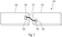
- Fig.1 illustrates a first PCBA interconnected with a second PCBA by an elastic connector, according to an embodiment of the present invention.
- the PCB interconnection assembly 100 of a non-limiting embodiment comprises a first PCBA 105, a second PCBA 110, and an elastic connector 115 interconnecting the first PCBA 105 and the second PCBA 110.
- the first PCBA 105 and the second PCBA 110 may be disposed with one or more electronic components.
- one or more light sources (for instance, Light Emitting Diodes, also known as LEDs) may be provided on the top face of the first PCBA 105; and control circuitry to drive the one or more light sources may be provided on the top face of the second PCBA 110.
- the elastic connector 115 is elastically deformable. It is a metal tongue with one or more bendings.
- exemplary elastic connectors 115a, 115b, and 115c are shown in the Fig.2a to Fig.2c , respectively.
- the elastic connectors 115 includes a first end 120 and a second end 125 opposite to the first end 120.
- the elastic connectors 115 is elastically deformable, where the first end 120 (shown in Fig.1 ) of the elastic connector 115 is fixed to the first PCBA 105 on a solder pad 130 arranged on the top face of the first PCBA 105, and a second end 125 (shown in Fig.1 ) is adapted to be pressed against a contact zone 135 of the second PCBA 110 by elastic deformation of the elastic connector 115, to engage the second end 125 to the contact zone 125 to establish the electrical and physical connection between the first PCBA 105 and the second PCBA 110.
- the present invention automates the assembly process of interconnecting PCBAs.
- the shape of the tongue can be dimensioned to accommodate the different angles between the PCBAs 105, 110.
- the shape of the tongue can be dimensioned to accommodate an angle comprised between -90 degrees and +90 degrees, between the first PCBA 105 and the second PCBA 110.
- the first PCBA 105 and the second PCBA 110 can be connected by a plurality of elastic connectors arranged side by side.
- the number of elastic connectors 115 are at least three so as to allow for one LED power supply connection, a ground connection, and a connection for transmission of data from the LED regarding parameters such as LED BIN and/or LED temperature.
- the contact zone 135 and/or the second end 125 of the elastic connector is plated with gold finishing. This gold finishing ensures to withstand vibrations and mechanical stress between PCBAs 105, 110 during the operation of the vehicle. It is to be understood that the second end 125 of the elastic connector 115 and/or the contact zone 135 may be plated with other suitable material that allows it to withstand vibrations and mechanical stress between PCBAs 105, 110 during the operation of the vehicle.
- the first PCBA 105 and the second PCBA 110 are of same type PCBs. In another non-limiting embodiment of the present invention, the first PCBA 105 and the second PCBA 110 are of different type PCBs.
- the first PCBA 105 is IMS PCB and the second PCBA 110 is FR4 PCB. In another example, the first PCBA 105 is FR4 PCB and the second PCBA 110 is IMS PCB.
- the first PCBA 105 is FR4 PCB and the second PCBA 110 is IMS PCB.
- the first PCBA 105 is FR4 PCB and the second PCBA 110 is FR4 PCB. Further, in another example, the first PCBA 105 is IMS PCB and the second PCBA 110 is IMS PCB.
- the present embodiments are discussed with regard to interconnection of two PCBAs, however it is understood to a person skilled in that multiple PCBAs can be interconnected by using one or more elastic connectors.
- PCBAs are generally supported on a heat sink (not shown in Fig.1 ).
- the heat sink may be adapted to dissipate heat generated by light sources.
- the heat sink may be monobloc or a heat sink assembly made of heat sink parts.
- the PCBAs 115, 110 are mounted on different heat sink parts.
- at least one PCBA is mounted on the heat sink.
- first PCBA 105 and the second PCBA 110 by using the elastic connector 115.
- three different non-limiting embodiments of interconnecting the first PCBA 105 and the second PCBA 110 are discussed herein.
- PCB interconnecting assembly 300 is shown in Fig.3 .
- the first end 120 of the elastic connector 115 is soldered or welded onto one of solder pads arranged on the top side of the first PCBA 105 and the second end 125 of the elastic connector 115 is engaged to the contact zone arranged on the bottom side of the second PCBA 110.
- the first PCBA 115 is IMS PCB which accommodates one or more light sources 305 as shown in Fig.3 .
- the second PCBA 110 is secured to a base of a heat sink assembly 310 by a fastening means 315.
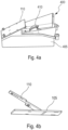
- a lighting module 400 in which the angled PCBAs are interconnected by using an elastic connector is shown, according to one preferred embodiment of the invention.
- the Fig.4b illustrates angled PCBAs connected by an elastic connector.
- the exemplary lighting module 400 includes a heat sink assembly 405, one or more reflectors 410 and a PCB interconnect assembly, which is clearly depicted in the Fig.4b .
- a beam originating from the light sources is first reflected on a primary reflector, towards a secondary reflector that then projects it through a lens of a vehicle headlight, towards an exterior of the headlight.
- the first PCBA 105 is positioned horizontally.
- the first PCBA 105 includes an IMS PCB.
- the first PCBA 105 is in direct contact with the heat sink 405, thus, heat dissipation performance can be improved.
- the one or more reflectors 410 are positioned directly over the light sources mounted on the first PCBA. This ensures to improve the optical performance as the one or more reflectors 410 can be positioned accurately over the light sources, and hence results in improving optical performance.
- the second PCBA 110 holds the driver circuitry is angled with respect to the first PCBA 105, and extends over the one or more reflectors 410, which are at least partially supported by the first PCBA 105.
- This disposition of the second PCBA 110 with respect to the first PCBA 105 allows to reduce the depth of the lighting module assembly.
- the EMC performance can be enhanced.
- the angled connection of the PCBAs is realised by the elastic connector 115 and the angled connection of PCBAs ensures to provide a high performance compact lighting module, while meeting the thermal constraints and space constraints.
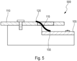
- FIG.5 Another non-limiting embodiment of PCB interconnection assembly 500 is shown in Fig.5 As can be seen in the Fig.5 , the first end 120 of the elastic connector 115 is soldered or welded onto a solder pad arranged on a top side of the second PCBA 110 and the second end of the elastic connector 115 extends through a hole in the second PCBA 110 to connect the second end 125 of the elastic connector to a contact zone provided on the top side of the first PCBA 105.
- This type of connection is advantageous when the second PCBA 110 is of longer length compared to the length of the first PCBA 105.
- This type of arrangement is useful when both the PCBAs are of the same type and when the lighting module has depth constraints. For example, in some lighting modules, it is required to connect two IMS PCBAs on which light sources have to be mounted. In such cases, this type of connection is useful to connect two IMS PCBAs while meeting the depth constraints.
- FIG.6 Another non-limiting embodiment of PCB interconnect assembly 600 is shown in Fig.6 .
- the first end 120 of the elastic connector 115 is soldered or welded on the top side of the first PCBA 105 and the second end 125 of the elastic connector 115 is engaged to the contact zone arranged on the top side of the second PCBA 110.
- This type of arrangement between PCBAs 105, 110 requires further less space for elastic connection compared to the arrangement shown in the embodiment 300.
- This type of arrangement is useful when the PCBAs 105a, 105b, 105c are required to be arranged horizontally as shown in the Fig.7 .
- this type of arrangement is useful in lighting modules which have height constraints, for example, thin lighting modules.
- compactness between the PCBAs 105, 110 is enhanced and hence advantageous for realizing a compact lighting module.
- FIG.8 An exemplary lighting module according to another preferred embodiment is shown in the Fig.8 .
- one or more reflectors (not shown in the Figures) is adapted to reflect the light towards an exit lens (not shown in the Figures), which is slanted.
- the one or more reflectors is adapted to reflect light to perform high performance front lighting functions, in particular functions providing a beam with a horizontal cut-off, a horizontal orientation has to be kept for the PCBAs.
- it is required to arrange in stairs so as to follow the slant of the exit lens; for instance, the PCBAs may be laid out along an axis transversal to the main driving direction.
- the horizontally arranged PCBAs 105a, 105b, 105c are interconnected by elastic connectors 115a, 115b as shown in the Fig.7 , and this arrangement may result in reducing cost and saving space taken by the wire harness.
- the present invention is related to a vehicle headlamp comprising one or more of the exemplary lighting modules.
- the embodiments of the present invention provide an automotive lighting module in which PCBs are interconnected by a mechanism which eliminates the need for wiring harness and conventional connectors, and still provide a mechanical and electrical interconnection between the PCBs, while meeting thermal constraints, optical constraints, as well as EMC constraints.
Landscapes
- Engineering & Computer Science (AREA)
- General Engineering & Computer Science (AREA)
- Microelectronics & Electronic Packaging (AREA)
- Manufacturing & Machinery (AREA)
- Arrangement Of Elements, Cooling, Sealing, Or The Like Of Lighting Devices (AREA)
Priority Applications (4)
| Application Number | Priority Date | Filing Date | Title |
|---|---|---|---|
| EP22159320.5A EP4240122A1 (fr) | 2022-03-01 | 2022-03-01 | Module d'éclairage avec ensembles pcb interconnectés |
| PCT/EP2023/055189 WO2023166062A1 (fr) | 2022-03-01 | 2023-03-01 | Module d'éclairage à ensembles pcb interconnectés |
| CN202380022499.3A CN118715878A (zh) | 2022-03-01 | 2023-03-01 | 具有互连的pcb组件的照明模块 |
| US18/841,491 US12565974B2 (en) | 2022-03-01 | 2023-03-01 | Lighting module with interconnected PCB assemblies |
Applications Claiming Priority (1)
| Application Number | Priority Date | Filing Date | Title |
|---|---|---|---|
| EP22159320.5A EP4240122A1 (fr) | 2022-03-01 | 2022-03-01 | Module d'éclairage avec ensembles pcb interconnectés |
Publications (1)
| Publication Number | Publication Date |
|---|---|
| EP4240122A1 true EP4240122A1 (fr) | 2023-09-06 |
Family
ID=80683844
Family Applications (1)
| Application Number | Title | Priority Date | Filing Date |
|---|---|---|---|
| EP22159320.5A Pending EP4240122A1 (fr) | 2022-03-01 | 2022-03-01 | Module d'éclairage avec ensembles pcb interconnectés |
Country Status (4)
| Country | Link |
|---|---|
| US (1) | US12565974B2 (fr) |
| EP (1) | EP4240122A1 (fr) |
| CN (1) | CN118715878A (fr) |
| WO (1) | WO2023166062A1 (fr) |
Citations (5)
| Publication number | Priority date | Publication date | Assignee | Title |
|---|---|---|---|---|
| EP2197047A1 (fr) * | 2007-08-28 | 2010-06-16 | Panasonic Electric Works Co., Ltd | Dispositif électroluminescent |
| US20110090691A1 (en) * | 2009-10-15 | 2011-04-21 | Joshua Josiah Markle | Lamp assemblies and methods of making the same |
| US20140218954A1 (en) * | 2013-02-06 | 2014-08-07 | Samsung Electronics Co., Ltd. | Light-emitting device package module |
| US20170082257A1 (en) * | 2015-09-17 | 2017-03-23 | Young Jeong YOON | Light source module and lighting device having the same |
| EP3389189A1 (fr) * | 2015-12-07 | 2018-10-17 | Mitsubishi Electric Corporation | Module hyperfréquence et module haute fréquence |
Family Cites Families (1)
| Publication number | Priority date | Publication date | Assignee | Title |
|---|---|---|---|---|
| FR2914984B1 (fr) * | 2007-04-13 | 2013-11-08 | Valeo Vision | Support electronique flexible equipe, supportant au moins une diode electroluminescente, et procede de fabrication associe. |
-
2022
- 2022-03-01 EP EP22159320.5A patent/EP4240122A1/fr active Pending
-
2023
- 2023-03-01 US US18/841,491 patent/US12565974B2/en active Active
- 2023-03-01 CN CN202380022499.3A patent/CN118715878A/zh active Pending
- 2023-03-01 WO PCT/EP2023/055189 patent/WO2023166062A1/fr not_active Ceased
Patent Citations (5)
| Publication number | Priority date | Publication date | Assignee | Title |
|---|---|---|---|---|
| EP2197047A1 (fr) * | 2007-08-28 | 2010-06-16 | Panasonic Electric Works Co., Ltd | Dispositif électroluminescent |
| US20110090691A1 (en) * | 2009-10-15 | 2011-04-21 | Joshua Josiah Markle | Lamp assemblies and methods of making the same |
| US20140218954A1 (en) * | 2013-02-06 | 2014-08-07 | Samsung Electronics Co., Ltd. | Light-emitting device package module |
| US20170082257A1 (en) * | 2015-09-17 | 2017-03-23 | Young Jeong YOON | Light source module and lighting device having the same |
| EP3389189A1 (fr) * | 2015-12-07 | 2018-10-17 | Mitsubishi Electric Corporation | Module hyperfréquence et module haute fréquence |
Also Published As
| Publication number | Publication date |
|---|---|
| US20250172266A1 (en) | 2025-05-29 |
| CN118715878A (zh) | 2024-09-27 |
| US12565974B2 (en) | 2026-03-03 |
| WO2023166062A1 (fr) | 2023-09-07 |
Similar Documents
| Publication | Publication Date | Title |
|---|---|---|
| KR101231406B1 (ko) | 차량용 전조등 | |
| CN101153693B (zh) | 车辆用灯具 | |
| EP2474777B1 (fr) | Dispositif émetteur de lumière et phare de véhicule | |
| EP2623850A1 (fr) | Module de circuit, module émetteur de lumière et lampe de véhicule | |
| US8366305B2 (en) | Vehicle lamp | |
| CN111372815B (zh) | 照明模块和车辆头灯 | |
| CN108692289B (zh) | 具有电连接保护的折叠式热沉 | |
| US8833992B2 (en) | Automotive headlamps | |
| US12565974B2 (en) | Lighting module with interconnected PCB assemblies | |
| US7626212B2 (en) | Light-emitting device and light source apparatus using the same | |
| EP3450833B1 (fr) | Dispositif électronique et module d'éclairage | |
| EP4395078B1 (fr) | Dispositif lumineux pour automobile | |
| EP4659548A1 (fr) | Support pour un dispositif de montage en surface, ensemble et support de circuit | |
| CN114787558B (zh) | 用于机动车辆的照明装置 | |
| KR102883001B1 (ko) | 차량용 램프 | |
| KR102561717B1 (ko) | Led용 pcb 기판 및 pcb 조립체 | |
| EP3434968A1 (fr) | Ensemble et procédé électronique automobile | |
| EP3386278A1 (fr) | Carte de circuit imprimé et dispositif d'éclairage | |
| EP4634568A1 (fr) | Module d'éclairage pourvu de del à contact supérieur et de del à montage en surface | |
| US20100188865A1 (en) | Light source module and vehicular lamp |
Legal Events
| Date | Code | Title | Description |
|---|---|---|---|
| PUAI | Public reference made under article 153(3) epc to a published international application that has entered the european phase |
Free format text: ORIGINAL CODE: 0009012 |
|
| STAA | Information on the status of an ep patent application or granted ep patent |
Free format text: STATUS: THE APPLICATION HAS BEEN PUBLISHED |
|
| AK | Designated contracting states |
Kind code of ref document: A1 Designated state(s): AL AT BE BG CH CY CZ DE DK EE ES FI FR GB GR HR HU IE IS IT LI LT LU LV MC MK MT NL NO PL PT RO RS SE SI SK SM TR |
|
| STAA | Information on the status of an ep patent application or granted ep patent |
Free format text: STATUS: REQUEST FOR EXAMINATION WAS MADE |
|
| 17P | Request for examination filed |
Effective date: 20240306 |
|
| RBV | Designated contracting states (corrected) |
Designated state(s): AL AT BE BG CH CY CZ DE DK EE ES FI FR GB GR HR HU IE IS IT LI LT LU LV MC MK MT NL NO PL PT RO RS SE SI SK SM TR |