EP4240438B1 - Brustpumpenvorrichtung und steuergerät für die vorrichtung und steuerungsverfahren - Google Patents
Brustpumpenvorrichtung und steuergerät für die vorrichtung und steuerungsverfahren Download PDFInfo
- Publication number
- EP4240438B1 EP4240438B1 EP21782445.7A EP21782445A EP4240438B1 EP 4240438 B1 EP4240438 B1 EP 4240438B1 EP 21782445 A EP21782445 A EP 21782445A EP 4240438 B1 EP4240438 B1 EP 4240438B1
- Authority
- EP
- European Patent Office
- Prior art keywords
- mode
- breast
- pressure
- low energy
- expression
- Prior art date
- Legal status (The legal status is an assumption and is not a legal conclusion. Google has not performed a legal analysis and makes no representation as to the accuracy of the status listed.)
- Active
Links
Images


Classifications
-
- A—HUMAN NECESSITIES
- A61—MEDICAL OR VETERINARY SCIENCE; HYGIENE
- A61M—DEVICES FOR INTRODUCING MEDIA INTO, OR ONTO, THE BODY; DEVICES FOR TRANSDUCING BODY MEDIA OR FOR TAKING MEDIA FROM THE BODY; DEVICES FOR PRODUCING OR ENDING SLEEP OR STUPOR
- A61M1/00—Suction or pumping devices for medical purposes; Devices for carrying-off, for treatment of, or for carrying-over, body-liquids; Drainage systems
- A61M1/06—Milking pumps
- A61M1/069—Means for improving milking yield
- A61M1/0693—Means for improving milking yield with programmable or pre-programmed sucking patterns
-
- A—HUMAN NECESSITIES
- A61—MEDICAL OR VETERINARY SCIENCE; HYGIENE
- A61M—DEVICES FOR INTRODUCING MEDIA INTO, OR ONTO, THE BODY; DEVICES FOR TRANSDUCING BODY MEDIA OR FOR TAKING MEDIA FROM THE BODY; DEVICES FOR PRODUCING OR ENDING SLEEP OR STUPOR
- A61M1/00—Suction or pumping devices for medical purposes; Devices for carrying-off, for treatment of, or for carrying-over, body-liquids; Drainage systems
- A61M1/06—Milking pumps
-
- A—HUMAN NECESSITIES
- A61—MEDICAL OR VETERINARY SCIENCE; HYGIENE
- A61M—DEVICES FOR INTRODUCING MEDIA INTO, OR ONTO, THE BODY; DEVICES FOR TRANSDUCING BODY MEDIA OR FOR TAKING MEDIA FROM THE BODY; DEVICES FOR PRODUCING OR ENDING SLEEP OR STUPOR
- A61M2205/00—General characteristics of the apparatus
- A61M2205/33—Controlling, regulating or measuring
- A61M2205/3306—Optical measuring means
-
- A—HUMAN NECESSITIES
- A61—MEDICAL OR VETERINARY SCIENCE; HYGIENE
- A61M—DEVICES FOR INTRODUCING MEDIA INTO, OR ONTO, THE BODY; DEVICES FOR TRANSDUCING BODY MEDIA OR FOR TAKING MEDIA FROM THE BODY; DEVICES FOR PRODUCING OR ENDING SLEEP OR STUPOR
- A61M2205/00—General characteristics of the apparatus
- A61M2205/33—Controlling, regulating or measuring
- A61M2205/3331—Pressure; Flow
-
- A—HUMAN NECESSITIES
- A61—MEDICAL OR VETERINARY SCIENCE; HYGIENE
- A61M—DEVICES FOR INTRODUCING MEDIA INTO, OR ONTO, THE BODY; DEVICES FOR TRANSDUCING BODY MEDIA OR FOR TAKING MEDIA FROM THE BODY; DEVICES FOR PRODUCING OR ENDING SLEEP OR STUPOR
- A61M2205/00—General characteristics of the apparatus
- A61M2205/33—Controlling, regulating or measuring
- A61M2205/3331—Pressure; Flow
- A61M2205/3334—Measuring or controlling the flow rate
-
- A—HUMAN NECESSITIES
- A61—MEDICAL OR VETERINARY SCIENCE; HYGIENE
- A61M—DEVICES FOR INTRODUCING MEDIA INTO, OR ONTO, THE BODY; DEVICES FOR TRANSDUCING BODY MEDIA OR FOR TAKING MEDIA FROM THE BODY; DEVICES FOR PRODUCING OR ENDING SLEEP OR STUPOR
- A61M2205/00—General characteristics of the apparatus
- A61M2205/50—General characteristics of the apparatus with microprocessors or computers
-
- A—HUMAN NECESSITIES
- A61—MEDICAL OR VETERINARY SCIENCE; HYGIENE
- A61M—DEVICES FOR INTRODUCING MEDIA INTO, OR ONTO, THE BODY; DEVICES FOR TRANSDUCING BODY MEDIA OR FOR TAKING MEDIA FROM THE BODY; DEVICES FOR PRODUCING OR ENDING SLEEP OR STUPOR
- A61M2205/00—General characteristics of the apparatus
- A61M2205/82—Internal energy supply devices
- A61M2205/8206—Internal energy supply devices battery-operated
- A61M2205/8212—Internal energy supply devices battery-operated with means or measures taken for minimising energy consumption
Definitions
- the invention relates to a breast pump device and a method of operating a breast pump device.
- breast pumps typically have a stimulation mode to activate the milk ejection reflex (MER), and an expression mode.
- MER milk ejection reflex
- the transition from the stimulation mode to the expression mode is not based on detection of MER. It is either time-based, i.e. a fixed time after switching on, or manually controlled by pushing a button.
- WO 2011/010255 discloses a breast pump with many modes, including a stimulation mode (called a let-down mode) and an expression mode. It can switch from the stimulation mode to the expression mode automatically, based on various sensed values.
- the breast feeding session continues until a defined quantity of milk has been collected, or a defined time has elapsed, or the mother chooses to stop.
- US 2020/0078503 discloses a breast pump in which the sensing of milk flow parameters is used to control automatically the breast pumping process.
- One proposed mode of operation alternates between a stimulation mode and an expression mode.
- WO 2016/014469 discloses a breast pump having a sensor e.g. for measuring pressure, so that pressure waveforms may be plotted during operation of the breast pump.
- the waveforms can be used to determine when milk flow initiates. Cycle frequencies or pressure amplitudes can be controlled based on feedback to optimize milk extraction.
- WO 00/57934 discloses a breast pump which implements a non-nutritive sucking cycle (i.e. a stimulation cycle with rapidly repeating low vacuum pulses) and a nutritive sucking cycle (i.e. an expression cycle with slowly repeating stronger vacuum pulses).
- a non-nutritive sucking cycle i.e. a stimulation cycle with rapidly repeating low vacuum pulses
- a nutritive sucking cycle i.e. an expression cycle with slowly repeating stronger vacuum pulses.
- a controller for a breast pump device wherein the controller is for controlling operation of a pressure source of the breast pump device to apply an under-pressure, the controller comprising:
- the output is then for controlling operation of the pressure source to follow a sequence comprising the stimulation mode followed by alternating expression modes and low energy modes.
- the low energy mode uses less power than either the stimulation mode or the expression mode.
- the breast pumping session thus comprises a plurality of time periods with the low energy mode and a plurality of time periods with the expression mode.
- This controller monitors the milk flow during (rather than only at the start) of a breast pumping session, so that throughout the breast pumping session the breast pump may be switched between a low energy mode and an expression mode.
- the expression mode is used at times when milk is flowing, and the low energy mode is used at times when the milk flow has stopped, or is declining (so indicating an end of a period of expression), or has dropped below a threshold level.
- the time duration of the most electrically power demanding mode i.e. the expression mode, can be kept to a minimum.
- There may be multiple low energy mode times and multiple expression mode times (depending on the profile of the milk flow of the mother).
- a breast pumping session starts with a stimulation mode, followed by an expression mode.
- the expression mode is interrupted with the low energy modes.
- stimulation is at the beginning of breast pumping, and there are then low energy modes distributed with the expression modes throughout the breast pumping session.
- the low energy mode has a different pressure profile to both the initial stimulation mode and the expression mode. It may for example have a frequency corresponding to the expression mode but a lower under pressure level. It may have different dwell in time or dwell out time compared to the expression mode.
- the low energy mode is "low energy” in that it has lower electrical power consumption (i.e. energy usage per unit time) than the expression mode or the stimulation mode.
- the invention is in part based on the recognition that within the time generally considered to be the milk expression time, there are time periods of high milk flow and time periods of low or no milk flow, creating a locally varying milk flow pattern.
- the low energy mode is used during the periods of low or no milk flow.
- the low energy mode may be considered to be any mode which maintains a cyclic pressure waveform, suitable while waiting for milk expression. It has a different pressure profile to the expression mode, in particular a reduced maximum under-pressure level as it is intended to save power rather than achieve the greatest milk flow. It also has a different pressure profile to the initial stimulation mode.
- the breast pumping session preferably comprises a continuous sequence of the time periods of the low energy mode and the expression mode.
- the continuous sequence means that these different modes (with the same pressure profile each time or with different pressure profiles) are used multiple times in the same session (rather than once each is separate sessions).
- the low energy mode has a lower electrical power consumption than the expression mode and a lower electrical power consumption than the stimulation mode.
- the low energy mode for example has a lower maximum under-pressure level than the expression mode. This enables the reduced power consumption.
- the expression mode for example has a maximum under-pressure above 200 mbar (20 kPa) and the low energy mode has a maximum under-pressure below 200 mbar (20 kPa).
- the under-pressure level is the pressure level relative to (and below) the ambient pressure level.
- the input signal may indicate the detection of (one or more of) milk drops or a cumulative milk flow or a milk flow gradient or a trend in the milk flow gradient.
- the input signal can be used to indicate that a local period of milk expression is coming to an end or has ended.
- the controller may be adapted to derive a relationship between the cumulative milk flow and time for a particular user, and to derive a program of operation of the pressure source for the particular user from the relationship.
- the controller can learn from the sensing to derive a customized pressure sequence for a particular user. This customized pressure sequence may then have lower power consumption than when sensing feedback is used, because the sensor may then be deactivated.
- the invention also provides breast pump device, comprising
- the sensor for example comprises an optical sensor. This may be used to detect the passage of milk droplets during breast pumping, for example between the breast receiving portion and a collection vessel.
- the sensor for example comprises an optical emitter arrangement, an optical detector arrangement and an output for providing a signal indicating the presence milk expressed.
- the device preferably comprises a battery-operated device.
- the electrical efficiency gains enable a prolonged battery life.
- the invention also provides a computer-implemented non-therapeutic method of controlling a breast pump device, the breast pump device comprising at least one breast receiving portion configured to receive a breast of a user and a pressure source coupled to the at least one breast receiving portion and being configured to generate at least an under-pressure, the method comprising:
- the method comprises controlling operation of the pressure source to follow a sequence comprising the stimulation mode followed by alternating expression modes and low energy modes.
- the breast pumping session thus may comprise a plurality of time periods with the low energy mode and a plurality of time periods with the expression mode.
- the low energy mode preferably has a lower electrical power consumption and a lower maximum under-pressure level than the expression mode.
- the input signal indicates the detection of milk drops or a milk flow level or a milk flow gradient.
- the low energy mode for example has:
- the method may be implemented in software.
- the invention provides a breast pump device and a controller for operating a pressure source of the breast pump device.
- a milk flow is monitored during a breast pumping session.
- the pressure source is controlled in dependence on the flow, thereby to switch, during the breast pumping, between a first pressure profile of the pressure source for a low energy mode and a second pressure profile of the pressure source for an expression mode.
- the breast pumping session may then for example comprise a plurality of time periods with the low energy mode and a plurality of time periods with the expression mode, in order to reduce electrical power consumption.
- FIG. 1 shows a breast pump system in accordance with the invention.
- the breast pump system 1 comprises a breast pump 2, also known as an expression unit, and an operating unit 3.
- the operating unit is basically a pump unit (vacuum pump), associated hardware, and a pump controller 3'.
- the breast pump 2 and the operating unit 3 are connected by a hose 4.
- the hose 4 provides a fluid communication between the breast pump 2 and the operating unit 3.
- the hose 4 may also be used to provide an electrical connection between the breast pump 2 and the operating unit 3.
- the hose 4 may supply an operating signal or electrical power between the breast pump and the operating unit.
- the operating unit 3 is directly mounted and connected to the breast pump 2.
- the breast pump 2 has a main body 5, a funnel 6 and a collection vessel 7.
- the collection vessel 7 collects milk expressed from a user's breast and may take the form of a feeding bottle or bag or any suitable container.
- the collection vessel 7 is attached to the main body 5 by a screw fitting, although it will be understood that alternative releasable attachment means may be used, such as clips (not shown).
- the breast-receiving funnel 6 extends from the main body 5.
- the funnel 6 is configured to receive the breast of a user.
- the funnel 6 has a mouth 8 and a throat 9.
- the mouth 8 is open at an outer end of the funnel 6 to receive a user's breast, and the funnel 6 converges from the outer end towards the throat 9 to form a hollow recess in which a breast is received.
- the main body 5 fluidly connects the funnel 6 to the collection vessel 7.
- a fluid passageway 10 (shown in Figure 2 ) is formed through the main body 5 from the breast receiving space of the funnel 6 to the collection vessel 7.
- the main body 5 is formed from an outer shell.
- the main body 5 is integrally formed with the funnel 6, however it will be understood that the funnel 6 may be detachable.
- the main body 5 is formed from polypropylene, although it will be understood that alternative suitable materials may be used.
- Figure 1 shows a sensor 30 for sensing milk flow information.
- the controller 3' uses this information to adapt the pressure profile applied, as explained below.
- a chamber 12 is formed in the main body 5.
- the chamber forms part of a vacuum path.
- the chamber 12 is in fluid communication with the fluid passageway 10 between the funnel 6 and the collection vessel 7.
- the chamber 12 has a vacuum port 13.
- the vacuum port 13 provides a port to communicate with the operating unit 3.
- the hose 4 is mountable to the vacuum port 13 to fluidly connect the chamber 12 with the operating unit 3.
- a membrane 14 is received in the chamber 12.
- the membrane 14, also known as a diaphragm, is flexible.
- An outer rim of the membrane 14 is mounted to the chamber 12.
- the membrane 14 separates the chamber 12 into a first space 15 and a second space 16.
- the first space 15 communicates with the vacuum port 13.
- the first space 15 forms part of a first section of the vacuum path.
- the second space 16 communicates with the fluid passageway 10 between the breast receiving space of the funnel 6 and the collection vessel 7.
- the second space 16 forms part of a first section of the vacuum path.
- a one-way valve 17 is disposed in the fluid passageway 10.
- the one-way valve 17 prevents a pressure reduction being formed in the collection vessel 7.
- the one-way valve is for example a duckbill valve.
- the membrane 14 is for example formed from silicone. However, it will be understood that the membrane 14 may be formed from another suitable material.
- the flexible membrane 14 has a predefined shape.
- the membrane 14 has a substantially cup-shaped arrangement in a neutral condition. That is, when the membrane 14 is received in the chamber 12, but has not been deformed.
- the membrane 14 may have an alternative shape.
- the operating unit 3 comprises a pump controller 3', a power source, a motor and a pump unit actuated by the motor.
- the pump unit is configured to generate and release a pressure reduction (i.e. vacuum) in the vacuum path, for example using a pressure relief valve separate to the pump unit, although these may be combined into a single unit.
- the controller 3' controls operation of these components of the operating unit 3.
- the controller 3' operates the pump unit with sequence of strokes, each stroke comprising the vacuum generation phase and the vacuum release phase.
- vacuum generation the breast is stimulated to express milk.
- This milk flows to the fluid passageway 10.
- the vacuum release phase the milk passes through the one-way valve 17 into the collection vessel.
- a small opening is for example provided to allow air to escape from the bottle. This may be located at the screw connection.
- the invention relates to the pressure profile applied during a breast pump session, and may be applied to any known breast pump design.
- Figure 3 shows in schematic form an example of a typical pressure cycle during expression, applied by the pump unit of the operating unit 3.
- the control signal to the pump unit cycles between a baseline vacuum “Baseline_Vac” and a maximum vacuum (i.e. a maximum under-pressure) "Max_Vac".
- TTV time to (maximum) vacuum
- DI time to atmosphere
- TTA time to atmosphere
- DO dwell-out time
- the maximum under-pressure may be higher, for example 350 mbar (35 kPa) and the the durations may differ.
- the cycle time is generally of the order of 1 to 2 seconds.
- Figure 4 shows a more realistic pressure waveform. It also shows an arrow representing the vacuum rate.
- the milk flow pattern evolves mainly due to the occurrence of milk ejection reflex (MER).
- MER milk ejection reflex
- a typical pattern is shown in Figure 5 for a full breast pumping session of 800 seconds.
- a stimulation mode takes place during time period 50, for example with duration 50 seconds.
- the stimulation mode has a faster frequency hence with a shorter cycle time of around 0.5 seconds, and a lower vacuum, for example a maximum under-pressure level of 150 mbar (15 kPa).
- the expression mode conventionally takes place during the remainder of the breast feeding session.
- Plot 52 shows the cumulative mass of milk collected over time (using the left y-axis scale, grams).
- Plot 54 shows the milk flow rate (using the right y-axis scale, g/s) hence the first derivative of plot 52.
- the derivative of the flow rate signal 52 (not shown) has positive periods when the flow rate is increasing and negative periods when the flow rate is decreasing.
- the invention provides a system for controlling the pressure source to switch between the expression pressure profile and and a low energy pressure profile (in both directions) and typically multiple times during a breast pumping session.
- the different pressure profiles are chosen in dependence on the milk flow, captured by means of the sensor 30.
- Figure 6 shows the same plots as Figure 5 , but shows that the low energy mode may be used multiple times within the breast feeding session. Three additional periods 80 of a low energy mode have been added.
- the switching to the low energy mode may be based on analysis of the cumulative milk volume (curve 52) or milk flow rate (curve 54) or trends in the milk flow rate (derivative of curve 54).
- Figure 6 shows that a drop in the milk flow rate from a local peak, by a given amount, indicates that an expression period is coming to an end.
- a particular gradient threshold of the milk flow rate i.e. when curve 54 is increasing at a certain rate may for example be used to trigger the expression mode.
- One example involves switching to the low energy mode when a drop in milk flow rate (plot 54) from a local peak has been detected, e.g. a 30% drop. This triggers a switch in the vacuum profile setting. Similarly, an increase of milk flow rate by a certain amount from a local minimum may be used to switch back to the expression mode.
- a drop in milk flow rate plot 54
- Another example is to detect the slope of the milk flow rate profile 54, and switch to the low energy mode when the slope has a transition from positive to negative.
- the system can switch to the expression mode when the slope has a transition from negative to positive.
- a waiting time may be implemented before the switch, e.g. 10 seconds, after the transition to a negative slope to allow completion of that local period of milk expression.
- time periods with the low energy mode 3 in this example plus the initial stimulation mode
- time periods (4 in this example) with the expression mode 4 in this example
- the number will depend on the number of MERs, which is typically from 1 to about 10.
- the time periods of the low energy mode for example have a lower under-pressure than the expression mode, for example with the 15 kPa under-pressure of the stimulation mode instead of the 30 kPa under-pressure of the expression mode. They may instead have an even lower under-pressure than the stimulation mode.
- the low energy mode may comprise a long duration cycle, thereby reducing the switching energy.
- the low energy mode cycles may for example have the same period as time periods of the expression mode, i.e. the longer duration (e.g. 1.5s) cycles explained above.
- the low energy mode may have different time profile and pressure levels to both the stimulation mode and the expression mode.
- the low energy mode may for example have the same rise and fall times (TTV, TTA) of the expression mode, but with increased dwell in time DI and/or and dwell out time DO thereby extending the cycle to be longer than the cycle time of the expression mode.
- the low energy mode may for example have a longer (i.e. lower gradient i.e. slower) rising time (TTV). Again, this will extend the cycle period.
- TTV rising time
- the low energy mode is designed to reduce power consumption while still enabling expression to be restarted.
- the breast pump thus switches both from the stimulation mode to the expression mode (as is known) and also switches from the expression mode to the low energy mode when it is detected that a short term localized (in time) period of expression is coming to an end or has come to an end.
- the breast pump then toggles between the low energy mode and the expression mode.
- the sensing to determine when to switch between modes may be performed in various ways.
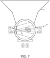
- Figure 7 shows an example of the sensor 30 implemented as an optical sensor located at the neck portion of the expression kit. It shows a cross section through the fluid passageway 10 looking from above. It shows the valve 17 and a milk droplet 60 at the valve. Expressed milk passes this neck portion before it reaches the bottom of the collection vessel. Droplets can thereby be sensed as they pass the neck portion.
- the detection may be based on detecting the interruption of a light beam, or it may be based on measurement of a change in reflection or scattering of light back from a layer of milk on the inner wall of the expression kit.
- the optical sensor may comprise a snap-on holder, which can snap onto the neck portion of the expression kit.
- the emitter or emitters and detector or detectors may be mounted externally of the expression kit.
- the design may make use of the diffuse properties of the material used for making the expression kit, such as silicone.
- a LED having a large divergence angle (approximately 120 degrees) may be used as the illumination source and the light that exits internally after passage through the material exhibits a near diffuse illumination pattern illuminating the whole head of the bottle. This enables to detect any small changes in the intensity on a detector due to the changes in the absorption and scattering induced by the flowing milk. Thus, it may suffice to have a single emitter and a single detector.
- the example of Figure 9 instead comprises three emitters (LEDs) Led0, Led1, Led2 and three detectors (photodiodes) PD0, PD1, PD2.
- the signals obtained from the detectors are processed to determine the presence of a milk drop based on changes in the intensity of light detected in all detectors.
- sensor designs are possible, for example based on acoustic sensing (sensing the sound of a falling droplet). Indeed, any known sensor design may be used for detecting or measuring a flow of liquid.
- the presence of milk drops is sensed and used to switch between settings.
- the low energy mode is switched on when no milk is detected and the expression mode is switched on when a drop is detected.
- the switching may be based on a threshold level of the milk flow volume, i.e. when a certain additional amount of flow has taken place (rather than just droplet).
- the switching may be based on the slope of the milk flow volume, i.e. the gradient of the milk flow volume curve and hence the flow rate.
- the switching may be based on the trend of the milk flow rate i.e. the second derivative of the milk flow volume curve.
- the pump can be switched to the low energy mode, and when the milk flow rate is increasing (positive second derivative), the pump can be switched to the expression setting.
- the sensing may be for droplet detection, for detection of a flow amount, for detection of a flow rate, or for detection of a trend in the flow rate. Any or all of these measures may be used to determine times when expression is taking place and times when it is ending or has ended.
- the breast pump has only the stimulation mode, which functions as the low energy mode, and the expression mode.
- the stimulation mode which functions as the low energy mode
- the expression mode there may be other modes, such as a massage mode and the low energy mode may be different to the initial stimulation mode.
- an initial stimulation mode is active.
- the sensor detects the milk and switches the pump setting to the expression mode.
- the pump is then switched back to the low energy mode (e.g. the stimulation mode) to save energy.
- the first type was the standard expression setting with a maximum under pressure of 350 mbar (35 kPa) and the second type was the alternation between the standard expression setting (again with a maximum under-pressure level of 350 mbar (35 kPa)) and a low energy setting (with a maximum under-pressure level of 150 mbar (15 kPa), when the milk flow is low or non-existent.
- the milk flow pattern of any individual mother has been shown to be similar, after first start of the milk flow. Therefore, after first determining the milk flow pattern, a program switching between the pump settings can be derived which is optimal for the pattern of that particular user. Thus, instead of continuous adaption of the pump profile, a personalized fixed program may be devised for the mother.
- This calibration routine may be applied once only, or periodically. For example, the calibration may be performed when there is mains power, and the fixed program may be used when operating from a battery, to save power.
- the method is a non-therapeutic method in that it is only used to enable a mother to express milk for feeding to an infant at a later time.
Landscapes
- Health & Medical Sciences (AREA)
- Heart & Thoracic Surgery (AREA)
- Biomedical Technology (AREA)
- Vascular Medicine (AREA)
- Engineering & Computer Science (AREA)
- Anesthesiology (AREA)
- Pediatric Medicine (AREA)
- Hematology (AREA)
- Life Sciences & Earth Sciences (AREA)
- Animal Behavior & Ethology (AREA)
- General Health & Medical Sciences (AREA)
- Public Health (AREA)
- Veterinary Medicine (AREA)
- External Artificial Organs (AREA)
Claims (14)
- Steuerung (3') für eine Milchpumpvorrichtung, wobei die Steuerung zum Steuern eines Betriebs einer Druckquelle (3) der Milchpumpvorrichtung ist, um einen Unterdruck anzuwenden, die Steuerung umfassend:einen Eingang (34) zum Empfangen eines Eingangssignals, das sich auf einen Milchfluss während eines Milchpumpvorgangs unter Verwendung der Milchpumpvorrichtung bezieht; undeinen Ausgang zum Steuern des Betriebs der Druckquelle abhängig von dem Eingangssignal, wobei der Ausgang zum Steuern des Betriebs der Druckquelle dient, um während des Milchpumpens zwischen drei Modi umzuschalten:einem Niedrigenergiemodus mit einem ersten Druckprofil der Druckquelle;einem Auspressmodus mit einem zweiten Druckprofil der Druckquelle; undeinem Stimulationsmodus mit einem dritten Druckprofil der Druckquelle, wobei das ersten bis dritte Druckprofil alle verschieden sind, dadurch gekennzeichnet, dassder Ausgang zur Steuerung des Betriebs der Druckquelle dient, um einer Sequenz zu folgen, die den Stimulationsmodus gefolgt von abwechselnden Auspressmodi und Niedrigenergiemodi umfasst.
- Steuerung nach Anspruch 1, wobei der Milchpumpvorgang eine kontinuierliche Abfolge von Zeitabschnitten des Niedrigenergiemodus und des Auspressmodus nach dem Stimulationsmodus umfasst.
- Steuerung nach Anspruch 1 oder 2, wobei der Energiesparmodus einen geringeren Stromverbrauch aufweist als der Auspressmodus und der Stimulationsmodus.
- Steuerung nach einem der Ansprüche 1 bis 3, wobei der Niedrigenergiemodus ein niedrigeres maximales Unterdruckniveau und/oder eine längere Verweilzeit und/oder eine längere Verweilzeit als der Auspressmodus aufweist.
- Steuerung nach einem der Ansprüche 1 bis 4, wobei der Auspressmodus einen maximalen Unterdruck von über 20 kPa und der Niedrigenergiemodus einen maximalen Unterdruck von unter 20 kPa aufweist.
- Steuerung nach einem der Ansprüche 1 bis 5, wobei das Eingangssignal mindestens eines von Folgenden angibt: die Erkennung von Milchtropfen; einen kumulativen Milchfluss; einen Milchflussgradienten; und einen Trend im Milchflussgradienten.
- Steuerung (3') nach Anspruch 6, die angepasst ist, um eine Beziehung zwischen dem kumulativen Milchfluss und der Zeit für einen bestimmten Benutzer abzuleiten und aus dieser Beziehung ein Betriebsprogramm für die Druckquelle für den bestimmten Benutzer abzuleiten.
- Milchpumpvorrichtung, umfassendmindestens einen Brustaufnahmeabschnitt (6), der angepasst ist, um die Brust eines Benutzers aufzunehmen;eine Druckquelle (3), die mit dem mindestens einen Brustaufnahmeteil gekoppelt und konfiguriert ist, um mindestens einen Unterdruck zu erzeugen;einen Sensor (30) zum Erzeugen eines Eingangssignals, das sich auf den Milchfluss während eines Milchpumpvorgangs bezieht; unddie Steuerung (3') nach einem der Ansprüche 1 bis 7.
- Milchpumpvorrichtung nach Anspruch 8, wobei der Sensor (30) einen optischen Sensor umfasst.
- Milchpumpvorrichtung nach Anspruch 9, wobei der Sensor (30) Folgendes umfasst:eine optische Emitteranordnung (Led0 - Led2);eine optische Detektoranordnung (PDO-PD2); undeinen Ausgang zum Bereitstellen eines Signals, das das Vorhandensein von ausgepresster Milch angibt.
- Milchpumpvorrichtung nach einem der Ansprüche 8 bis 10, umfassend eine batteriebetriebene Vorrichtung.
- Computerprogramm, umfassend Computerprogrammcode, der angepasst ist, um auf einer Steuerung einer Milchpumpvorrichtung ausgeführt zu werden, die Milchpumpvorrichtung umfassend:mindestens einen Brustaufnahmeabschnitt, der konfiguriert ist, um die Brust einer Benutzerin aufzunehmen;eine Druckquelle, die mit dem mindestens einen Brustaufnahmeteil gekoppelt und konfiguriert ist, um mindestens einen Unterdruck zu erzeugen; undeinen Sensor zum Erzeugen eines Eingangssignals, das sich auf den Milchfluss während eines Milchpumpvorgangs bezieht,wobei das Computerprogramm angepasst ist, um das folgende Verfahren zu implementieren:empfangen eines Eingangssignals (34), das sich auf einen Milchfluss während eines Milchpumpvorgangs unter Verwendung der Milchpumpvorrichtung bezieht; undsteuern eines Betriebs der Druckquelle (3) abhängig von dem Eingangssignal, um während des Milchpumpens umzuschalten zwischen:einem Niedrigenergiemodus mit einem ersten Druckprofil der Druckquelle;einem Auspressmodus mit einem zweiten Druckprofil der Druckquelle; undeinem Stimulationsmodus mit einem dritten Druckprofil der Druckquelle,wobei das ersten bis dritte Druckprofil alle verschieden sind, wobei das Verfahren ein Steuern des Betriebs der Druckquelle umfasst, um einer Sequenz zu folgen, die den Stimulationsmodus gefolgt von abwechselnden Auspressmodi und Niedrigenergiemodi umfasst.
- Computerprogramm nach Anspruch 12, wobei der Niedrigenergiemodus im Vergleich zu dem Auspressmodus die folgenden Eigenschaften aufweist:einen geringeren Stromverbrauch; undein niedrigeres maximales Unterdruckniveau und/oder eine längere Verweilzeit und/oder eine längere Verweilzeit und/oder eine längere Anstiegszeit.
- Computerprogramm nach einem der Ansprüche 12 bis 13, wobei das Eingangssignal die Erfassung von Milchtropfen oder eines Milchflussniveaus oder eines Milchflussgradienten angibt.
Applications Claiming Priority (2)
| Application Number | Priority Date | Filing Date | Title |
|---|---|---|---|
| EP20197128.0A EP3970764A1 (de) | 2020-09-21 | 2020-09-21 | Brustpumpenvorrichtung und steuergerät für die vorrichtung und steuerungsverfahren |
| PCT/EP2021/074966 WO2022058248A1 (en) | 2020-09-21 | 2021-09-10 | Breast pump device and controller for the device, and a control method |
Publications (3)
| Publication Number | Publication Date |
|---|---|
| EP4240438A1 EP4240438A1 (de) | 2023-09-13 |
| EP4240438B1 true EP4240438B1 (de) | 2024-05-22 |
| EP4240438C0 EP4240438C0 (de) | 2024-05-22 |
Family
ID=72603378
Family Applications (2)
| Application Number | Title | Priority Date | Filing Date |
|---|---|---|---|
| EP20197128.0A Withdrawn EP3970764A1 (de) | 2020-09-21 | 2020-09-21 | Brustpumpenvorrichtung und steuergerät für die vorrichtung und steuerungsverfahren |
| EP21782445.7A Active EP4240438B1 (de) | 2020-09-21 | 2021-09-10 | Brustpumpenvorrichtung und steuergerät für die vorrichtung und steuerungsverfahren |
Family Applications Before (1)
| Application Number | Title | Priority Date | Filing Date |
|---|---|---|---|
| EP20197128.0A Withdrawn EP3970764A1 (de) | 2020-09-21 | 2020-09-21 | Brustpumpenvorrichtung und steuergerät für die vorrichtung und steuerungsverfahren |
Country Status (4)
| Country | Link |
|---|---|
| US (1) | US20230355850A1 (de) |
| EP (2) | EP3970764A1 (de) |
| CN (1) | CN116194163A (de) |
| WO (1) | WO2022058248A1 (de) |
Families Citing this family (4)
| Publication number | Priority date | Publication date | Assignee | Title |
|---|---|---|---|---|
| CN117731867A (zh) * | 2023-12-28 | 2024-03-22 | 深圳市路特佳成供应链管理有限公司 | 自适应吸乳器的控制方法、控制装置、吸乳器及介质 |
| WO2025140606A1 (zh) * | 2023-12-28 | 2025-07-03 | 深圳市路特佳成供应链管理有限公司 | 一种吸奶器、存储介质、检测方法、控制方法及装置 |
| CN117582575A (zh) * | 2023-12-28 | 2024-02-23 | 深圳市路特佳成供应链管理有限公司 | 吸奶器、乳汁流量检测方法、存储介质 |
| US20260048184A1 (en) * | 2024-08-14 | 2026-02-19 | Medela Holding Ag | Breast pump and set of vacuum curves |
Family Cites Families (12)
| Publication number | Priority date | Publication date | Assignee | Title |
|---|---|---|---|---|
| US8282596B2 (en) * | 1999-12-10 | 2012-10-09 | Medela Holding Ag | Breastpump with letdown feature |
| WO2000057934A1 (en) * | 1999-03-30 | 2000-10-05 | White River Concepts | Mammary gland pump system with natural suckling cycle |
| US20080045887A1 (en) * | 1999-12-10 | 2008-02-21 | Medela Holding Ag | Memory function for a breastpump |
| EP2196230A1 (de) * | 2007-12-21 | 2010-06-16 | Koninklijke Philips Electronics N.V. | Brustpumpe zum Ausdrücken von Milch aus einer Brust |
| WO2010151291A1 (en) * | 2009-06-22 | 2010-12-29 | Lansinoh Laboratories, Inc. | Breast pump |
| EP2277571A1 (de) | 2009-07-23 | 2011-01-26 | Koninklijke Philips Electronics N.V. | Detektion einer physiologischen Reaktion bei einer Benutzerin einer Brustpumpe |
| NO20120664A1 (no) * | 2012-06-07 | 2013-12-09 | Mamma Lactans As | Brystskål og fremgangsmåte for å lage en brystskål, samt anvendelse av denne |
| CN103028156B (zh) * | 2012-12-13 | 2016-09-07 | 慈溪市优合电器科技有限公司 | 变压控制的吸奶器和吸奶方法 |
| US10617805B2 (en) * | 2014-03-20 | 2020-04-14 | Exploramed Nc7, Inc. | Fluid measuring reservoir for breast pumps |
| SG10201911394QA (en) * | 2014-07-22 | 2020-02-27 | Exploramed Nc7 Inc | Breast pump system and methods |
| US10915198B2 (en) * | 2016-05-31 | 2021-02-09 | Clinicare Ltd. | Breast pump or other medical devices with dynamically adaptive pump configuration providing error detection and distinctive suction profile |
| WO2020051438A1 (en) * | 2018-09-06 | 2020-03-12 | Lansinoh Laboratories, Inc. | Closed loop electric breast pump |
-
2020
- 2020-09-21 EP EP20197128.0A patent/EP3970764A1/de not_active Withdrawn
-
2021
- 2021-09-10 WO PCT/EP2021/074966 patent/WO2022058248A1/en not_active Ceased
- 2021-09-10 US US18/026,357 patent/US20230355850A1/en active Pending
- 2021-09-10 EP EP21782445.7A patent/EP4240438B1/de active Active
- 2021-09-10 CN CN202180064155.XA patent/CN116194163A/zh active Pending
Also Published As
| Publication number | Publication date |
|---|---|
| EP4240438A1 (de) | 2023-09-13 |
| US20230355850A1 (en) | 2023-11-09 |
| WO2022058248A1 (en) | 2022-03-24 |
| EP4240438C0 (de) | 2024-05-22 |
| CN116194163A (zh) | 2023-05-30 |
| EP3970764A1 (de) | 2022-03-23 |
Similar Documents
| Publication | Publication Date | Title |
|---|---|---|
| EP4240438B1 (de) | Brustpumpenvorrichtung und steuergerät für die vorrichtung und steuerungsverfahren | |
| JP7335234B2 (ja) | 搾乳器システム | |
| US10857271B2 (en) | Closed loop electric breast pump | |
| JP6312865B2 (ja) | 搾乳器 | |
| CN111655305B (zh) | 乳房状态确定 | |
| US6026684A (en) | Active donor hand gripper for use in a blood collection apparatus | |
| EP4199984B1 (de) | Sensoranordnung für eine brustpumpenvorrichtung und brustpumpenvorrichtung mit verwendung der sensoranordnung | |
| US20050043677A1 (en) | Electrical breast pump | |
| JP2011507577A (ja) | 胸部から乳汁を搾り出すための搾乳器 | |
| RU2758941C1 (ru) | Молокоотсос, содержащий набор для сцеживания, вакуумный блок и систему для оценки сцеживания молока | |
| EP2627365A1 (de) | Milchpumpe | |
| WO2000057934A1 (en) | Mammary gland pump system with natural suckling cycle | |
| CN108289981A (zh) | 用于吸乳泵的乳房罩装置、吸乳泵及其操作方法 | |
| CN116421806A (zh) | 汲乳器 | |
| CN116421805A (zh) | 汲乳器 | |
| CN219847590U (zh) | 收集容器系统、吸乳器设备和控制器 | |
| US20240009361A1 (en) | Breast pump device and controller for the device, and a control method | |
| EP4259227B1 (de) | Brustpumpe | |
| CN116889654A (zh) | 吸乳泵和控制吸乳泵的方法 | |
| CN205019189U (zh) | 一种具有提示灯的超声波洗牙器 | |
| CN224126347U (zh) | 全自动负压吸引器 |
Legal Events
| Date | Code | Title | Description |
|---|---|---|---|
| STAA | Information on the status of an ep patent application or granted ep patent |
Free format text: STATUS: UNKNOWN |
|
| STAA | Information on the status of an ep patent application or granted ep patent |
Free format text: STATUS: THE INTERNATIONAL PUBLICATION HAS BEEN MADE |
|
| PUAI | Public reference made under article 153(3) epc to a published international application that has entered the european phase |
Free format text: ORIGINAL CODE: 0009012 |
|
| STAA | Information on the status of an ep patent application or granted ep patent |
Free format text: STATUS: REQUEST FOR EXAMINATION WAS MADE |
|
| 17P | Request for examination filed |
Effective date: 20230428 |
|
| AK | Designated contracting states |
Kind code of ref document: A1 Designated state(s): AL AT BE BG CH CY CZ DE DK EE ES FI FR GB GR HR HU IE IS IT LI LT LU LV MC MK MT NL NO PL PT RO RS SE SI SK SM TR |
|
| GRAP | Despatch of communication of intention to grant a patent |
Free format text: ORIGINAL CODE: EPIDOSNIGR1 |
|
| STAA | Information on the status of an ep patent application or granted ep patent |
Free format text: STATUS: GRANT OF PATENT IS INTENDED |
|
| DAV | Request for validation of the european patent (deleted) | ||
| DAX | Request for extension of the european patent (deleted) | ||
| INTG | Intention to grant announced |
Effective date: 20231221 |
|
| GRAS | Grant fee paid |
Free format text: ORIGINAL CODE: EPIDOSNIGR3 |
|
| GRAA | (expected) grant |
Free format text: ORIGINAL CODE: 0009210 |
|
| STAA | Information on the status of an ep patent application or granted ep patent |
Free format text: STATUS: THE PATENT HAS BEEN GRANTED |
|
| AK | Designated contracting states |
Kind code of ref document: B1 Designated state(s): AL AT BE BG CH CY CZ DE DK EE ES FI FR GB GR HR HU IE IS IT LI LT LU LV MC MK MT NL NO PL PT RO RS SE SI SK SM TR |
|
| REG | Reference to a national code |
Ref country code: GB Ref legal event code: FG4D |
|
| REG | Reference to a national code |
Ref country code: CH Ref legal event code: EP |
|
| REG | Reference to a national code |
Ref country code: DE Ref legal event code: R096 Ref document number: 602021013643 Country of ref document: DE |
|
| REG | Reference to a national code |
Ref country code: IE Ref legal event code: FG4D |
|
| U01 | Request for unitary effect filed |
Effective date: 20240522 |
|
| U07 | Unitary effect registered |
Designated state(s): AT BE BG DE DK EE FI FR IT LT LU LV MT NL PT SE SI Effective date: 20240527 |
|
| PG25 | Lapsed in a contracting state [announced via postgrant information from national office to epo] |
Ref country code: IS Free format text: LAPSE BECAUSE OF FAILURE TO SUBMIT A TRANSLATION OF THE DESCRIPTION OR TO PAY THE FEE WITHIN THE PRESCRIBED TIME-LIMIT Effective date: 20240922 |
|
| PG25 | Lapsed in a contracting state [announced via postgrant information from national office to epo] |
Ref country code: HR Free format text: LAPSE BECAUSE OF FAILURE TO SUBMIT A TRANSLATION OF THE DESCRIPTION OR TO PAY THE FEE WITHIN THE PRESCRIBED TIME-LIMIT Effective date: 20240522 |
|
| PG25 | Lapsed in a contracting state [announced via postgrant information from national office to epo] |
Ref country code: GR Free format text: LAPSE BECAUSE OF FAILURE TO SUBMIT A TRANSLATION OF THE DESCRIPTION OR TO PAY THE FEE WITHIN THE PRESCRIBED TIME-LIMIT Effective date: 20240823 |
|
| PG25 | Lapsed in a contracting state [announced via postgrant information from national office to epo] |
Ref country code: ES Free format text: LAPSE BECAUSE OF FAILURE TO SUBMIT A TRANSLATION OF THE DESCRIPTION OR TO PAY THE FEE WITHIN THE PRESCRIBED TIME-LIMIT Effective date: 20240522 |
|
| PG25 | Lapsed in a contracting state [announced via postgrant information from national office to epo] |
Ref country code: PL Free format text: LAPSE BECAUSE OF FAILURE TO SUBMIT A TRANSLATION OF THE DESCRIPTION OR TO PAY THE FEE WITHIN THE PRESCRIBED TIME-LIMIT Effective date: 20240522 |
|
| PG25 | Lapsed in a contracting state [announced via postgrant information from national office to epo] |
Ref country code: PL Free format text: LAPSE BECAUSE OF FAILURE TO SUBMIT A TRANSLATION OF THE DESCRIPTION OR TO PAY THE FEE WITHIN THE PRESCRIBED TIME-LIMIT Effective date: 20240522 Ref country code: NO Free format text: LAPSE BECAUSE OF FAILURE TO SUBMIT A TRANSLATION OF THE DESCRIPTION OR TO PAY THE FEE WITHIN THE PRESCRIBED TIME-LIMIT Effective date: 20240822 Ref country code: IS Free format text: LAPSE BECAUSE OF FAILURE TO SUBMIT A TRANSLATION OF THE DESCRIPTION OR TO PAY THE FEE WITHIN THE PRESCRIBED TIME-LIMIT Effective date: 20240922 Ref country code: HR Free format text: LAPSE BECAUSE OF FAILURE TO SUBMIT A TRANSLATION OF THE DESCRIPTION OR TO PAY THE FEE WITHIN THE PRESCRIBED TIME-LIMIT Effective date: 20240522 Ref country code: GR Free format text: LAPSE BECAUSE OF FAILURE TO SUBMIT A TRANSLATION OF THE DESCRIPTION OR TO PAY THE FEE WITHIN THE PRESCRIBED TIME-LIMIT Effective date: 20240823 Ref country code: ES Free format text: LAPSE BECAUSE OF FAILURE TO SUBMIT A TRANSLATION OF THE DESCRIPTION OR TO PAY THE FEE WITHIN THE PRESCRIBED TIME-LIMIT Effective date: 20240522 Ref country code: RS Free format text: LAPSE BECAUSE OF FAILURE TO SUBMIT A TRANSLATION OF THE DESCRIPTION OR TO PAY THE FEE WITHIN THE PRESCRIBED TIME-LIMIT Effective date: 20240822 |
|
| U20 | Renewal fee for the european patent with unitary effect paid |
Year of fee payment: 4 Effective date: 20240930 |
|
| PG25 | Lapsed in a contracting state [announced via postgrant information from national office to epo] |
Ref country code: CZ Free format text: LAPSE BECAUSE OF FAILURE TO SUBMIT A TRANSLATION OF THE DESCRIPTION OR TO PAY THE FEE WITHIN THE PRESCRIBED TIME-LIMIT Effective date: 20240522 |
|
| PG25 | Lapsed in a contracting state [announced via postgrant information from national office to epo] |
Ref country code: SK Free format text: LAPSE BECAUSE OF FAILURE TO SUBMIT A TRANSLATION OF THE DESCRIPTION OR TO PAY THE FEE WITHIN THE PRESCRIBED TIME-LIMIT Effective date: 20240522 Ref country code: RO Free format text: LAPSE BECAUSE OF FAILURE TO SUBMIT A TRANSLATION OF THE DESCRIPTION OR TO PAY THE FEE WITHIN THE PRESCRIBED TIME-LIMIT Effective date: 20240522 |
|
| PG25 | Lapsed in a contracting state [announced via postgrant information from national office to epo] |
Ref country code: SK Free format text: LAPSE BECAUSE OF FAILURE TO SUBMIT A TRANSLATION OF THE DESCRIPTION OR TO PAY THE FEE WITHIN THE PRESCRIBED TIME-LIMIT Effective date: 20240522 Ref country code: RO Free format text: LAPSE BECAUSE OF FAILURE TO SUBMIT A TRANSLATION OF THE DESCRIPTION OR TO PAY THE FEE WITHIN THE PRESCRIBED TIME-LIMIT Effective date: 20240522 Ref country code: CZ Free format text: LAPSE BECAUSE OF FAILURE TO SUBMIT A TRANSLATION OF THE DESCRIPTION OR TO PAY THE FEE WITHIN THE PRESCRIBED TIME-LIMIT Effective date: 20240522 |
|
| REG | Reference to a national code |
Ref country code: DE Ref legal event code: R097 Ref document number: 602021013643 Country of ref document: DE |
|
| PLBE | No opposition filed within time limit |
Free format text: ORIGINAL CODE: 0009261 |
|
| STAA | Information on the status of an ep patent application or granted ep patent |
Free format text: STATUS: NO OPPOSITION FILED WITHIN TIME LIMIT |
|
| PG25 | Lapsed in a contracting state [announced via postgrant information from national office to epo] |
Ref country code: MC Free format text: LAPSE BECAUSE OF FAILURE TO SUBMIT A TRANSLATION OF THE DESCRIPTION OR TO PAY THE FEE WITHIN THE PRESCRIBED TIME-LIMIT Effective date: 20240522 |
|
| 26N | No opposition filed |
Effective date: 20250225 |
|
| REG | Reference to a national code |
Ref country code: CH Ref legal event code: PL |
|
| PG25 | Lapsed in a contracting state [announced via postgrant information from national office to epo] |
Ref country code: CH Free format text: LAPSE BECAUSE OF NON-PAYMENT OF DUE FEES Effective date: 20240930 |
|
| PG25 | Lapsed in a contracting state [announced via postgrant information from national office to epo] |
Ref country code: IE Free format text: LAPSE BECAUSE OF NON-PAYMENT OF DUE FEES Effective date: 20240910 |
|
| PGFP | Annual fee paid to national office [announced via postgrant information from national office to epo] |
Ref country code: TR Payment date: 20250829 Year of fee payment: 5 |
|
| U20 | Renewal fee for the european patent with unitary effect paid |
Year of fee payment: 5 Effective date: 20250930 |
|
| PG25 | Lapsed in a contracting state [announced via postgrant information from national office to epo] |
Ref country code: SM Free format text: LAPSE BECAUSE OF FAILURE TO SUBMIT A TRANSLATION OF THE DESCRIPTION OR TO PAY THE FEE WITHIN THE PRESCRIBED TIME-LIMIT; INVALID AB INITIO Effective date: 20210910 |
|
| PG25 | Lapsed in a contracting state [announced via postgrant information from national office to epo] |
Ref country code: CY Free format text: LAPSE BECAUSE OF FAILURE TO SUBMIT A TRANSLATION OF THE DESCRIPTION OR TO PAY THE FEE WITHIN THE PRESCRIBED TIME-LIMIT; INVALID AB INITIO Effective date: 20210910 |
|
| PG25 | Lapsed in a contracting state [announced via postgrant information from national office to epo] |
Ref country code: HU Free format text: LAPSE BECAUSE OF FAILURE TO SUBMIT A TRANSLATION OF THE DESCRIPTION OR TO PAY THE FEE WITHIN THE PRESCRIBED TIME-LIMIT; INVALID AB INITIO Effective date: 20210910 |