EP4240919B1 - Brise-jet - Google Patents
Brise-jet Download PDFInfo
- Publication number
- EP4240919B1 EP4240919B1 EP21805927.7A EP21805927A EP4240919B1 EP 4240919 B1 EP4240919 B1 EP 4240919B1 EP 21805927 A EP21805927 A EP 21805927A EP 4240919 B1 EP4240919 B1 EP 4240919B1
- Authority
- EP
- European Patent Office
- Prior art keywords
- sleeve
- water
- insert
- inlet
- expansion chamber
- Prior art date
- Legal status (The legal status is an assumption and is not a legal conclusion. Google has not performed a legal analysis and makes no representation as to the accuracy of the status listed.)
- Active
Links
Images


Classifications
-
- E—FIXED CONSTRUCTIONS
- E03—WATER SUPPLY; SEWERAGE
- E03C—DOMESTIC PLUMBING INSTALLATIONS FOR FRESH WATER OR WASTE WATER; SINKS
- E03C1/00—Domestic plumbing installations for fresh water or waste water; Sinks
- E03C1/02—Plumbing installations for fresh water
- E03C1/08—Jet regulators or jet guides, e.g. anti-splash devices
Definitions
- the invention relates to a jet regulator which is designed for the outlet of a water tap and/or a machine for preparing drinks.
- the invention relates to a jet regulator through which carbonated water is also dispensed.
- the invention further relates to a water tap, water dispenser or machine for preparing drinks provided with the jet regulator according to the invention.
- So-called jet regulators are attachments that form the so-called “point of use”, i.e. the water outlet, on a faucet or a water dispenser, for example.
- the water outlet should emit as even a jet as possible, with as little splashing as possible when it hits a container or sink underneath the outlet.
- Such jet regulators often also serve to save water and include a throttling device.
- So-called aerators are well known in practice and are used as jet regulators on most household fittings.
- the sieve discs homogenize the water jet and the water mixes with air through the air gap, so that, among other things, the mass of the jet in relation to its diameter decreases.
- Such measures can reduce the tendency of the jet to splash when it hits a surface.
- a water outlet from which carbonated water is dispensed is more likely to drip, as any residual amounts in the connector are pushed out by the carbon dioxide.
- Jet regulators are from the documents DE 200 22 1 66 U1 , DE 20 2015 007873 U1 and US 2017/152651 A1 known.
- the invention is therefore based on the object of providing a jet regulator in which the aforementioned disadvantages of the prior art are at least reduced.
- the invention relates to a jet regulator for the outlet of a faucet or drinks dispenser.
- the invention relates to a jet regulator which is used for a beverage dispenser, in particular a water dispenser, through which carbonated water can also be dispensed.
- the invention generally relates to a jet regulator which can also be used for all types of fittings.
- the jet regulator can be provided with a standard internal or external thread (e.g. M16-M24) and can be used instead of a conventional aerator, which is designed to enrich the jet with air.
- the jet regulator comprises an outer sleeve and an insert that sits in the sleeve.
- the insert is aligned coaxially to the sleeve.
- annular channel in the sense of the invention is also understood to mean an outlet which is only partially designed as a ring, i.e. in particular a ring segment, or which is divided into ring segments.
- the outlet is an uninterrupted ring channel, i.e. a ring channel through which no webs run.
- an expansion chamber is arranged between an inlet of the jet regulator and the ring channel, which extends around the insert.
- the expansion chamber can in particular be ring-shaped.
- an expansion chamber is understood to mean a region in the flow path in which the total cross-section of the flow path between the inlet and outlet of the jet regulator increases compared to a previous section, in particular in the inlet region.
- the expansion chamber is arranged in particular between a channel arranged at the inlet with a smaller overall cross-section, which can also be understood as the inlet for the expansion chamber, and the outlet.
- Expansion chambers are usually used to influence the flow behavior of gases, which, unlike water, are compressible.
- the liquid in contrast to a gas and at least when no carbonated water is used, the liquid cannot increase in volume to a significant extent.
- the pressure within the expansion chamber up to the outlet can be kept very low, in particular reduced to almost atmospheric pressure, since the water is accelerated in the area of the inlet before being introduced into the expansion chamber due to the small cross-section of an inlet to the expansion chamber.
- the inlet to the expansion chamber therefore has a smaller cross-section than a water inlet of the jet regulator (e.g. a screw connection), as well as a smaller cross-section than the expansion chamber.
- a water inlet of the jet regulator e.g. a screw connection
- the jet regulator according to the invention can in particular be designed such that at an applied line pressure of 5 bar the pressure within the expansion chamber is less than 1.5 bar (under standard conditions and 20 °C water temperature).
- the arrangement of the expansion chamber around the insert also ensures a compact design.
- the jet regulator can be provided as an essentially circular-cylindrical sleeve. In terms of its dimensions, this cannot differ significantly from a conventional aerator.
- the ratio of diameter to height of the sleeve can be greater than 1. Due to the smaller cross-section on the flow side in front of the expansion chamber, the water is fed into the expansion chamber at a high speed depending on the applied line pressure.
- the flow slows down into a turbulent flow. Due to the low pressure, the turbulent flow can be easily converted into a laminar flow on the outlet side, namely by using an inner sleeve with a conical collar that extends around a conical head piece of the insert.
- the insert is designed to be conical.
- the insert is designed as a flow throttle.
- the minimum cross-section of the jet regulator is therefore reduced compared to the cross-section of the connection piece to the water pipe for which the jet regulator is used.
- the inlet leads through a central channel which leads into an annular channel which runs counter to the flow direction and extends upwards between the central channel and the insert.
- the insert is therefore pot-shaped with a blind hole into which the central channel protrudes and thus forms a flow reversal in cooperation with the insert.
- the water is thus led to the bottom of the insert, then guided upwards, in particular via an annular channel, and then enters the expansion chamber arranged around it.
- This embodiment of the invention is particularly advantageous for the dispensing of carbonated water.
- the water is fed into the expansion chamber through a side inlet, in particular through an annular channel, or from above.
- a side inlet in particular through an annular channel, or from above.
- dripping is usually also prevented by a negative pressure that develops in the fitting.
- the embodiment in which water is fed into the expansion chamber through the side inlet is particularly suitable for such a fitting.
- the inlet piece can in particular comprise a plate which forms a gap, in particular an annular gap adjacent to the inner wall of the sleeve.
- the annular gap can in particular be formed by a plurality of inlet openings distributed around the circumference.
- This plate especially if it is structured, in particular if it has webs, can be used to homogenize the pressure distribution of the water flowing into the jet regulator.
- the cross-sectional area between a region with a minimum cross-section at or after the inlet increases compared to a region of the expansion chamber with a maximum cross-section preferably by at least 2 times, particularly preferably by at least 5 times and/or less than 100 times, particularly preferably less than 50 times.
- the outlet comprises a ring with axially extending spacers for the insert.
- the spacers can in particular be designed as webs distributed around the circumference of a collar, in particular a conical collar.
- the jet regulator comprises an outer sleeve, an inner sleeve, the insert and an inlet piece, whereby these components are captured in the outer sleeve and positioned relative to one another by spacers integrated into the corresponding components.
- the area up to the outlet is reduced to a minimum cross-sectional area, which can in particular be 0.1 to 0.8 times the maximum cross-sectional area in the area of the expansion chamber.
- This reduction in cross-section is achieved by reducing the diameter of an annular channel between the sleeve and the insert, which initially forms the expansion chamber, by the insert having a conical head piece, which is opposed by a conically inclined collar of the sleeve, which forms the front face of the sleeve.
- the sleeve may have an outer diameter of 10 to 40 mm, preferably 15 to 25 mm.
- jet regulator can also be provided for applications, particularly in the industrial sector.
- the jet regulator comprises a UV light source.
- This can be arranged, for example, in the inlet piece and serves to disinfect the jet regulator or the residual water adhering to the jet regulator.
- the jet regulator according to the invention is superior to aerators in terms of hygiene, since the total surface area is significantly smaller than that of aerators with, for example, honeycomb or grid-shaped sieve surfaces.
- the jet regulator can be dimensioned such that, at a pressure of 6 bar at the inlet, the Reynolds number Re of the outgoing water is below 2,300, preferably below 2,000, both at 20 °C warm water, 20 °C warm water with 6 g/l carbon dioxide and at 60 °C warm water (and otherwise under standard conditions).
- a jet regulator could be provided which is equally suitable for warm water, especially water used for making tea and which can be 80 °C or more, and which can also be used for carbonated water.
- the jet regulator according to the invention can be used, for example, for water dispensers, machines for preparing beverages, in particular for preparing hot and cold beverages.
- the invention further relates to a faucet, a water dispenser and a machine for preparing beverages, which includes the jet regulator described above.
- This is preferably connected to a water outlet on the fitting or machine side via a threaded connection.
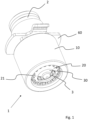
- Fig.1 shows in a perspective view an embodiment of a jet regulator 1, which is connected to a water connection 2.
- the water connection 2 can, for example, be part of a water dispenser or a machine for preparing drinks or the end piece of a water tap.
- Such outlets are usually tubular and emit a turbulent, inhomogeneous water jet, which, among other things, has a strong tendency to splash when it hits an adjacent surface.
- the task of the jet regulator 1 is to convert the escaping water into a visually appealing jet that is as circular and cylindrical as possible and which has only a slight tendency to splash when it hits a surface.
- the aim of the jet regulator 1 can be to reduce the flow rate when the tap is turned on via a throttle and thus contribute to saving water.
- the jet regulator 1 For attachment to the water connection 2, in this embodiment the jet regulator 1 comprises an upper part 60 which is designed as a handle with which the jet regulator 1 can be easily attached.
- the jet regulator 1 is completely, essentially circular-cylindrical and thus serves in particular to replace conventional aerators on a water tap.
- the jet regulator 1 has a sleeve-shaped outer contour.
- the sleeve comprises an outer sleeve 10 and an inner sleeve 20.
- a homogeneous water jet which has a laminar flow, leaves the jet regulator 1 via an annular channel 3.
- the annular channel 3 is formed between a coaxially arranged insert 30 with a conical head piece and a collar 21 which forms the front end wall of the inner sleeve 20.
- the collar 21 extends conically forwards, at least on the inside, preferably substantially parallel to the opposite wall of the insert 30 which is conically formed at the front.
- the ring channel 3 the end of which forms the outlet, is designed to taper conically towards the front.
- the total cross-section of the annular channel 3 decreases towards the front, which contributes to the generation of a laminar flow.
- Fig. 2 is a longitudinal section of the jet regulator 1 including water connection 2. This illustration shows all components of the jet regulator 1.
- the jet regulator 1 is connected to the water connection 2 by means of the upper part 60.
- the water enters an expansion chamber 6 via two flow paths.
- the jet regulator is designed such that the water enters the expansion chamber 6 via only one of the flow paths shown.
- Seal 4 is located between water connection 2 and upper part 60.
- an inlet piece 40 is arranged, which serves to guide the water into the expansion chamber 6.
- the upper part 60 and the inlet piece 40 can also be designed as a single component.
- the water flows through the inlet 7 through the jet regulator 1, which is designed as a sleeve, and leaves the jet regulator 1 at the outlet 3.
- the sleeve comprises an outer sleeve 10 and an inner sleeve 20.
- the outer sleeve 10 is connected to the upper part 60 via a thread 12.
- the components of the jet regulator 1 for jet shaping are arranged one after the other between the upper part 60 and a front collar 11 of the outer sleeve 10.
- the inner sleeve 20 rests with its front side on the collar 11 of the outer sleeve 10. Preferably, all of these components are inserted into the outer sleeve 10 without having to be welded or glued together.
- the outer sleeve 10 can be made of metal or plastic.
- the other components of the jet regulator 1, in particular the insert 30 and the inlet piece 40, are preferably designed as plastic injection-molded parts.
- the water flowing in from the inlet 7 is guided into the expansion chamber 6 via the inlet piece 40, whereby, particularly depending on the embodiment, two flow paths are possible, which, however, can also be combined with one another, as shown here.
- the expansion chamber 6 is designed as an annular channel which is arranged between the coaxial insert 30 and the sleeve, more precisely the inner sleeve 20.
- incoming water can enter the expansion chamber 6 via a side inlet 8.
- the inlet piece 40 can be designed with one or more edge-side openings so that water can flow into the expansion chamber 6 via a lateral inlet 8, which has a plurality of openings distributed around the circumference.
- This flow pattern is particularly suitable if no carbonated water is to be dispensed.
- the inlet piece 40 comprises a central channel 41, which is preferably aligned coaxially.
- the insert 30 is cup-shaped and comprises a blind hole 30 inside into which the central channel 41 leads.
- the central channel 41 projects into the blind hole 31, so that the interaction of the central channel 41 and the blind hole 31 creates a flow reversal which leads into the channel 5.
- the expansion chamber 6 is ring-shaped.
- the annular channel of the expansion chamber 6 then merges into a section up to the outlet 3 in which, due to the conical design of the insert 30 and the collar 21 which also runs conically towards the front, the diameter and thus also the total cross-sectional area of the annular channel gradually decreases up to the outlet 3.
- inlet 7 and outlet 3 there are no openings along the sleeve of the jet regulator 3 through which air can enter the water flow.
- the jet regulator 1 Due to the absence of grid-shaped inserts, the components of the jet regulator 1 have a relatively small surface area, which reduces undesirable germ formation.
- the jet regulator 1 is also suitable for dispensing hot water, cold water and carbonated water.
- the jet regulator 1 can be designed with a UV light source for killing germs.
- components of the jet regulator in particular the insert 30, the inner sleeve 20 and/or the inlet piece 40 can be made of a UV-permeable material, in particular of a UV-permeable plastic.
- the central channel 41 is provided on its upper side with a ring 50 which serves as a spacer.
- Fig.3 is a perspective view of the outer sleeve 10.
- the outer sleeve 10 comprises on its underside the collar 11, which serves as a stop for the inner sleeve (20).
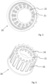
- Fig.5 is a perspective view of the inner sleeve 20, seen from the flow direction, i.e. from behind.
- the inner sleeve 20 is pot-shaped with a central opening in the bottom. Accordingly, the inner sleeve 20 comprises a front-side collar 21.
- the collar 21 On the inside, i.e. in the direction of the insert, the collar 21 comprises a plurality of spacers 22 which are distributed around the circumference of the collar and on which the insert (30) sits in the assembled state.
- the spacers 22 are designed as axially extending webs. This can improve the formation of a laminar flow.
- Fig.6 is a perspective view of the opposite side of the inner sleeve 20.
- the side wall of the inner sleeve 20 tapers obliquely, i.e. conically towards the front, in particular at an angle of 2 to 8° to the central axis.
- This design contributes to a successive slight reduction in the diameter of the expansion chamber towards the outlet, which improves the formation of a laminar flow.
- axially extending webs 23 are provided on the side wall.
- the webs 23 merge into the conical collar 21 via a transition web 24 at the front.
- This design has the function of a visually attractive technical appearance.
- an internal conical design of the collar 21 is sufficient for flow guidance, so that the area between the transition webs 24 can also be filled with material in another embodiment (not shown).
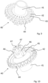
- Fig.7 is a perspective view of the insert 30, seen from behind, i.e. from the direction of the flow.
- the insert 30 comprises the blind hole 31 which is tapered at the front.
- the webs 33 are distributed around the circumference in the axial direction and serve to connect to the inlet piece.
- Fig.8 is a perspective view of the insert 30 from the side.
- the insert 30 is conical at the front and begins with a rounded head piece 34.
- the side wall of the insert 30 preferably extends at an angle of 30 to 60°, particularly preferably 40 to 50°, to the central axis.
- the transition region 35 is not exactly frustoconical, but comprises a recess 37 within which the angle of the side wall relative to the central axis changes.
- the angle of the side wall therefore becomes steeper towards the outlet, which improves the formation of a laminar flow.
- the transition area 35 merges into a fuselage section 36 via a rounded area 38.
- the fuselage piece 36 is slightly conical, in particular the side wall of the fuselage piece 36 is at an angle of 3 to 15° to the central axis.
- the conicity of the side wall of the body piece 36 can correspond to the inclination of the side wall of the inner sleeve in this area.
- Fig.9 is a perspective view of the inlet piece 40.
- the inlet piece 40 comprises a central channel 41 which opens into the insert (30).
- the inlet piece 40 is disk-shaped and includes the ring disk 42, which has channels 44 on the edge, through which part of the water can also reach the expansion chamber directly from the edge, without flowing over the insert. If this is not desired, the channels 44 can also be omitted (not shown).
- the annular disc 42 can be structured.
- a structure is provided by star-shaped webs 43.
- Fig.10 is a further perspective view of the inlet piece 40.
- the central channel 41 merges into a section with a coupling piece 45, which comprises axially extending grooves 46 and lateral recesses 47 at the front.
- Water can flow into the blind hole (31) of the insert via the edge recesses 47.
- This water then flows upwards (through channel 5) to the annular disc 42 and from there is introduced into the expansion chamber from the inside.
- the front wall of the annular disk 42 facing away from the flow i.e. the inner side, thickens towards the outside and thus, in cooperation with the opposite wall of the insert, forms a curved channel through which the water enters the expansion chamber.
- Fig. 11 is a perspective view of the ring 50, which serves as a spacer between the inlet piece and the Fig. 12 shown upper part 60.
- the upper part 60 includes the thread 62, via which the upper part 60 is connected to the outer sleeve.
- radially protruding handles 61 are provided, which facilitate screwing in the jet regulator.
- the invention made it possible to provide a jet regulator that is particularly suitable for carbonated and hot water.
- the jet regulator made it possible to provide a visually attractive jet with little tendency to splash in a surprisingly simple and efficient way.
Landscapes
- Health & Medical Sciences (AREA)
- Life Sciences & Earth Sciences (AREA)
- Engineering & Computer Science (AREA)
- Hydrology & Water Resources (AREA)
- Public Health (AREA)
- Water Supply & Treatment (AREA)
- Nozzles (AREA)
- Devices For Dispensing Beverages (AREA)
Claims (9)
- Régulateur de jet (1) pour la sortie d'un robinet ou d'un distributeur de boissons, comprenant une douille (20) ainsi qu'un insert (30) logé dans la douille (20), un canal circulaire (3) se trouvant entre l'insert (30) et la douille (20) et fournissant la sortie, et une chambre d'expansion (6) étant disposée entre une entrée (7) et le canal circulaire (3) et s'étendant autour de l'insert (30), caractérisé en ce que la surface de la section du canal circulaire (3), par rapport au sens d'écoulement, se réduit en aval de la chambre d'expansion (6) jusqu'à la sortie à une surface de section minimale, par le fait que le canal circulaire (3) présent entre la douille (20) et l'insert (30), qui forme d'abord la chambre d'expansion (6), se réduise en diamètre, et en ce que l'insert (30) présente une pièce supérieure (34) de forme conique, en face de laquelle se trouve un collet (21) de la douille (20), incliné en forme de cône et formant la face frontale de la douille (20).
- Régulateur de jet (1) selon la revendication 1, caractérisé en ce que l'entrée (7) est conçue comme un étranglement de débit, en particulier en ce que l'entrée (7) passe par un canal circulaire entre la douille (20) et une pièce d'afflux (40) et/ou par un canal central (41) qui mène à un canal circulaire opposé par rapport au sens d'écoulement et s'étendant vers le haut entre le canal central (41) et l'insert (30).
- Régulateur de jet (1) selon l'une des revendications précédentes, caractérisé en ce que la sortie comprend un anneau avec des entretoises (22) s'étendant axialement pour l'insert (30).
- Régulateur de jet (1) selon l'une des revendications précédentes, caractérisé en ce que la sortie est formée par le canal circulaire (3) qui s'étend entre une extrémité avant de l'insert et la douille (20) conçue sous forme de douille intérieure.
- Régulateur de jet (1) selon l'une des revendications précédentes, caractériséen ce que la douille (20) présente un diamètre de 10 à 40 mm, de préférence de 15 à 25 mm,et/ou en ce que le régulateur de jet (1) comprend une source de lumière UV,et/ou en ce que le régulateur de jet (1) est dimensionné de telle sorte que, pour une pression de 6 bars appliquée à l'entrée (7), pour de l'eau à 20 °C, de l'eau à 20 °C avec 6 g/l de gaz carbonique et de l'eau à 60 °C (dans des conditions standard), le nombre de Reynolds Re de l'eau qui s'écoule est inférieur à 2300, de préférence inférieur à 2000,et/ou en ce que la douille (20) conçue sous forme de douille intérieure comprend, côté sortie, le collet (21) conique.
- Régulateur de jet (1) selon l'une des revendications précédentes, caractérisé en ce qu'un canal central (41) comprend, côté entrée, un collet s'étendant radialement vers l'extérieur, en particulier un collet qui forme un canal circulaire entre la douille et le collet, en particulier un collet conique vers l'avant.
- Régulateur de jet (1) selon l'une des revendications précédentes, caractérisé en ce que l'entrée (7) est reliée à la chambre d'expansion (6) par une inversion de flux.
- Utilisation d'un régulateur de jet (1) selon l'une des revendications précédentes pour un distributeur d'eau ou une machine pour la préparation de boissons, en particulier de boissons chaudes et froides.
- Robinet et/ou distributeur d'eau et/ou machine pour la préparation de boissons, comprenant un régulateur de jet (1) selon l'une des revendications 1 à 7.
Applications Claiming Priority (2)
| Application Number | Priority Date | Filing Date | Title |
|---|---|---|---|
| DE102020129021.7A DE102020129021A1 (de) | 2020-11-04 | 2020-11-04 | Strahlregler |
| PCT/EP2021/080476 WO2022096488A1 (fr) | 2020-11-04 | 2021-11-03 | Brise-jet |
Publications (2)
| Publication Number | Publication Date |
|---|---|
| EP4240919A1 EP4240919A1 (fr) | 2023-09-13 |
| EP4240919B1 true EP4240919B1 (fr) | 2024-09-25 |
Family
ID=78592854
Family Applications (1)
| Application Number | Title | Priority Date | Filing Date |
|---|---|---|---|
| EP21805927.7A Active EP4240919B1 (fr) | 2020-11-04 | 2021-11-03 | Brise-jet |
Country Status (4)
| Country | Link |
|---|---|
| US (1) | US12448761B2 (fr) |
| EP (1) | EP4240919B1 (fr) |
| DE (1) | DE102020129021A1 (fr) |
| WO (1) | WO2022096488A1 (fr) |
Families Citing this family (1)
| Publication number | Priority date | Publication date | Assignee | Title |
|---|---|---|---|---|
| DE102020129021A1 (de) * | 2020-11-04 | 2022-05-05 | Bwt Holding Gmbh | Strahlregler |
Family Cites Families (20)
| Publication number | Priority date | Publication date | Assignee | Title |
|---|---|---|---|---|
| US2811340A (en) * | 1949-12-29 | 1957-10-29 | Elie P Aghnides | Fluid mixing device |
| US2832643A (en) | 1954-02-15 | 1958-04-29 | Ralph E Bletcher | Flow regulator |
| US3286935A (en) * | 1965-02-08 | 1966-11-22 | Standard Screw | Combined liquid spray and aerator |
| US3884418A (en) * | 1974-08-30 | 1975-05-20 | Cranda Corp | Aerating and spraying attachment for faucets |
| US4221337A (en) | 1979-01-17 | 1980-09-09 | Shames Sidney J | Aerator and spray combination |
| US5348231A (en) * | 1993-10-05 | 1994-09-20 | Arnold Don C | Two-stage aerator |
| US5549822A (en) | 1995-01-13 | 1996-08-27 | Ferguson; George E. | Shower filter apparatus |
| DE20022166U1 (de) | 2000-12-20 | 2001-06-21 | Huthmann, André, 27632 Midlum | Vorrichtung zum Regeln der Durchflußmenge eines fluiden Mediums |
| ITRM20060232A1 (it) * | 2006-04-28 | 2007-10-29 | Blue Magic S R L | Dispositivo erogatore per impianti idraulici |
| US7581685B2 (en) | 2007-07-19 | 2009-09-01 | Christian Belisle | Faucet end piece |
| DE102010007871B4 (de) | 2010-02-13 | 2015-02-05 | Neoperl Gmbh | Strahlregler |
| US9421561B2 (en) * | 2014-03-31 | 2016-08-23 | Toto Ltd. | Water spouting device |
| DE102014006216A1 (de) | 2014-04-30 | 2015-11-05 | Neoperl Gmbh | Strahlregler |
| DE202014003568U1 (de) * | 2014-04-30 | 2015-07-31 | Neoperl Gmbh | Strahlregler |
| DE202015000856U1 (de) * | 2015-02-03 | 2016-05-04 | Neoperl Gmbh | Sanitäres Auslaufelement |
| DE102015002740A1 (de) | 2015-03-05 | 2016-09-08 | Neoperl Gmbh | Strahlregler |
| CN204781152U (zh) | 2015-06-02 | 2015-11-18 | 厦门水蜻蜓卫浴科技有限公司 | 出水控制装置 |
| CN204852457U (zh) * | 2015-08-07 | 2015-12-09 | 恺霖卫浴科技(厦门)有限公司 | 一种双流量切换装置 |
| CN106703132B (zh) * | 2015-11-13 | 2019-09-27 | 厦门松霖科技股份有限公司 | 恒流起泡器 |
| DE102020129021A1 (de) * | 2020-11-04 | 2022-05-05 | Bwt Holding Gmbh | Strahlregler |
-
2020
- 2020-11-04 DE DE102020129021.7A patent/DE102020129021A1/de active Pending
-
2021
- 2021-11-03 US US18/035,076 patent/US12448761B2/en active Active
- 2021-11-03 EP EP21805927.7A patent/EP4240919B1/fr active Active
- 2021-11-03 WO PCT/EP2021/080476 patent/WO2022096488A1/fr not_active Ceased
Also Published As
| Publication number | Publication date |
|---|---|
| US20230332388A1 (en) | 2023-10-19 |
| DE102020129021A1 (de) | 2022-05-05 |
| WO2022096488A1 (fr) | 2022-05-12 |
| US12448761B2 (en) | 2025-10-21 |
| EP4240919A1 (fr) | 2023-09-13 |
Similar Documents
| Publication | Publication Date | Title |
|---|---|---|
| EP1312292B1 (fr) | Dispositif de moussage de lait et de chauffage de lait | |
| EP2178624B1 (fr) | Dispositif pour enrichir un courant de liquide avec un gaz | |
| DE10027986B4 (de) | Sanitäres Einbauteil | |
| EP1870003B1 (fr) | Dispositif pour émulsifier du lait | |
| DE112012005017B4 (de) | Vorrichtung zum Steuern einer Fluid-Strömung in einem Notfall-Waschsystem, Vorrichtung zum Steuern einer Fluid-Strömung und Waschsystem zum Liefern einer Fluid-Strömung | |
| EP3360844B1 (fr) | Installation de débit, robinet correspondant ainsi que procédé de production de café ou de bière azotés | |
| EP2606782A1 (fr) | Machine à café/espresso dotée d´un dispositif de production de mousse de lait pour cappuccino | |
| EP3457901B1 (fr) | Dispositif de sortie pour un dispositif de mousse de lait | |
| EP2331755B1 (fr) | Dispositif de régulation pour orifice d'écoulement d'eau, en particulier d'une plomberie sanitaire | |
| EP3757301A1 (fr) | Régulateur de jet | |
| EP1787554B1 (fr) | Dispositif pour émulsifier | |
| EP2944237A1 (fr) | Dispositif d'écoulement pour un dispositif de mousse de lait | |
| DE10394030T5 (de) | Fluidsteuervorrichtung | |
| DE60200085T2 (de) | Zapfhahn | |
| DE102009021410A1 (de) | Strahlregler sowie sanitärer Wasserauslauf | |
| DE3706694C2 (fr) | ||
| EP4240919B1 (fr) | Brise-jet | |
| EP1952046B2 (fr) | Soupape a double siege | |
| DE19841401C2 (de) | Zweistoff-Flachstrahldüse | |
| DE102006048456A1 (de) | Imprägnierer-Einlass | |
| EP2703336B1 (fr) | Robinet mélangeur pour une installation de distribution de boissons | |
| DE10138622A1 (de) | Zerstäuber zum Vernebeln einer Flüssigkeit | |
| EP1235979A2 (fr) | Dispositif pour acheminer un combustible de preference liquide ou gazeux dans une chambre de combustion | |
| DE102004051258A1 (de) | Armatur mit austretendem hohlen Strahl | |
| DE202022101670U1 (de) | Auslaufarmatur mit Strömungsleitkörper |
Legal Events
| Date | Code | Title | Description |
|---|---|---|---|
| STAA | Information on the status of an ep patent application or granted ep patent |
Free format text: STATUS: UNKNOWN |
|
| STAA | Information on the status of an ep patent application or granted ep patent |
Free format text: STATUS: THE INTERNATIONAL PUBLICATION HAS BEEN MADE |
|
| PUAI | Public reference made under article 153(3) epc to a published international application that has entered the european phase |
Free format text: ORIGINAL CODE: 0009012 |
|
| STAA | Information on the status of an ep patent application or granted ep patent |
Free format text: STATUS: REQUEST FOR EXAMINATION WAS MADE |
|
| 17P | Request for examination filed |
Effective date: 20230524 |
|
| AK | Designated contracting states |
Kind code of ref document: A1 Designated state(s): AL AT BE BG CH CY CZ DE DK EE ES FI FR GB GR HR HU IE IS IT LI LT LU LV MC MK MT NL NO PL PT RO RS SE SI SK SM TR |
|
| DAV | Request for validation of the european patent (deleted) | ||
| DAX | Request for extension of the european patent (deleted) | ||
| GRAP | Despatch of communication of intention to grant a patent |
Free format text: ORIGINAL CODE: EPIDOSNIGR1 |
|
| STAA | Information on the status of an ep patent application or granted ep patent |
Free format text: STATUS: GRANT OF PATENT IS INTENDED |
|
| GRAS | Grant fee paid |
Free format text: ORIGINAL CODE: EPIDOSNIGR3 |
|
| INTG | Intention to grant announced |
Effective date: 20240715 |
|
| GRAA | (expected) grant |
Free format text: ORIGINAL CODE: 0009210 |
|
| STAA | Information on the status of an ep patent application or granted ep patent |
Free format text: STATUS: THE PATENT HAS BEEN GRANTED |
|
| AK | Designated contracting states |
Kind code of ref document: B1 Designated state(s): AL AT BE BG CH CY CZ DE DK EE ES FI FR GB GR HR HU IE IS IT LI LT LU LV MC MK MT NL NO PL PT RO RS SE SI SK SM TR |
|
| REG | Reference to a national code |
Ref country code: GB Ref legal event code: FG4D Free format text: NOT ENGLISH |
|
| REG | Reference to a national code |
Ref country code: CH Ref legal event code: EP |
|
| P01 | Opt-out of the competence of the unified patent court (upc) registered |
Free format text: CASE NUMBER: APP_49891/2024 Effective date: 20240903 |
|
| REG | Reference to a national code |
Ref country code: DE Ref legal event code: R096 Ref document number: 502021005273 Country of ref document: DE |
|
| REG | Reference to a national code |
Ref country code: IE Ref legal event code: FG4D Free format text: LANGUAGE OF EP DOCUMENT: GERMAN |
|
| REG | Reference to a national code |
Ref country code: LT Ref legal event code: MG9D |
|
| PG25 | Lapsed in a contracting state [announced via postgrant information from national office to epo] |
Ref country code: NO Free format text: LAPSE BECAUSE OF FAILURE TO SUBMIT A TRANSLATION OF THE DESCRIPTION OR TO PAY THE FEE WITHIN THE PRESCRIBED TIME-LIMIT Effective date: 20241225 |
|
| PG25 | Lapsed in a contracting state [announced via postgrant information from national office to epo] |
Ref country code: GR Free format text: LAPSE BECAUSE OF FAILURE TO SUBMIT A TRANSLATION OF THE DESCRIPTION OR TO PAY THE FEE WITHIN THE PRESCRIBED TIME-LIMIT Effective date: 20241226 Ref country code: FI Free format text: LAPSE BECAUSE OF FAILURE TO SUBMIT A TRANSLATION OF THE DESCRIPTION OR TO PAY THE FEE WITHIN THE PRESCRIBED TIME-LIMIT Effective date: 20240925 |
|
| PG25 | Lapsed in a contracting state [announced via postgrant information from national office to epo] |
Ref country code: BG Free format text: LAPSE BECAUSE OF FAILURE TO SUBMIT A TRANSLATION OF THE DESCRIPTION OR TO PAY THE FEE WITHIN THE PRESCRIBED TIME-LIMIT Effective date: 20240925 |
|
| PG25 | Lapsed in a contracting state [announced via postgrant information from national office to epo] |
Ref country code: LV Free format text: LAPSE BECAUSE OF FAILURE TO SUBMIT A TRANSLATION OF THE DESCRIPTION OR TO PAY THE FEE WITHIN THE PRESCRIBED TIME-LIMIT Effective date: 20240925 |
|
| PG25 | Lapsed in a contracting state [announced via postgrant information from national office to epo] |
Ref country code: RS Free format text: LAPSE BECAUSE OF FAILURE TO SUBMIT A TRANSLATION OF THE DESCRIPTION OR TO PAY THE FEE WITHIN THE PRESCRIBED TIME-LIMIT Effective date: 20241225 |
|
| REG | Reference to a national code |
Ref country code: NL Ref legal event code: MP Effective date: 20240925 |
|
| PG25 | Lapsed in a contracting state [announced via postgrant information from national office to epo] |
Ref country code: RS Free format text: LAPSE BECAUSE OF FAILURE TO SUBMIT A TRANSLATION OF THE DESCRIPTION OR TO PAY THE FEE WITHIN THE PRESCRIBED TIME-LIMIT Effective date: 20241225 Ref country code: NO Free format text: LAPSE BECAUSE OF FAILURE TO SUBMIT A TRANSLATION OF THE DESCRIPTION OR TO PAY THE FEE WITHIN THE PRESCRIBED TIME-LIMIT Effective date: 20241225 Ref country code: LV Free format text: LAPSE BECAUSE OF FAILURE TO SUBMIT A TRANSLATION OF THE DESCRIPTION OR TO PAY THE FEE WITHIN THE PRESCRIBED TIME-LIMIT Effective date: 20240925 Ref country code: GR Free format text: LAPSE BECAUSE OF FAILURE TO SUBMIT A TRANSLATION OF THE DESCRIPTION OR TO PAY THE FEE WITHIN THE PRESCRIBED TIME-LIMIT Effective date: 20241226 Ref country code: FI Free format text: LAPSE BECAUSE OF FAILURE TO SUBMIT A TRANSLATION OF THE DESCRIPTION OR TO PAY THE FEE WITHIN THE PRESCRIBED TIME-LIMIT Effective date: 20240925 Ref country code: BG Free format text: LAPSE BECAUSE OF FAILURE TO SUBMIT A TRANSLATION OF THE DESCRIPTION OR TO PAY THE FEE WITHIN THE PRESCRIBED TIME-LIMIT Effective date: 20240925 |
|
| PG25 | Lapsed in a contracting state [announced via postgrant information from national office to epo] |
Ref country code: NL Free format text: LAPSE BECAUSE OF FAILURE TO SUBMIT A TRANSLATION OF THE DESCRIPTION OR TO PAY THE FEE WITHIN THE PRESCRIBED TIME-LIMIT Effective date: 20240925 |
|
| PG25 | Lapsed in a contracting state [announced via postgrant information from national office to epo] |
Ref country code: IS Free format text: LAPSE BECAUSE OF FAILURE TO SUBMIT A TRANSLATION OF THE DESCRIPTION OR TO PAY THE FEE WITHIN THE PRESCRIBED TIME-LIMIT Effective date: 20250125 Ref country code: PT Free format text: LAPSE BECAUSE OF FAILURE TO SUBMIT A TRANSLATION OF THE DESCRIPTION OR TO PAY THE FEE WITHIN THE PRESCRIBED TIME-LIMIT Effective date: 20250127 |
|
| PG25 | Lapsed in a contracting state [announced via postgrant information from national office to epo] |
Ref country code: RO Free format text: LAPSE BECAUSE OF FAILURE TO SUBMIT A TRANSLATION OF THE DESCRIPTION OR TO PAY THE FEE WITHIN THE PRESCRIBED TIME-LIMIT Effective date: 20240925 Ref country code: SM Free format text: LAPSE BECAUSE OF FAILURE TO SUBMIT A TRANSLATION OF THE DESCRIPTION OR TO PAY THE FEE WITHIN THE PRESCRIBED TIME-LIMIT Effective date: 20240925 |
|
| PG25 | Lapsed in a contracting state [announced via postgrant information from national office to epo] |
Ref country code: ES Free format text: LAPSE BECAUSE OF FAILURE TO SUBMIT A TRANSLATION OF THE DESCRIPTION OR TO PAY THE FEE WITHIN THE PRESCRIBED TIME-LIMIT Effective date: 20240925 |
|
| PG25 | Lapsed in a contracting state [announced via postgrant information from national office to epo] |
Ref country code: EE Free format text: LAPSE BECAUSE OF FAILURE TO SUBMIT A TRANSLATION OF THE DESCRIPTION OR TO PAY THE FEE WITHIN THE PRESCRIBED TIME-LIMIT Effective date: 20240925 |
|
| PG25 | Lapsed in a contracting state [announced via postgrant information from national office to epo] |
Ref country code: PL Free format text: LAPSE BECAUSE OF FAILURE TO SUBMIT A TRANSLATION OF THE DESCRIPTION OR TO PAY THE FEE WITHIN THE PRESCRIBED TIME-LIMIT Effective date: 20240925 Ref country code: CZ Free format text: LAPSE BECAUSE OF FAILURE TO SUBMIT A TRANSLATION OF THE DESCRIPTION OR TO PAY THE FEE WITHIN THE PRESCRIBED TIME-LIMIT Effective date: 20240925 |
|
| PG25 | Lapsed in a contracting state [announced via postgrant information from national office to epo] |
Ref country code: IT Free format text: LAPSE BECAUSE OF FAILURE TO SUBMIT A TRANSLATION OF THE DESCRIPTION OR TO PAY THE FEE WITHIN THE PRESCRIBED TIME-LIMIT Effective date: 20240925 Ref country code: SK Free format text: LAPSE BECAUSE OF FAILURE TO SUBMIT A TRANSLATION OF THE DESCRIPTION OR TO PAY THE FEE WITHIN THE PRESCRIBED TIME-LIMIT Effective date: 20240925 |
|
| REG | Reference to a national code |
Ref country code: DE Ref legal event code: R097 Ref document number: 502021005273 Country of ref document: DE |
|
| PG25 | Lapsed in a contracting state [announced via postgrant information from national office to epo] |
Ref country code: MC Free format text: LAPSE BECAUSE OF FAILURE TO SUBMIT A TRANSLATION OF THE DESCRIPTION OR TO PAY THE FEE WITHIN THE PRESCRIBED TIME-LIMIT Effective date: 20240925 |
|
| PG25 | Lapsed in a contracting state [announced via postgrant information from national office to epo] |
Ref country code: DK Free format text: LAPSE BECAUSE OF FAILURE TO SUBMIT A TRANSLATION OF THE DESCRIPTION OR TO PAY THE FEE WITHIN THE PRESCRIBED TIME-LIMIT Effective date: 20240925 |
|
| PG25 | Lapsed in a contracting state [announced via postgrant information from national office to epo] |
Ref country code: LU Free format text: LAPSE BECAUSE OF NON-PAYMENT OF DUE FEES Effective date: 20241103 |
|
| PLBE | No opposition filed within time limit |
Free format text: ORIGINAL CODE: 0009261 |
|
| STAA | Information on the status of an ep patent application or granted ep patent |
Free format text: STATUS: NO OPPOSITION FILED WITHIN TIME LIMIT |
|
| REG | Reference to a national code |
Ref country code: BE Ref legal event code: MM Effective date: 20241130 |
|
| 26N | No opposition filed |
Effective date: 20250626 |
|
| PG25 | Lapsed in a contracting state [announced via postgrant information from national office to epo] |
Ref country code: SE Free format text: LAPSE BECAUSE OF FAILURE TO SUBMIT A TRANSLATION OF THE DESCRIPTION OR TO PAY THE FEE WITHIN THE PRESCRIBED TIME-LIMIT Effective date: 20240925 |
|
| PG25 | Lapsed in a contracting state [announced via postgrant information from national office to epo] |
Ref country code: BE Free format text: LAPSE BECAUSE OF NON-PAYMENT OF DUE FEES Effective date: 20241130 |
|
| PG25 | Lapsed in a contracting state [announced via postgrant information from national office to epo] |
Ref country code: FR Free format text: LAPSE BECAUSE OF NON-PAYMENT OF DUE FEES Effective date: 20241125 |
|
| PG25 | Lapsed in a contracting state [announced via postgrant information from national office to epo] |
Ref country code: IE Free format text: LAPSE BECAUSE OF NON-PAYMENT OF DUE FEES Effective date: 20241103 |
|
| REG | Reference to a national code |
Ref country code: CH Ref legal event code: U11 Free format text: ST27 STATUS EVENT CODE: U-0-0-U10-U11 (AS PROVIDED BY THE NATIONAL OFFICE) Effective date: 20251201 |
|
| PGFP | Annual fee paid to national office [announced via postgrant information from national office to epo] |
Ref country code: DE Payment date: 20251118 Year of fee payment: 5 |
|
| PGFP | Annual fee paid to national office [announced via postgrant information from national office to epo] |
Ref country code: AT Payment date: 20260113 Year of fee payment: 5 |
|
| PG25 | Lapsed in a contracting state [announced via postgrant information from national office to epo] |
Ref country code: HR Free format text: LAPSE BECAUSE OF FAILURE TO SUBMIT A TRANSLATION OF THE DESCRIPTION OR TO PAY THE FEE WITHIN THE PRESCRIBED TIME-LIMIT Effective date: 20240925 |
|
| PGFP | Annual fee paid to national office [announced via postgrant information from national office to epo] |
Ref country code: CH Payment date: 20251201 Year of fee payment: 5 |
|
| PG25 | Lapsed in a contracting state [announced via postgrant information from national office to epo] |
Ref country code: HU Free format text: LAPSE BECAUSE OF FAILURE TO SUBMIT A TRANSLATION OF THE DESCRIPTION OR TO PAY THE FEE WITHIN THE PRESCRIBED TIME-LIMIT; INVALID AB INITIO Effective date: 20211103 |
|
| PG25 | Lapsed in a contracting state [announced via postgrant information from national office to epo] |
Ref country code: CY Free format text: LAPSE BECAUSE OF FAILURE TO SUBMIT A TRANSLATION OF THE DESCRIPTION OR TO PAY THE FEE WITHIN THE PRESCRIBED TIME-LIMIT; INVALID AB INITIO Effective date: 20211103 |