EP4241621A2 - Höhenverstellbarer hocker - Google Patents
Höhenverstellbarer hocker Download PDFInfo
- Publication number
- EP4241621A2 EP4241621A2 EP23152605.4A EP23152605A EP4241621A2 EP 4241621 A2 EP4241621 A2 EP 4241621A2 EP 23152605 A EP23152605 A EP 23152605A EP 4241621 A2 EP4241621 A2 EP 4241621A2
- Authority
- EP
- European Patent Office
- Prior art keywords
- outer tube
- inner tube
- foot
- locking
- seat part
- Prior art date
- Legal status (The legal status is an assumption and is not a legal conclusion. Google has not performed a legal analysis and makes no representation as to the accuracy of the status listed.)
- Granted
Links
Images

Classifications
-
- A—HUMAN NECESSITIES
- A47—FURNITURE; DOMESTIC ARTICLES OR APPLIANCES; COFFEE MILLS; SPICE MILLS; SUCTION CLEANERS IN GENERAL
- A47C—CHAIRS; SOFAS; BEDS
- A47C3/00—Chairs characterised by structural features; Chairs or stools with rotatable or vertically-adjustable seats
- A47C3/20—Chairs or stools with vertically-adjustable seats
- A47C3/28—Chairs or stools with vertically-adjustable seats with clamps acting on vertical rods
- A47C3/285—Chairs or stools with vertically-adjustable seats with clamps acting on vertical rods with radially expansible clamping elements telescopically engaged in a tube or the like
-
- A—HUMAN NECESSITIES
- A47—FURNITURE; DOMESTIC ARTICLES OR APPLIANCES; COFFEE MILLS; SPICE MILLS; SUCTION CLEANERS IN GENERAL
- A47C—CHAIRS; SOFAS; BEDS
- A47C3/00—Chairs characterised by structural features; Chairs or stools with rotatable or vertically-adjustable seats
- A47C3/20—Chairs or stools with vertically-adjustable seats
- A47C3/34—Chairs or stools with vertically-adjustable seats with pins coacting with holes
-
- A—HUMAN NECESSITIES
- A47—FURNITURE; DOMESTIC ARTICLES OR APPLIANCES; COFFEE MILLS; SPICE MILLS; SUCTION CLEANERS IN GENERAL
- A47C—CHAIRS; SOFAS; BEDS
- A47C3/00—Chairs characterised by structural features; Chairs or stools with rotatable or vertically-adjustable seats
- A47C3/20—Chairs or stools with vertically-adjustable seats
- A47C3/40—Telescopic guides
-
- A—HUMAN NECESSITIES
- A47—FURNITURE; DOMESTIC ARTICLES OR APPLIANCES; COFFEE MILLS; SPICE MILLS; SUCTION CLEANERS IN GENERAL
- A47C—CHAIRS; SOFAS; BEDS
- A47C9/00—Stools for specified purposes
Definitions
- the invention relates to a height-adjustable stool according to the preamble of claim 1.
- Such stools are mainly used in the office and are intended to allow you to sit at your desk without straining your back.
- Stools of the type mentioned at the beginning are known, which have a gas spring to adapt their height to the size of the user, with which the length of the connecting part between the foot and the seat part can be varied.
- this height adjustment is limited to a few centimeters, so adjusting the height of the stool for sitting at a height-adjustable desk is usually not enough.
- height-adjustable stools are known, the height of which can be adjusted within a significantly larger range.
- the inner tube which is slidably guided in the outer tube, is provided with circumferential grooves at constant intervals, into which a locking element mounted on the outer tube can engage, which is axially displaceable between a locking position and a release position.
- the locking element has an inwardly projecting, all-round rib, which in the locking position engages in the corresponding groove of the inner tube, and which comes out of engagement with the groove by moving the locking element against a restoring force into the release position.
- the last-mentioned stools have the disadvantage that, due to incorrect operation, there is a risk that the user will suddenly and unbrakedly slide down from the top seating position to the bottom seating position if the lock is accidentally released.
- the invention is based on the idea that the locking mechanism is difficult to release when a person sits on the seat and loads it with a significant part of their weight.
- a great deal of force is required, which is rarely applied unintentionally.
- the hook has a locking surface facing away from the second lever arm, which is inclined obliquely radially inwards in a direction away from the end of the inner tube protruding from the outer tube when the hook engages in one of the engagement openings.
- the hook expediently has a run-up slope facing away from the locking surface, which, when the hook engages in one of the engagement openings, is preferably inclined to the horizontal at a larger angle than the locking surface. This measure enables the height of the stool to be increased by pulling the inner tube out of the outer tube without necessarily having to release the lock by operating the second lever arm. If a user stands on the foot of the stool and pulls up on the seat part, the force of the edge of the relevant engagement opening acting on the ramp may be sufficient to release the lock.
- the locking mechanism expediently has a further locking lever which is identical to the locking lever, and the inner tube has further engagement openings whose number and arrangement correspond to the engagement openings. This measure strengthens the locking and further minimizes the risk of accidental actuation of the locking mechanism to release the locking, since both locking levers must be actuated for this purpose. It is preferred that the locking lever and the further locking lever on the one hand and the engagement openings and the further engagement openings on the other hand are each diametrically opposed in pairs. Furthermore, it is preferred that the locking lever and the further locking lever can be pivoted independently of one another about their respective pivot axis, i.e. are not coupled in their movement, so that the cancellation of the locking by one of the two locking levers does not cause the cancellation of the locking by the other locking lever .
- the second lever arm of the locking lever and possibly the further locking lever is expediently longer than the first lever arm.
- a user then has to carry out a fairly large pivoting movement of the second lever arm in order to move the hook out of the engagement opening, so that the risk of unintentional incorrect operation is further reduced.
- the inner tube and the outer tube each have a circular cross section.
- a positioning element projects radially from the inner tube, which is displaceably received in a groove running in the axial direction on the inside of the outer tube is.
- the channel can also end at an upper and a lower stop surface for the positioning element, so that it can only be moved to a limited extent. Through this measure This prevents the inner tube from being pulled out undesirably from the outer tube.
- the inner tube is connected to a sleeve, which rests on the inside of the outer ear to form a frictional connection. Due to the frictional connection, the sleeve acts as a kind of brake, which prevents the foot from falling uncontrollably when the seat part is lifted and the locking mechanism is released.
- the frictional connection counteracts such an uncontrolled falling with a frictional force, which can easily be overcome by pressing down the foot and pulling up the seat part.
- the positioning element is a pin arranged on the sleeve.
- the sleeve expediently has a shoulder protruding from the end of the inner tube received in the outer tube and resting on the inside of the outer tube. It is preferred that the inner tube is held at a distance from the inside of the outer tube over its entire length by means of the shoulder and a guide element arranged on the end of the outer tube facing the seat part. When the inner tube is moved relative to the outer tube, the two tubes do not rub against each other.
- the sleeve is expediently made of plastic, at least in the area of the heel.
- the frictional connection is expediently produced by means of at least one friction element which is pressed against the inside of the outer tube by means of an elastic force and with which the sleeve is provided.
- the friction element can be a ring made of an elastomeric material that runs around the sleeve.
- two diametrically opposed friction elements to be accommodated in the sleeve, each of which passes through a hole in the inner tube and is pressed away from each other onto the inside of the outer tube by means of a spring.
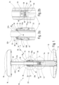
- the stool 10 shown in the drawing has a foot 12 with a convexly curved base 14 on the bottom for placing on a floor and a seat part 16 with a seat 18 on the top.
- the foot 12 and the seat part 16 are connected to one another by means of a connecting part 20, which has an outer tube 22 which is fixedly connected to the foot 12 and an inner tube 24 which is fixedly connected to the seat part 16 and which is accommodated in the inner tube 22 in a longitudinally displaceable manner and has an upper end 26 protrudes from the outer tube 22.
- the outer tube 22 and the inner tube 24 each have a circular cross section.
- the seat part 16 can be arranged at different heights relative to the foot 12 by moving the inner tube 24 with respect to the outer tube 22 by locking the inner tube 24 in a number of different positions with respect to the outer tube 22 by means of a locking mechanism 28.
- the locking mechanism 28 has a locking lever 30a and a further locking lever 30b diametrically opposite the locking lever 30a, each of which is pivotally articulated on the outer tube 22 about a pivot axis 32.
- the locking lever 30a and the further locking lever 30b are identical in construction and each have a first lever arm 34 which extends upwards from the pivot axis 32 and has a hook 38 at its free end 36, and one which extends downwards from the pivot axis 32 and
- the second lever arm 40 protrudes obliquely from the outer tube 22 and is longer than the first lever arm 34.
- the inner tube 24 has an axially extending row of engagement openings 42a arranged at equal distances from one another, into which the hook 38 of the locking lever 30a engages to fix the inner tube 24 on the outer tube 22.
- Diametrically opposite each of the engagement openings 42a is a further engagement opening 42b, into which the hook 38 of the further locking lever 30b engages.
- the first lever arm 34 of the locking lever 30a and the further locking lever 30b each projects obliquely inwards, while the second lever arm 40 protrudes obliquely outwards from the outer tube 22.
- the hooks 38 each have a locking surface 44 on their upper side facing away from the respective pivot axis 32, which is inclined radially inwards and downwards when engaging in one of the engagement openings 42a or one of the further engagement openings 42b.
- the hooks 38 Facing away from the locking surface 44, the hooks 38 each have a ramp 46, which is inclined radially inwards and upwards when the respective hook 38 engages in one of the engagement openings 42a or in one of the further engagement openings 42b, with its angle of inclination relative to the horizontal then is greater than the angle of inclination of the opposite locking surface 44 with respect to the horizontal.
- a sleeve 50 is arranged, which is received in the inner tube 24 over the majority of its length. While the outer tube 22 and the inner tube 24 are made of metal, the sleeve 50 has a base body made of plastic. It has a shoulder 52 protruding from the lower end 48 of the inner tube 24, which also has a circular cross section, but whose diameter is larger than the outer diameter of the inner tube 24 and, minus a small amount of play, corresponds to the inner diameter of the outer tube 22, so that he on the inside 54 of which rests.
- the sleeve 50 also has two pin-shaped friction elements 58 which extend through diametrically opposite holes 60 in the inner tube 24 and rest on the inside 54 of the outer tube 22.
- a compression spring 62 designed as a helical spring is arranged between the two friction elements 58 and presses the friction elements 58 away from one another against the inside 54 of the outer tube 22 in order to produce a frictional connection.
- a pin-shaped positioning element 64 protrudes radially from the sleeve 50, which engages in a groove in the outer tube 22 (not shown in the drawing), so that the inner tube 24 is accommodated in the outer tube 22 in a rotationally fixed manner.
- the groove is secured at the top and bottom by a stop surface limited, so that the positioning element 64 can only be displaced to a limited extent between the stop surfaces and prevents the inner tube 24 from being completely pulled out of the outer tube 22.
- the invention relates to a height-adjustable stool 10 with a foot 12 for placing on a floor, with a seat part 16 having an upper seat surface 18 and with a connecting part 20 connecting the foot 12 and the seat part 16, the connecting part 20 being a Outer tube 22 and an inner tube 24 displaceably accommodated in the outer tube 22, with either the outer tube 22 fixed to the foot 12 and the inner tube 24 fixed to the seat part 16 or the outer tube 22 fixed to the seat part 16 and the inner tube 24 fixed to the foot 12 is connected, and with a locking mechanism 28 for releasably locking the inner tube 24 on the outer tube 22 in several positions defining different distances of the seat part 16 from the foot 12.
- the locking mechanism 28 has a two-armed locking lever 30a which is pivotable about a pivot axis 32 on the outer tube 22 and which has a hook 38 at the free end 36 of its first lever arm 34 and whose second lever arm 40 projects obliquely outwards from the pivot axis 32 and can be pivoted radially inwards against the force of a return spring, and that the inner tube 24 has a number of engagement openings 42a for the hook 38 arranged at a distance from one another in a row. Additionally or alternatively, it is provided according to the invention that the inner tube 24 is connected to a sleeve 50, which rests on the inside 54 of the outer tube 22 to form a frictional connection.
Landscapes
- Toilet Supplies (AREA)
- Special Chairs (AREA)
- Mutual Connection Of Rods And Tubes (AREA)
Abstract
Description
- Die Erfindung betrifft einen höhenverstellbaren Hocker gemäß Oberbegriff des Anspruchs 1.
- Solche Hocker werden überwiegend im Büro eingesetzt und sollen ein rückenschonendes Sitzen am Schreibtisch ermöglichen. Dabei sind Hocker der eingangs genannten Art bekannt, die zur Anpassung ihrer Höhe an die Größe des Benutzers eine Gasfeder aufweisen, mit der die Länge des Verbindungsteils zwischen dem Fuß und dem Sitzteil variiert werden kann. Diese Höhenverstellung ist aber auf einige Zentimeter begrenzt, so dass die Anpassung der Höhe des Hockers zum Sitzen an einem höhenverstellbaren Schreibtisch in der Regel nicht ausreicht. Des Weiteren sind höhenverstellbare Hocker bekannt, deren Höhe innerhalb einer deutlichen größeren Spanne verstellbar ist. Bei diesen Hockern ist das im Außenrohr verschiebbar geführte Innenrohr in konstanten Abständen mit umlaufenden Rillen versehen, in die ein am Außenrohr montiertes Arretierelement eingreifen kann, welches zwischen einer Arretierstellung und einer Freigabestellung axial verschieblich ist. Das Arretierelement weist eine nach innen vorstehende, rings umlaufende Rippe auf, die in der Arretierstellung in die entsprechende Rille des Innenrohrs eingreift, und die durch Bewegen des Arretierelements gegen eine Rückstellkraft in die Freigabestellung außer Eingriff mit der Rille gerät. Die letztgenannten Hocker haben aber den Nachteil, dass durch Fehlbedienung die Gefahr besteht, dass der Benutzer bei versehentlicher Lösung der Arretierung plötzlich und vorbereitet ungebremst von der obersten Sitzposition in die unterste Sitzposition herunterrutscht.
- Es ist daher Aufgabe der Erfindung, einen Hocker der eingangs genannten Art derart weiterzubilden, dass seine Höhenverstellung sicherer zu handhaben ist.
- Diese Aufgabe wird erfindungsgemäß durch einen höhenverstellbaren Hocker mit den Merkmalen des Anspruchs 1 gelöst. Vorteilhafte Weiterbildungen der Erfindung sind Gegenstand der abhängigen Ansprüche.
- Der Erfindung liegt der Gedanke zugrunde, dass der Arretiermechanismus schwer zu lösen ist, wenn eine Person auf der Sitzfläche sitzt und diese mit einem erheblichen Teil ihres Gewichts belastet. Denn je stärker das Sitzteil nach unten auf den Fuß zu gedrückt wird, desto stärker beaufschlagt das Innenrohr mit dem Rand der Eingriffsöffnung, in die der Haken eingreift, den Haken und hemmt seine Bewegung aus der Eingriffsöffnung heraus. Um die Arretierung zu lösen, ist dann eine große Kraft notwendig, die unbeabsichtigt nur selten aufgebracht wird.
- Es wird bevorzugt, dass der Haken eine dem zweiten Hebelarm abgewandte Arretierfläche aufweist, die beim Eingriff des Hakens in eine der Eingriffsöffnungen in einer Richtung vom aus dem Außenrohr ragenden Ende des Innenrohrs weg schräg radial nach innen geneigt ist. Bei der bevorzugten Ausführungsform, nach der das Innenrohr mit dem Sitzteil und das Außenrohr mit dem Fuß verbunden ist, bedeutet dies, dass die Arretierfläche radial schräg nach innen und nach unten geneigt ist. Bei dieser Ausführungsform hemmt nicht nur die zwischen dem Rand der Eingriffsöffnung und dem Haken wirkende Reibungskraft eine Aufhebung der Arretierung, sondern es muss die Arretierfläche gegen die über den Innenrand der betreffenden Eingriffsöffnung auf sie wirkenden Gewicht der auf der Sitzfläche sitzenden Person ein Stück weit nach oben bewegt werden.
- Zweckmäßig weist der Haken der Arretierfläche abgewandt eine Auflaufschräge auf, welche, wenn der Haken in eine der Eingriffsöffnungen eingereift, vorzugsweise gegen die Horizontale um einen größeren Winkel geneigt ist als die Arretierfläche. Diese Maßnahme ermöglicht eine Vergrößerung der Höhe des Hockers durch Herausziehen des Innenrohrs aus dem Außenrohr, ohne dass zwingend die Arretierung durch Betätigung des zweiten Hebelarms gelöst werden muss. Wenn ein Benutzer sich auf den Fuß des Hockers stellt und am Sitzteil nach oben zieht, kann die auf die Auflaufschräge wirkende Kraft des Rands der betreffenden Eingriffsöffnung ausreichend sein, um die Arretierung zu lösen.
- Zweckmäßig weist der Arretiermechanismus einen mit dem Arretierhebel baugleichen weiteren Arretierhebel auf, und das Innenrohr weist weitere Eingriffsöffnungen auf, die in ihrer Anzahl und Anordnung den Eingriffsöffnungen entsprechen. Durch diese Maßnahme wird die Arretierung verstärkt, und die Gefahr eines versehentlichen Betätigens des Arretiermechanismus zur Aufhebung der Arretierung wird weiter minimiert, da zu diesem Zweck beide Arretierhebel betätigt werden müssen. Dabei wird bevorzugt, dass sich der Arretierhebel und der weitere Arretierhebel einerseits sowie die Eingriffsöffnungen und die weiteren Eingriffsöffnungen andererseits jeweils paarweise diametral gegenüberliegen. Des Weiteren wird bevorzugt, dass der Arretierhebel und der weitere Arretierhebel unabhängig voneinander um ihre jeweilige Schwenkachse verschwenkbar sind, in ihrer Bewegung also nicht gekoppelt sind, so dass die Aufhebung der Arretierung durch einen der beiden Arretierhebel nicht die Aufhebung der Arretierung durch den anderen Arretierhebel bewirkt.
- Zweckmäßig ist der zweite Hebelarm des Arretierhebels und gegebenenfalls des weiteren Arretierhebels länger als der erste Hebelarm. Ein Benutzer muss dann eine recht große Schwenkbewegung des zweiten Hebelarms ausführen, um den Haken aus der Eingriffsöffnung herauszubewegen, so dass die Gefahr einer unbeabsichtigten Fehlbedienung weiter verringert wird. Weiter wird bevorzugt, dass das Innenrohr und das Außenrohr jeweils einen kreisrunden Querschnitt aufweisen. Um ein unerwünschtes Verdrehen des Innenrohrs im Außenrohr zu vermeiden, das ein Verdrehen der Eingriffsöffnungen aus dem Wirkungsbereich des Hakens bedingen würde, wird bevorzugt, dass vom Innenrohr ein Positionierelement radial absteht, welches in einer in axialer Richtung verlaufenden Rinne an der Innenseite des Außenrohrs verschieblich aufgenommen ist. Die Rinne kann zudem an einer oberen und einer unteren Anschlagfläche für das Positionierelement enden, so dass dieses nur begrenzt verschieblich ist. Durch diese Maßnahme wird ein unerwünschtes Herausziehen des Innenrohrs aus dem Außenrohr vermieden.
- Gemäß einer vorteilhaften Weiterbildung, welche auch eine alternative erfinderische Lehre darstellen kann, ist das Innenrohr mit einer Hülse verbunden, welche unter Ausbildung eines Reibschlusses an der Innenseite des Außerohrs anliegt. Die Hülse wirkt aufgrund des Reibschlusses als eine Art Bremse, die verhindert, dass beim Anheben des Sitzteils und Lösen des Arretiermechanismus der Fuß unkontrolliert herunterfällt. Der Reibschluss setzt einem solchen unkontrollierten Herunterfallen eine Reibungskraft entgegen, welche aber durch Niederdrücken des Fußes und Hochziehen des Sitzteils leicht überwunden werden kann. Dabei kann insbesondere vorgesehen sein, dass das Positionierelement ein an der Hülse angeordneter Stift ist.
- Zweckmäßig weist die Hülse einen aus dem im Außenrohr aufgenommenen Ende des Innenrohrs ragenden, an der Innenseite des Außenrohrs anliegenden Absatz auf. Dabei wird bevorzugt, dass das Innenrohr mittels des Absatzes und eines am dem Sitzteil zugewandten Ende des Außenrohrs angeordneten Führungselements über seine gesamte Länge im Abstand zur Innenseite des Außenrohrs gehalten wird. Beim Verschieben des Innenrohrs relativ zum Außenrohr reiben die beiden Rohre dann nicht aneinander. Die Hülse ist zumindest im Bereich des Absatzes zweckmäßig aus Kunststoff gefertigt.
- Der Reibschluss wird zweckmäßig mittels mindestens eines mittels einer elastischen Kraft gegen die Innenseite des Außenrohrs gedrückten Reibungselements hergestellt, mit dem die Hülse versehen ist. Das Reibungselement kann dabei ein um die Hülse umlaufender Ring aus einem elastomeren Material sein. Es ist jedoch auch möglich, dass in der Hülse zwei einander diametral gegenüberliegende Reibungselemente aufgenommen sind, welche jeweils durch ein Loch im Innenrohr durchgreifen und mittels einer Feder voneinander weg auf die Innenseite des Außenrohrs gedrückt werden.
- Im Folgenden wird die Erfindung anhand eines in der Zeichnung schematisch dargestellten Ausführungsbeispiels näher erläutert. Es zeigen
- Fig. 1
- einen höhenverstellbaren Hocker in Seitenansicht im Schnitt;
- Fig. 2a, 2b
- Detaildarstellungen A und B aus
Fig. 1 ; - Fig. 3
- den Hocker gemäß
Fig. 1 in aufgeschnittener perspektivischer Darstellung und - Fig. 4a, 4b
- Detaildarstellungen A und B aus
Fig. 3 . - Der in der Zeichnung dargestellte Hocker 10 weist einen Fuß 12 mit einer unterseitigen, konvex gewölbten Aufstellfläche 14 zum Aufstellen auf einen Fußboden sowie ein Sitzteil 16 mit einer oberseitigen Sitzfläche 18 auf. Der Fuß 12 und das Sitzteil 16 sind mittels eines Verbindungsteils 20 miteinander verbunden, welches ein fest mit dem Fuß 12 verbundenes Außenrohr 22 und ein fest mit dem Sitzteil 16 verbundenes Innenrohr 24 aufweist, welches längsverschieblich im Innenrohr 22 aufgenommen ist und mit einem oberen Ende 26 aus dem Außenrohr 22 ragt. Das Außenrohr 22 und das Innenrohr 24 haben jeweils einen kreisrunden Querschnitt. Das Sitzteil 16 kann gegenüber dem Fuß 12 durch Verschieben des Innenrohrs 24 bezüglich des Außenrohrs 22 in unterschiedlichen Höhen angeordnet werden, indem das Innenrohr 24 bezüglich des Außenrohrs 22 mittels eines Arretiermechanismus 28 in einer Anzahl unterschiedlicher Positionen arretiert wird.
- Der Arretiermechanismus 28 weist einen Arretierhebel 30a sowie einen dem Arretierhebel 30a diametral gegenüberliegenden weiteren Arretierhebel 30b auf, welche jeweils um eine Schwenkachse 32 verschwenkbar am Außenrohr 22 angelenkt sind. Der Arretierhebel 30a und der weitere Arretierhebel 30b sind baugleich und weisen jeweils einen sich von der Schwenkachse 32 nach oben erstreckenden ersten Hebelarm 34 auf, der an seinem freien Ende 36 einen Haken 38 aufweist, sowie einen sich von der Schwenkachse 32 nach unten ersteckenden und schräg aus dem Außenrohr 22 vorstehenden zweiten Hebelarm 40, welcher länger ist als der erste Hebelarm 34. Ein Verschwenken des zweiten Hebelarms 40 radial nach innen, verbunden mit einem Verschwenken des ersten Hebelarms 34 nach außen, erfolgt gegen die Kraft einer in der Zeichnung nicht näher dargestellten Rückstellfeder, die am Außenrohr 22 abgestützt ist. Das Innenrohr 24 weist eine sich in axialer Richtung erstreckende Reihe von in gleichen Abständen zueinander angeordneten Eingriffsöffnungen 42a auf, in die der Haken 38 des Arretierhebels 30a zum Fixieren des Innenrohrs 24 am Außenrohr 22 eingreift. Jeder der Eingriffsöffnungen 42a diametral gegenüberliegend ist eine weitere Eingriffsöffnung 42b angeordnet, in die der Haken 38 des weiteren Arretierhebels 30b eingreift. Wenn die Haken 38 jeweils in eine der Eingriffsöffnungen 42a und eine der weiteren Eingriffsöffnungen 42b eingreifen, ragt der erste Hebelarm 34 des Arretierhebels 30a und des weiteren Arretierhebels 30b jeweils schräg nach innen, während der zweite Hebelarm 40 schräg nach außen aus dem Außenrohr 22 vorsteht. Die Haken 38 weisen an ihrer der jeweiligen Schwenkachse 32 abgewandten Oberseite jeweils eine Arretierfläche 44 auf, die beim Eingriff in eine der Eingriffsöffnungen 42a bzw. eine der weiteren Eingriffsöffnungen 42b radial nach innen und nach unten geneigt ist. Der Arretierfläche 44 abgewandt weisen die Haken 38 jeweils eine Auflaufschräge 46 auf, die bei Eingriff des jeweiligen Hakens 38 in eine der Eingriffsöffnungen 42a bzw. in eine der weiteren Eingriffsöffnungen 42b radial nach innen und nach oben geneigt ist, wobei ihr Neigungswinkel gegenüber der Horizontalen dann größer ist als der Neigungswinkel der gegenüberliegenden Arretierfläche 44 bezüglich der Horizontalen.
- Am im Außenrohr 22 befindlichen unteren Ende 48 des Innenrohrs 24 ist eine Hülse 50 angeordnet, die über den Großteil ihrer Länge im Innenrohr 24 aufgenommen ist. Während das Außenrohr 22 und das Innenrohr 24 aus Metall gefertigt sind, weist die Hülse 50 einen Grundkörper aus Kunststoff auf. Sie weist einen aus dem unteren Ende 48 des Innenrohrs 24 vorstehenden Absatz 52 auf, der ebenfalls einen kreisrunden Querschnitt aufweist, dessen Durchmesser aber größer ist als der Außendurchmesser des Innenrohrs 24 und, abzüglich eines geringen Spiels, dem Innendurchmesser des Außenrohrs 22 entspricht, so dass er an dessen Innenseite 54 anliegt. Zusammen mit einem am oberen, dem Fuß 12 abgewandten Ende des Außenrohrs 22 angeordneten, rings am Innenrohr 24 anliegenden Führungselement 56 wird das Innenrohr 24 dabei stets im Abstand zur Innenseite 54 des Außenrohrs 22 gehalten. Die Hülse 50 weist zudem zwei stiftförmige Reibungselemente 58 auf, die sich durch einander diametral gegenüberliegende Löcher 60 im Innenrohr 24 erstrecken und an der Innenseite 54 des Außenrohrs 22 anliegen. Zwischen den beiden Reibungselementen 58 ist eine als Schraubenfeder ausgebildete Druckfeder 62 angeordnet, die die Reibungselemente 58 voneinander weg gegen die Innenseite 54 des Außenrohrs 22 drückt, um einen Reibschluss zu erzeugen. Zudem steht von der Hülse 50 ein stiftförmiges Positionierelement 64 radial ab, das in einer in der Zeichnung nicht näher dargestellten Rinne im Außenrohr 22 eingreift, so dass das Innenrohr 24 verdrehfest im Außenrohr 22 aufgenommen ist .Die Rinne wird oben und unten durch jeweils eine Anschlagfläche begrenzt, so dass das Positionierelement 64 nur begrenzt zwischen den Anschlagflächen verschiebbar ist und ein vollständiges Herausziehen des Innenrohrs 24 aus dem Außenrohr 22 verhindert.
- Zusammenfassend ist folgendes festzuhalten: Die Erfindung betrifft einen höhenverstellbaren Hocker 10 mit einem Fuß 12 zum Aufstellen auf einen Boden, mit einem eine oberseitige Sitzfläche 18 aufweisenden Sitzteil 16 und mit einem den Fuß 12 und das Sitzteil 16 verbindenden Verbindungsteil 20, wobei das Verbindungsteil 20 ein Außenrohr 22 und ein verschieblich im Außenrohr 22 aufgenommenes Innenrohr 24 aufweist, wobei entweder das Außenrohr 22 fest mit dem Fuß 12 und das Innenrohr 24 fest mit dem Sitzteil 16 oder das Außenrohr 22 fest mit dem Sitzteil 16 und das Innenrohr 24 fest mit dem Fuß 12 verbunden ist, und mit einem Arretiermechanismus 28 zum lösbaren Arretieren des Innenrohrs 24 am Außenrohr 22 in mehreren, unterschiedliche Abstände des Sitzteils 16 vom Fuß 12 definierenden Positionen. Erfindungsgemäß ist vorgesehen, dass der Arretiermechanismus 28 einen um eine Schwenkachse 32 verschwenkbar am Außenrohr 22 angelenkten zweiarmigen Arretierhebel 30a aufweist, der am freien Ende 36 seines ersten Hebelarms 34 einen Haken 38 aufweist und dessen zweiter Hebelarm 40 ausgehend von der Schwenkachse 32 schräg nach außen absteht und gegen die Kraft einer Rückstellfeder radial nach innen verschwenkbar ist, und dass das Innenrohr 24 eine Anzahl von im Abstand zueinander in einer Reihe angeordneten Eingriffsöffnungen 42a für den Haken 38 aufweist. Ergänzend oder alternativ ist erfindungsgemäß vorgesehen, dass das Innenrohr 24 mit einer Hülse 50 verbunden ist, welche unter Ausbildung eines Reibschlusses an der Innenseite 54 des Außenrohrs 22 anliegt.
Claims (15)
- Höhenverstellbarer Hocker mit einem Fuß (12) zum Aufstellen auf einen Boden, mit einem eine oberseitige Sitzfläche (18) aufweisenden Sitzteil (16) und mit einem den Fuß (12) und das Sitzteil (16) verbindenden Verbindungsteil (20), wobei das Verbindungsteil (20) ein Außenrohr (22) und ein verschieblich im Außenrohr (22) aufgenommenes Innenrohr (24) aufweist, von denen eines fest mit dem Fuß (12) und das andere fest mit dem Sitzteil (16) verbunden ist, und mit einem Arretiermechanismus (28) zum lösbaren Arretieren des Innenrohrs (24) am Außenrohr (22) in mehreren, unterschiedliche Abstände des Sitzteils (16) vom Fuß (12) definierenden Positionen, dadurch gekennzeichnet, dass der Arretiermechanismus (28) einen um eine Schwenkachse (32) verschwenkbar am Außenrohr (22) angelenkten zweiarmigen Arretierhebel (30a) aufweist, der am freien Ende (36) seines ersten Hebelarms (34) einen Haken (38) aufweist und dessen zweiter Hebelarm (40) ausgehend von der Schwenkachse (32) schräg nach außen absteht und gegen die Kraft einer Rückstellfeder radial nach innen verschwenkbar ist, und dass das Innenrohr (24) eine Anzahl von im Abstand zueinander in einer Reihe angeordneten Eingriffsöffnungen (42a) für den Haken (38) aufweist.
- Hocker nach Anspruch 1, dadurch gekennzeichnet, dass der Haken (38) eine dem zweiten Hebelarm (40) abgewandte Arretierfläche (44) aufweist, die beim Eingriff des Hakens (38) in eine der Eingriffsöffnungen (42a) in einer Richtung vom aus dem Außenrohr (22) ragenden Ende (26) des Innenrohrs (22) weg schräg radial nach innen geneigt ist.
- Hocker nach Anspruch 2, dadurch gekennzeichnet, dass der Haken (38) der Arretierfläche (44) abgewandt eine Auflaufschräge (46) aufweist, welche vorzugsweise gegen die Horizontale um einen größeren Winkel geneigt ist als die Arretierfläche (44), wenn der Haken (38) in eine der Eingriffsöffnungen (42a) eingreift.
- Hocker nach einem der vorangehenden Ansprüche, dadurch gekennzeichnet, dass der Arretiermechanismus (28) einen mit dem Arretierhebel (30a) baugleichen weiteren Arretierhebel (30b) aufweist und dass das Innenrohr (24) in ihrer Anzahl und Anordnung den Eingriffsöffnungen (42a) entsprechende weitere Eingriffsöffnungen (42b) für den Haken (38) des weiteren Arretierhebels (30b) aufweist, wobei sich der Arretierhebel (30a) und der weitere Arretierhebel (32b) einerseits sowie die Eingriffsöffnungen (42a) und die weiteren Eingriffsöffnungen (42b) andererseits vorzugsweise paarweise diametral gegenüber liegen und wobei der Arretierhebel (30a) und der weitere Arretierhebel (30b) insbesondere unabhängig voneinander um ihre jeweilige Schwenkachse (32) verschwenkbar sind.
- Hocker nach einem der vorangehenden Ansprüche, dadurch gekennzeichnet, dass der zweite Hebelarm (40) des Arretierhebels (30a) und gegebenenfalls des weiteren Arretierhebels (30b) länger ist als der erste Hebelarm (34).
- Hocker nach einem der vorangehenden Ansprüche, dadurch gekennzeichnet, dass das Innenrohr (24) und das Außenrohr (22) jeweils einen kreisrunden Querschnitt aufweisen und dass vom Innenrohr (24) ein Positionierelement (64) radial absteht, welches in einer in axialer Richtung verlaufenden Rinne an der Innenseite (54) des Außenrohrs (22) verschieblich aufgenommen ist.
- Hocker nach Anspruch 6, dadurch gekennzeichnet, dass die Rinne an einer oberen und einer unteren Anschlagfläche für das Positionierelement (64) endet.
- Hocker nach einem der vorangehenden Ansprüche, dadurch gekennzeichnet, dass das Innenrohr (24) mit einer Hülse (50) verbunden ist, welche unter Ausbildung eines Reibschlusses an der Innenseite (54) des Außenrohrs (22) anliegt.
- Höhenverstellbarer Hocker mit einem Fuß (12) zum Aufstellen auf einen Boden, mit einem eine oberseitige Sitzfläche (18) aufweisenden Sitzteil (16) und mit einem den Fuß (12) und das Sitzteil (16) verbindenden Verbindungsteil (20), wobei das Verbindungsteil (20) ein Außenrohr (22) und ein verschieblich im Außenrohr (22) aufgenommenes Innenrohr (24) aufweist, von denen eines fest mit dem Fuß (12) und das andere fest mit dem Sitzteil (16) verbunden ist, und mit einem Arretiermechanismus (28) zum lösbaren Arretieren des Innenrohrs (24) am Außenrohr (22) in mehreren, unterschiedliche Abstände des Sitzteils (16) vom Fuß (12) definierenden Positionen, dadurch gekennzeichnet, dass das Innenrohr (24) mit einer Hülse (50) verbunden ist, welche unter Ausbildung eines Reibschlusses an der Innenseite (54) des Außenrohrs (22) anliegt.
- Hocker nach Anspruch 6 oder 7 und nach Anspruch 8 oder 9, dadurch gekennzeichnet, dass das Positionierelement (64) ein an der Hülse (50) angeordneter Stift ist.
- Hocker nach einem der Ansprüche 8 bis 10, dadurch gekennzeichnet, dass die Hülse (50) einen aus dem im Außenrohr (22) aufgenommenen Ende (48) des Innenrohrs (24) ragenden, an der Innenseite (54) des Außenrohrs (22) anliegenden Absatz (52) aufweist.
- Hocker nach Anspruch 11, dadurch gekennzeichnet, dass das Innenrohr (24) mittels des Absatzes (52) und eines am dem Sitzteil (16) zugewandten Ende des Außenrohrs (22) angeordneten Führungselements (56) über seine gesamte Länge im Abstand zur Innenseite (54) des Außenrohrs (22) gehalten wird.
- Hocker nach einem der Ansprüche 8 bis 12, dadurch gekennzeichnet, dass die Hülse (50) mindestens ein mittels einer elastischen Kraft gegen die Innenseite (54) des Außenrohrs (22) gedrücktes Reibungselement (58) aufweist.
- Hocker nach Anspruch 13, dadurch gekennzeichnet, dass das Reibungselement (58) ein um die Hülse (50) umlaufender Ring aus einem elastomeren Material ist.
- Hocker nach Anspruch 13, dadurch gekennzeichnet, dass die Hülse (50) zwei einander diametral gegenüberliegende Reibungselemente (58) aufweist, welche jeweils durch ein Loch (60) im Innenrohr (24) durchgreifen und mittels einer Feder (62) voneinander weg auf die Innenseite (54) des Außenrohrs (22) gedrückt werden.
Applications Claiming Priority (1)
| Application Number | Priority Date | Filing Date | Title |
|---|---|---|---|
| DE102022105611.2A DE102022105611A1 (de) | 2022-03-10 | 2022-03-10 | Höhenverstellbarer Hocker |
Publications (3)
| Publication Number | Publication Date |
|---|---|
| EP4241621A2 true EP4241621A2 (de) | 2023-09-13 |
| EP4241621A3 EP4241621A3 (de) | 2023-11-15 |
| EP4241621B1 EP4241621B1 (de) | 2025-02-19 |
Family
ID=85017857
Family Applications (1)
| Application Number | Title | Priority Date | Filing Date |
|---|---|---|---|
| EP23152605.4A Active EP4241621B1 (de) | 2022-03-10 | 2023-01-20 | Höhenverstellbarer hocker |
Country Status (2)
| Country | Link |
|---|---|
| EP (1) | EP4241621B1 (de) |
| DE (1) | DE102022105611A1 (de) |
Family Cites Families (6)
| Publication number | Priority date | Publication date | Assignee | Title |
|---|---|---|---|---|
| DE873609C (de) * | 1951-06-09 | 1953-04-16 | Bremshey & Co | Saeulenfuss fuer einen hoehen- und seitenverstellbaren Sitz |
| US2780277A (en) * | 1952-06-27 | 1957-02-05 | Ritter Co Inc | Vertically adjustable pedestal stool |
| US3952987A (en) * | 1974-10-24 | 1976-04-27 | Bevco Precision Manufacturing Company | Chair adjustment construction |
| US4577837A (en) * | 1984-07-30 | 1986-03-25 | Marvin Berg | Locking mechanism for extendible telescoping tubular members |
| US6299113B1 (en) | 1998-12-18 | 2001-10-09 | Koyo Giken Co., Ltd. | Telescopic member, cylindrical body and molded body |
| US8485488B2 (en) | 2008-02-18 | 2013-07-16 | Liberty Hardware Mfg. Corp. | Latch assembly for adjustable legs |
-
2022
- 2022-03-10 DE DE102022105611.2A patent/DE102022105611A1/de active Pending
-
2023
- 2023-01-20 EP EP23152605.4A patent/EP4241621B1/de active Active
Also Published As
| Publication number | Publication date |
|---|---|
| EP4241621A3 (de) | 2023-11-15 |
| EP4241621B1 (de) | 2025-02-19 |
| DE102022105611A1 (de) | 2023-09-14 |
Similar Documents
| Publication | Publication Date | Title |
|---|---|---|
| DE102020134999B4 (de) | Armlehne, die ein verstellbares Anheben und Senken ermöglicht | |
| DE3226101C2 (de) | ||
| DE112013007025B4 (de) | Verriegelungsvorrichtung für teleskopierbare Möbelsäule, Möbel und Verfahren | |
| DE202008000735U1 (de) | Ein Stuhl | |
| DE4327373A1 (de) | Bürostuhl | |
| DE29906637U1 (de) | Computertisch | |
| DE202018002383U1 (de) | Klapptisch | |
| DE8422413U1 (de) | Längenverstellbare Gasfeder für eine blockierbare Hubvorrichtung zum strufenlosen Verstellen von Stuhlsitzen, Tischplatten oder ähnlichen Möbelstücken | |
| DE3705330A1 (de) | Tisch | |
| DE102005023890B4 (de) | Positionseinstellmechanismus für Fahrzeugarmlehnen | |
| EP0641532A1 (de) | Längenverstellbare Säule für Stühle, Tische o.dgl. | |
| DE102012012134B4 (de) | Als Kindersitz ausgebildete Sicherheitssitzvorrichtung | |
| DE29508082U1 (de) | Stuhl, insbesondere Bürostuhl, mit einer höhenverstellbaren Rückenlehnenkonstruktion | |
| DE202009002130U1 (de) | Multifunktionsständer | |
| DE20204917U1 (de) | Einziehbare stangenartige Vorrichtung mit nicht kreisförmigem Querschnitt | |
| DE3523273A1 (de) | Kinderwagen | |
| EP4241621B1 (de) | Höhenverstellbarer hocker | |
| DE102018123636A1 (de) | Behandlungsliege | |
| EP2446773B1 (de) | Höhenverstellbarer Tisch | |
| DE19825098C1 (de) | Höhenversteller für Möbel oder dergleichen | |
| DE10340725B4 (de) | Hubaggregat für Tische oder dergleichen | |
| EP1374727B1 (de) | Schrägstellvorrichtung für Möbelstücke | |
| DE202016104234U1 (de) | Höheneinrichtbares Seitenteil für ein Pflegebett | |
| EP0610707B1 (de) | Höheneinstellbare Einrichtung | |
| EP4258938B1 (de) | Möbelstück mit gelenkanordnung |
Legal Events
| Date | Code | Title | Description |
|---|---|---|---|
| PUAI | Public reference made under article 153(3) epc to a published international application that has entered the european phase |
Free format text: ORIGINAL CODE: 0009012 |
|
| STAA | Information on the status of an ep patent application or granted ep patent |
Free format text: STATUS: THE APPLICATION HAS BEEN PUBLISHED |
|
| AK | Designated contracting states |
Kind code of ref document: A2 Designated state(s): AL AT BE BG CH CY CZ DE DK EE ES FI FR GB GR HR HU IE IS IT LI LT LU LV MC ME MK MT NL NO PL PT RO RS SE SI SK SM TR |
|
| PUAL | Search report despatched |
Free format text: ORIGINAL CODE: 0009013 |
|
| AK | Designated contracting states |
Kind code of ref document: A3 Designated state(s): AL AT BE BG CH CY CZ DE DK EE ES FI FR GB GR HR HU IE IS IT LI LT LU LV MC ME MK MT NL NO PL PT RO RS SE SI SK SM TR |
|
| RIC1 | Information provided on ipc code assigned before grant |
Ipc: A47C 3/28 20060101ALI20231012BHEP Ipc: A47C 3/40 20060101ALI20231012BHEP Ipc: A47C 3/34 20060101AFI20231012BHEP |
|
| STAA | Information on the status of an ep patent application or granted ep patent |
Free format text: STATUS: REQUEST FOR EXAMINATION WAS MADE |
|
| 17P | Request for examination filed |
Effective date: 20231206 |
|
| RBV | Designated contracting states (corrected) |
Designated state(s): AL AT BE BG CH CY CZ DE DK EE ES FI FR GB GR HR HU IE IS IT LI LT LU LV MC ME MK MT NL NO PL PT RO RS SE SI SK SM TR |
|
| GRAP | Despatch of communication of intention to grant a patent |
Free format text: ORIGINAL CODE: EPIDOSNIGR1 |
|
| STAA | Information on the status of an ep patent application or granted ep patent |
Free format text: STATUS: GRANT OF PATENT IS INTENDED |
|
| INTG | Intention to grant announced |
Effective date: 20240903 |
|
| GRAJ | Information related to disapproval of communication of intention to grant by the applicant or resumption of examination proceedings by the epo deleted |
Free format text: ORIGINAL CODE: EPIDOSDIGR1 |
|
| STAA | Information on the status of an ep patent application or granted ep patent |
Free format text: STATUS: REQUEST FOR EXAMINATION WAS MADE |
|
| GRAP | Despatch of communication of intention to grant a patent |
Free format text: ORIGINAL CODE: EPIDOSNIGR1 |
|
| STAA | Information on the status of an ep patent application or granted ep patent |
Free format text: STATUS: GRANT OF PATENT IS INTENDED |
|
| INTC | Intention to grant announced (deleted) | ||
| INTG | Intention to grant announced |
Effective date: 20241031 |
|
| P01 | Opt-out of the competence of the unified patent court (upc) registered |
Free format text: CASE NUMBER: APP_60201/2024 Effective date: 20241107 |
|
| GRAS | Grant fee paid |
Free format text: ORIGINAL CODE: EPIDOSNIGR3 |
|
| GRAA | (expected) grant |
Free format text: ORIGINAL CODE: 0009210 |
|
| STAA | Information on the status of an ep patent application or granted ep patent |
Free format text: STATUS: THE PATENT HAS BEEN GRANTED |
|
| AK | Designated contracting states |
Kind code of ref document: B1 Designated state(s): AL AT BE BG CH CY CZ DE DK EE ES FI FR GB GR HR HU IE IS IT LI LT LU LV MC ME MK MT NL NO PL PT RO RS SE SI SK SM TR |
|
| REG | Reference to a national code |
Ref country code: GB Ref legal event code: FG4D Free format text: NOT ENGLISH |
|
| REG | Reference to a national code |
Ref country code: CH Ref legal event code: EP |
|
| REG | Reference to a national code |
Ref country code: IE Ref legal event code: FG4D Free format text: LANGUAGE OF EP DOCUMENT: GERMAN |
|
| REG | Reference to a national code |
Ref country code: DE Ref legal event code: R096 Ref document number: 502023000563 Country of ref document: DE |
|
| REG | Reference to a national code |
Ref country code: NL Ref legal event code: MP Effective date: 20250219 |
|
| PG25 | Lapsed in a contracting state [announced via postgrant information from national office to epo] |
Ref country code: RS Free format text: LAPSE BECAUSE OF FAILURE TO SUBMIT A TRANSLATION OF THE DESCRIPTION OR TO PAY THE FEE WITHIN THE PRESCRIBED TIME-LIMIT Effective date: 20250519 |
|
| PG25 | Lapsed in a contracting state [announced via postgrant information from national office to epo] |
Ref country code: FI Free format text: LAPSE BECAUSE OF FAILURE TO SUBMIT A TRANSLATION OF THE DESCRIPTION OR TO PAY THE FEE WITHIN THE PRESCRIBED TIME-LIMIT Effective date: 20250219 |
|
| PG25 | Lapsed in a contracting state [announced via postgrant information from national office to epo] |
Ref country code: PL Free format text: LAPSE BECAUSE OF FAILURE TO SUBMIT A TRANSLATION OF THE DESCRIPTION OR TO PAY THE FEE WITHIN THE PRESCRIBED TIME-LIMIT Effective date: 20250219 |
|
| PG25 | Lapsed in a contracting state [announced via postgrant information from national office to epo] |
Ref country code: ES Free format text: LAPSE BECAUSE OF FAILURE TO SUBMIT A TRANSLATION OF THE DESCRIPTION OR TO PAY THE FEE WITHIN THE PRESCRIBED TIME-LIMIT Effective date: 20250219 |
|
| REG | Reference to a national code |
Ref country code: LT Ref legal event code: MG9D |
|
| PG25 | Lapsed in a contracting state [announced via postgrant information from national office to epo] |
Ref country code: IS Free format text: LAPSE BECAUSE OF FAILURE TO SUBMIT A TRANSLATION OF THE DESCRIPTION OR TO PAY THE FEE WITHIN THE PRESCRIBED TIME-LIMIT Effective date: 20250619 Ref country code: NO Free format text: LAPSE BECAUSE OF FAILURE TO SUBMIT A TRANSLATION OF THE DESCRIPTION OR TO PAY THE FEE WITHIN THE PRESCRIBED TIME-LIMIT Effective date: 20250519 |
|
| PG25 | Lapsed in a contracting state [announced via postgrant information from national office to epo] |
Ref country code: NL Free format text: LAPSE BECAUSE OF FAILURE TO SUBMIT A TRANSLATION OF THE DESCRIPTION OR TO PAY THE FEE WITHIN THE PRESCRIBED TIME-LIMIT Effective date: 20250219 |
|
| PG25 | Lapsed in a contracting state [announced via postgrant information from national office to epo] |
Ref country code: HR Free format text: LAPSE BECAUSE OF FAILURE TO SUBMIT A TRANSLATION OF THE DESCRIPTION OR TO PAY THE FEE WITHIN THE PRESCRIBED TIME-LIMIT Effective date: 20250219 |
|
| PG25 | Lapsed in a contracting state [announced via postgrant information from national office to epo] |
Ref country code: LV Free format text: LAPSE BECAUSE OF FAILURE TO SUBMIT A TRANSLATION OF THE DESCRIPTION OR TO PAY THE FEE WITHIN THE PRESCRIBED TIME-LIMIT Effective date: 20250219 Ref country code: PT Free format text: LAPSE BECAUSE OF FAILURE TO SUBMIT A TRANSLATION OF THE DESCRIPTION OR TO PAY THE FEE WITHIN THE PRESCRIBED TIME-LIMIT Effective date: 20250620 |
|
| PG25 | Lapsed in a contracting state [announced via postgrant information from national office to epo] |
Ref country code: GR Free format text: LAPSE BECAUSE OF FAILURE TO SUBMIT A TRANSLATION OF THE DESCRIPTION OR TO PAY THE FEE WITHIN THE PRESCRIBED TIME-LIMIT Effective date: 20250520 Ref country code: BG Free format text: LAPSE BECAUSE OF FAILURE TO SUBMIT A TRANSLATION OF THE DESCRIPTION OR TO PAY THE FEE WITHIN THE PRESCRIBED TIME-LIMIT Effective date: 20250219 |
|
| PG25 | Lapsed in a contracting state [announced via postgrant information from national office to epo] |
Ref country code: SE Free format text: LAPSE BECAUSE OF FAILURE TO SUBMIT A TRANSLATION OF THE DESCRIPTION OR TO PAY THE FEE WITHIN THE PRESCRIBED TIME-LIMIT Effective date: 20250219 |
|
| PG25 | Lapsed in a contracting state [announced via postgrant information from national office to epo] |
Ref country code: SM Free format text: LAPSE BECAUSE OF FAILURE TO SUBMIT A TRANSLATION OF THE DESCRIPTION OR TO PAY THE FEE WITHIN THE PRESCRIBED TIME-LIMIT Effective date: 20250219 |
|
| PG25 | Lapsed in a contracting state [announced via postgrant information from national office to epo] |
Ref country code: DK Free format text: LAPSE BECAUSE OF FAILURE TO SUBMIT A TRANSLATION OF THE DESCRIPTION OR TO PAY THE FEE WITHIN THE PRESCRIBED TIME-LIMIT Effective date: 20250219 |
|
| PG25 | Lapsed in a contracting state [announced via postgrant information from national office to epo] |
Ref country code: IT Free format text: LAPSE BECAUSE OF FAILURE TO SUBMIT A TRANSLATION OF THE DESCRIPTION OR TO PAY THE FEE WITHIN THE PRESCRIBED TIME-LIMIT Effective date: 20250219 |
|
| PG25 | Lapsed in a contracting state [announced via postgrant information from national office to epo] |
Ref country code: EE Free format text: LAPSE BECAUSE OF FAILURE TO SUBMIT A TRANSLATION OF THE DESCRIPTION OR TO PAY THE FEE WITHIN THE PRESCRIBED TIME-LIMIT Effective date: 20250219 Ref country code: CZ Free format text: LAPSE BECAUSE OF FAILURE TO SUBMIT A TRANSLATION OF THE DESCRIPTION OR TO PAY THE FEE WITHIN THE PRESCRIBED TIME-LIMIT Effective date: 20250219 |
|
| PG25 | Lapsed in a contracting state [announced via postgrant information from national office to epo] |
Ref country code: RO Free format text: LAPSE BECAUSE OF FAILURE TO SUBMIT A TRANSLATION OF THE DESCRIPTION OR TO PAY THE FEE WITHIN THE PRESCRIBED TIME-LIMIT Effective date: 20250219 |
|
| PG25 | Lapsed in a contracting state [announced via postgrant information from national office to epo] |
Ref country code: SK Free format text: LAPSE BECAUSE OF FAILURE TO SUBMIT A TRANSLATION OF THE DESCRIPTION OR TO PAY THE FEE WITHIN THE PRESCRIBED TIME-LIMIT Effective date: 20250219 |
|
| REG | Reference to a national code |
Ref country code: DE Ref legal event code: R097 Ref document number: 502023000563 Country of ref document: DE |
|
| PLBE | No opposition filed within time limit |
Free format text: ORIGINAL CODE: 0009261 |
|
| STAA | Information on the status of an ep patent application or granted ep patent |
Free format text: STATUS: NO OPPOSITION FILED WITHIN TIME LIMIT |
|
| REG | Reference to a national code |
Ref country code: CH Ref legal event code: L10 Free format text: ST27 STATUS EVENT CODE: U-0-0-L10-L00 (AS PROVIDED BY THE NATIONAL OFFICE) Effective date: 20251231 |
|
| 26N | No opposition filed |
Effective date: 20251120 |
|
| REG | Reference to a national code |
Ref country code: CH Ref legal event code: U11 Free format text: ST27 STATUS EVENT CODE: U-0-0-U10-U11 (AS PROVIDED BY THE NATIONAL OFFICE) Effective date: 20260201 |
|
| PGFP | Annual fee paid to national office [announced via postgrant information from national office to epo] |
Ref country code: DE Payment date: 20251120 Year of fee payment: 4 |
|
| PGFP | Annual fee paid to national office [announced via postgrant information from national office to epo] |
Ref country code: AT Payment date: 20260301 Year of fee payment: 4 |
|
| PGFP | Annual fee paid to national office [announced via postgrant information from national office to epo] |
Ref country code: FR Payment date: 20260123 Year of fee payment: 4 |
|
| PGFP | Annual fee paid to national office [announced via postgrant information from national office to epo] |
Ref country code: CH Payment date: 20260201 Year of fee payment: 4 |