EP4241861A2 - Vorrichtung zur aufnahme und freilegung von mehreren kinderspielzeugen - Google Patents
Vorrichtung zur aufnahme und freilegung von mehreren kinderspielzeugen Download PDFInfo
- Publication number
- EP4241861A2 EP4241861A2 EP23187924.8A EP23187924A EP4241861A2 EP 4241861 A2 EP4241861 A2 EP 4241861A2 EP 23187924 A EP23187924 A EP 23187924A EP 4241861 A2 EP4241861 A2 EP 4241861A2
- Authority
- EP
- European Patent Office
- Prior art keywords
- bodies
- assembled state
- cavity
- assembled
- toy
- Prior art date
- Legal status (The legal status is an assumption and is not a legal conclusion. Google has not performed a legal analysis and makes no representation as to the accuracy of the status listed.)
- Pending
Links
Images


Classifications
-
- B—PERFORMING OPERATIONS; TRANSPORTING
- B65—CONVEYING; PACKING; STORING; HANDLING THIN OR FILAMENTARY MATERIAL
- B65D—CONTAINERS FOR STORAGE OR TRANSPORT OF ARTICLES OR MATERIALS, e.g. BAGS, BARRELS, BOTTLES, BOXES, CANS, CARTONS, CRATES, DRUMS, JARS, TANKS, HOPPERS, FORWARDING CONTAINERS; ACCESSORIES, CLOSURES, OR FITTINGS THEREFOR; PACKAGING ELEMENTS; PACKAGES
- B65D11/00—Containers having bodies formed by interconnecting or uniting two or more rigid, or substantially rigid, components made wholly or mainly of plastics material
- B65D11/02—Containers having bodies formed by interconnecting or uniting two or more rigid, or substantially rigid, components made wholly or mainly of plastics material of curved cross-section
-
- B—PERFORMING OPERATIONS; TRANSPORTING
- B65—CONVEYING; PACKING; STORING; HANDLING THIN OR FILAMENTARY MATERIAL
- B65D—CONTAINERS FOR STORAGE OR TRANSPORT OF ARTICLES OR MATERIALS, e.g. BAGS, BARRELS, BOTTLES, BOXES, CANS, CARTONS, CRATES, DRUMS, JARS, TANKS, HOPPERS, FORWARDING CONTAINERS; ACCESSORIES, CLOSURES, OR FITTINGS THEREFOR; PACKAGING ELEMENTS; PACKAGES
- B65D11/00—Containers having bodies formed by interconnecting or uniting two or more rigid, or substantially rigid, components made wholly or mainly of plastics material
- B65D11/10—Containers having bodies formed by interconnecting or uniting two or more rigid, or substantially rigid, components made wholly or mainly of plastics material of polygonal cross-section and all parts being permanently connected to each other
-
- B—PERFORMING OPERATIONS; TRANSPORTING
- B65—CONVEYING; PACKING; STORING; HANDLING THIN OR FILAMENTARY MATERIAL
- B65D—CONTAINERS FOR STORAGE OR TRANSPORT OF ARTICLES OR MATERIALS, e.g. BAGS, BARRELS, BOTTLES, BOXES, CANS, CARTONS, CRATES, DRUMS, JARS, TANKS, HOPPERS, FORWARDING CONTAINERS; ACCESSORIES, CLOSURES, OR FITTINGS THEREFOR; PACKAGING ELEMENTS; PACKAGES
- B65D5/00—Rigid or semi-rigid containers of polygonal cross-section, e.g. boxes, cartons or trays, formed by folding or erecting one or more blanks made of paper
- B65D5/009—Rigid or semi-rigid containers of polygonal cross-section, e.g. boxes, cartons or trays, formed by folding or erecting one or more blanks made of paper the container body comprising a set of interconnected cells, e.g. hinged one to another
Definitions
- the present invention relates to the packaging and/or presentation of children's toys.
- toys are packaged in clear plastic display packaging so that they can be seen and inspected prior to purchase.
- toys are deliberately presented in a format which prevents them from being seen or inspected prior to purchasing and opening the package, because doing so adds an element of surprise and interest upon discovering the contents of the package.
- US 20110123687 A1 discusses a capsule format for the presentation of children's toys.
- the capsule may be formed from two shells which fit together to define a hollow cavity in which a toy can be concealed.
- the two shells can be separated in order to reveal the toy. The process of revealing the toy in this manner creates an element of suspense and surprise for the child.
- US 20110123687 A1 discusses that the capsule may be concealed in an interior cavity of a hollow edible chocolate egg shell.
- the shell may be fractured, for example by biting, in order to permit access to the interior cavity, thus revealing the capsule. Again, the process of revealing a toy in this manner creates an element of suspense and surprise, and may hold the child's interest for longer than releasing a toy from conventional toy packaging.
- the present invention can be said to consist in an apparatus comprising a plurality of bodies which can be assembled together to form a singular three-dimensional body (herein referred to as "the assembled state"),
- the plurality of bodies comprises between three and six bodies.
- each of said plurality of bodies defines a cavity within which an item is or can be received.
- said item is a child's toy.
- one or more of the bodies are of substantially thin-walled or at least partial shell construction.
- one or more of the bodies are opaque.
- the bodies are segment shaped.
- the single three-dimensional body formed by the plurality of bodies in their assembled state is substantially spherical, cuboid, elliptical and/or polyhedral in form.
- an outer surface of each one of the plurality of bodies defines or is co-extensive with the outer surface of said three-dimensional body.
- the plurality of bodies fit together with at least one outer surface of each body contiguous at least one outer surface of an adjacent body, such that the plurality of bodies jointly define a substantially continuous outer surface of said single three-dimensional body.
- the outer surface of the three-dimensional body is substantially smooth.
- the apparatus is configured such that the plurality of bodies may be moved away from the assembled state independently of one another.
- the apparatus is configured such that the plurality of bodies may only be moved away from the assembled state independently of one another and one at a time.
- the apparatus is configured such that the plurality of bodies can or must be moved away from the assembled state simultaneously.
- the plurality of bodies are permanently connected to one another, and/or the apparatus.
- the plurality of bodies are connected to one another and/or the apparatus via a hinged or pivoting connection.
- the hinged or pivoting connection is at or near a base region of the apparatus.
- the plurality of bodies are connected at or near a first end, and have a second free end which is able to swing about the hinge/pivot in order to move the bodies away from and back toward the assembled state.
- the plurality of bodies are free from permanent connection to one another and/or the apparatus.
- the plurality of bodies assume the assembled state by stacking upon one another and/or releasably interlocking with one another.
- the plurality of bodies are connected in a concertina fashion, wherein the concertina is extended to move the bodies away from the assembled state and contracted to move the bodies toward the assembled state.
- the apparatus may further comprise a retainer to restrict movement of one or more of the plurality of bodies away from the assembled state.
- the retainer is a latch.
- the latch engages with each of the plurality of bodies to restrict their relative movement.
- one or more of the cavity openings is obstructed by a cover or seal.
- cover or seal is frangible, edible, deformable or otherwise removable.
- the cover or seal is adhesive or heat bonded about the edges of the cavity opening, and able to be removed by peeling off.
- each of the plurality of bodies is identical in form.
- the present invention can be said to consist in an apparatus comprising a plurality of segment shaped bodies which together assemble to jointly define a notional second body substantially in the shape of a solid of revolution,
- the plurality of bodies comprises between three and six bodies.
- said item is a child's toy.
- one or more of the bodies are of substantially thin-walled or at least partial shell construction.
- one or more of the bodies are opaque.
- the bodies are segment shaped.
- the single three-dimensional body formed by the plurality of bodies in their assembled state is substantially spherical, cuboid, elliptical and/or polyhedral in form.
- an outer surface of each one of the plurality of bodies in the assembled state, is co-extensive with the outer surface of said three-dimensional body.
- the plurality of bodies fit together with at least one outer surface of each body contiguous at least one outer surface of an adjacent body, such that the plurality of bodies jointly define a substantially continuous outer surface of said single three-dimensional body.
- the outer surface of the three-dimensional body is substantially smooth.
- the apparatus is configured such that the plurality of bodies may be articulated independently of one another.
- the apparatus is configured such that the plurality of bodies may only be articulated independently of one another and only one at a time.
- the apparatus is configured such that the plurality of bodies can or must be articulated simultaneously.
- the apparatus may further comprise a retainer to restrict movement of one or more of the plurality of bodies away from the assembled state.
- the retainer is a latch.
- the latch engages with each of the plurality of bodies to restrict their relative movement.
- one or more of the cavity openings is obstructed by a cover or seal.
- cover or seal is frangible, edible, deformable or otherwise removable.
- the cover or seal is adhesive or heat bonded about the edges of the cavity opening, and able to be removed by peeling off.
- each of the plurality of bodies is identical in form.
- the present invention may be said to consist in a capsule of capsule parts, the capsule obscuring from view a reward held in at least one or more of the capsule parts.
- the reveal of a reward requires the capsule part with which it is associated to be deployed relative to adjacent capsule parts.
- the reveal requires a removal of a cover of the reward in its capsule part.
- the reveal does not require the capsule to be disassembled i.e. mere deployment is sufficient.
- the present invention is an assembled item able to deploy from one form into at least substantially discrete forms, at least one of those discrete forms including a removable reward not revealed when in the undeployed one form.
- a removable reward is in at least several or all of the discrete forms.
- the deployment of the discrete forms keep the integrity of the assembled item.
- the discrete forms can all be undeployed so that the item reverts to its "one" form.
- the "one" form may be spherical and the deployed forms may be sectors or truncated sectors of the spherical form.
- the deployment is by articulation and not be disassembly.
- the present invention may be said to be a reward bearing item, the item requiring at least some splay deployment of a component or portion to allow reveal and access to the reward.
- the present invention may be said to be a reward bearing item, the item requiring at least some splay deployment of a component or portion to allow reveal and access to the reward.
- the invention can be said to consist in an assembly of segments, the assembly for obscuring from view an item held in at least one or more of the assembly segments at least when the segments are in an assembled form, and wherein the segments are associated together so as to be able to transform from the assembled form towards an expanded form upon the disassociation of a retainer element from the assembly.
- the segments each define a container or receptacle for an item to be held therein.
- all segments are substantially identical.
- the container or receptacle of at least one segment comprises at least one open or openable face.
- the container or receptacle of at least one segment comprises an openable face
- the openable face is provided by a seal or cover element.
- the seal element may be peelably removed from the container or receptacle in order to reveal an item held therein.
- the container or receptacle of at least one segment comprises an open face an item held within a segment may be revealed when the assembly moves away from the assembled form towards the expanded form.
- association of the segments to each other is by way of a pivotable connection, the pivotable connection allowing pivoting of each segment relative to the connection yet constraining the separation of the segments at the connection.
- association between at least one segment and the pivotable connection is frangible, so as to enable the at least one segment to be separated from the assembly.
- the configuration of either or both of the segments and pivotable connection is such that upon the disassociation of the retainer element from the assembly the segments move away from the assembled form and towards the expanded form.
- the retainer element is provided by a band encircling the assembly and constraining the segments towards their assembled form.
- the retainer element is provided by a removable connecting element, the removable connecting element being located towards an opposite end of each segment than the pivotable connection.
- the removable connecting element is provided in connection with each segment to retain the assembly in the assembled form yet able to be removed from connection with the segments to allow the assembly to move away from the assembled form.
- the assembly is wrapped in a removeable wrapper.
- the present invention may be said to be a method of selling a toy comprising providing an assembly or apparatus as herein defined, within each body of which a toy is housed.
- the present invention may be said to be a method of packaging a toy by providing the toy inside of each body of the assembly or apparatus as herein defined.
- the present invention may be said to be method of packaging a toy in body of the apparatus or assembly as herein defined by, prior to the each body being assembled to the assembled condition, locating a toy inside each body.
- This invention may also be said broadly to consist in the parts, elements and features referred to or indicated in the specification of the application, individually or collectively, and any or all combinations of any two or more said parts, elements or features, and where specific integers are mentioned herein which have known equivalents in the art to which this invention relates, such known equivalents are deemed to be incorporated herein as if individually set forth.
- the present invention is an apparatus 1 made up of a plurality of discrete bodies 2, each defining a cavity, container or receptacle 3 within which at least one item, such as a child's toy or other item or reward 4, can be received.
- the child's toy or other reward 4 may be a figurine, keychain, model, plush toy, balloon, sticker, plastic accessory or other novelty item, including an at least partially edible novelty item.
- the apparatus may comprise a plurality of bodies 2 but only some of those have a cavity 3 for receiving one or more items.
- the plurality of bodies 2 number between 3 and 6. In some embodiments there may be 7 to 10 bodies 2, or even more.
- Each cavity 3 may have an opening 5 of the cavity through which an item, e.g. a reward or toy 4, housed inside the cavity 3 can be viewed, accessed and withdrawn from the cavity.
- the bodies 2 are of a thin-walled construction, so as to form an at least partial shell defining the cavity, for example as shown in Figure 2 .
- the body or shell 2 may be opaque so that a toy housed inside the cavity 3 can only be viewed through the opening 5.
- the multiple discrete bodies 2 can be assembled together to form a single three-dimensional body (or notional body).
- the body may be, for example, of spherical, cuboid, elliptical and/or polyhedral form.
- the singular three-dimensional body formed by the assembled multiple bodies 2 could take on any manner of shapes and/or forms.
- the multiple bodies fit together with at least one outer surface of each body contiguous at least one outer surface of an adjacent body, such that the multiple bodies together jointly define a substantially continuous outer surface 13 of the singular three-dimensional body, for example as seen in Figure 1 .
- Another way that this could be described is that an outer surface of each one of the plurality of bodies, is co-extensive with a notional outer surface 13 of the three-dimensional body.
- the jointly defined outer surface 13 of the singular three-dimensional body is substantially smooth. Such a feature can assist with the ease of applying an exterior overwrap to the assembled apparatus if such is desired for on shelf display at the point of purchase.
- the bodies 2 When in the assembled state, the bodies 2 may be arranged so that for each body, the opening 5 of its cavity 3 is obscured by the other bodies of the apparatus 1. Thus any items/toy(s) 4 housed inside the apparatus will be concealed when the multiple bodies 2 are in the assembled state. This is shown for example in Figures 1 , 3-5 , 16 and 19 . However the bodies 2 may be moveable away from the assembled state.
- the apparatus may be configured such that for each of the multiple bodies, such deployment from the assembled state causes the opening 5 of the cavity 3 to be revealed, and thus any items/toy(s) 4 housed inside the cavity will come viewable, accessible and/or able to be withdrawn from the cavity.
- FIG. 6a and 6b An example of how the multiple bodies 2 may be deployed by moving relative to adjacent bodies 2, away from the assembled state, is shown in Figures 6a and 6b .
- the multiple discrete bodies 2 are segment or sector shaped and, in the assembled state, together define a singular three-dimensional body of spherical shape.
- the multiple bodies 2 are permanently connected to one another via a hinged, pivoting or otherwise articulating connection 6 at a base region of the apparatus.
- the multiple bodies articulate at or near a first end 8, each with a second free end 9 which is able to swing radially outward to move its respective body 2 away from the assembled state and/or radially inward back toward the assembled state if so desired.
- the apparatus 1 may be configured so that all of the multiple bodies 2 can move simultaneously, and thus the apparatus opens like a flower as shown in Figures 6a-6b and 7a-7b .
- FIG. 17 Further examples of how multiple bodies 2 of other shapes may be deployed by moving relative to adjacent bodies 2, away from the assembled state, is shown in Figures 17 and 18 .
- the multiple bodies 2 are of substantially rectangular form, and are connected to one another via a hinged or pivoting or otherwise articulating connection 6 towards the base region 7 of the apparatus 1.
- the second free ends 9 of each body 2 may swing radially outward to move its respective body 2 away from the assembled state and/or radially back inward towards the assembled state.
- FIG. 18 In the embodiment of Figure 18 , multiple bodies 2 of the same rectangular form as seen in Figure 17 are connected to one another via a hinged or pivoting or otherwise articulating connection 6 along an edge of each body 2.
- a body 2 may be moved by pivoting of the connections 6 to swing the body away from an adjacent body and thus away from the assembled state, or back inward toward the assembled state.
- an assembly 1 may be provided wherein the cavity 3 of each body 2 having such a cavity is hidden from view when in the assembled state.
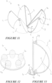
- Figure 12 shows the projections 16 which the connection may comprise, the projections 16 each to be associated with a corresponding hole 17 of the first end 8 of a body 2.
- the projections 17 may be mated with the body 2 by an interference fit of the head of the projection once passed through the hole 17.
- either or both of the body of the connection 6 or projections 17 may be formed from a resilient or flexible material such that it may accommodate the pivoting or other movement of the bodies 2 away from or towards the assembled state.
- a view of such a projection 16 mated with a hole 17 of a body 2 is shown in Figure 13 .
- the apparatus 1 may further comprise a retainer or latch 10 (in the exemplary embodiment a circular cap) which engages with each of the multiple bodies 2, preferably at or near the second end 9, in order to prevent their relative movement and thus retain the bodies 2 in their assembled state.
- a retainer or latch 10 in the exemplary embodiment a circular cap
- FIG. 8 One exemplary association of the retainer 10 with the second ends 9 of the bodies 2 is shown in Figure 8 .
- the retainer 10 is a circular cap, it preferably comprises a plurality of projections 13 which correspond with a hole 14 in the second end 9 of each body to be retained.
- the connection between the projections 13 and their respective holes 14 is preferably such as to retain the second ends 9 of the multiple bodies 2 in place, yet such that it is able to be released when it is desired to allow or cause at least one second end 9 of a body 2 to move away from the assembled state.
- a tab 15 may be provided to enable a user to grasp the retainer 10.
- each of the multiple bodies 2 is identical. Even the retainer latch 10 and hinging connection 6 can be implemented while employing multiple bodies 2 of identical form. Although not all embodiments require that the multiple bodies 2 are identical, it is a significant feature of the present design because it greatly simplifies the process and cost for manufacture of the apparatus.
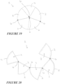
- segment shaped multiple bodies 2 may not be connected via a hinged or pivoting connection 6 at the first end, but instead the connection is along a side edge (between the first and second ends 8, 9) such the bodies 2 move relative one another in a concertina fashion.
- Such a configuration is shown in Figures 18 and 19-20 .
- the "concertina" is expanded the cavity 3 openings 5 are revealed.
- the previously described circular cap could be similarly employed to latch the bodies together in the assembled state, however a person skilled in the art would appreciate that other types of retainers 10 could be used to retain the multiple bodies 2 in the assembled state.
- the same purpose could be served by an elastic band encircling the circumference of the three dimensional sphere formed by the multiple bodies in their assembled state as seen in Figure 1 or 19 .
- one or more of the multiple bodies may not be permanently connected to the others, and in some examples all of the bodies 2 may be free of permanent connection with each other.
- the multiple bodies could be of substantially cuboid shape, and may instead assume the assembled state by stacking on top of each other or releasably interlocking.
- each cavity 3 can be revealed and/or accessed in sequence, i.e. one at a time. This is to increase the length of the process for revealing toys 4 housed inside the apparatus 1, and thus extending the period of interest and entertainment for the child.
- this could be achieved by applying a selector mechanism to the hinges/pivots 6 so that only one of the segmented multiple bodies 2 can be moved away from the assembled state at a time to reveal its associated cavity 3.
- a further convenient way to achieve this is to apply a (preferably opaque) cover or seal 12 over the opening of the cavity 3which must be removed before any items/toy(s) housed within the cavity can be viewed, accessed and/or withdrawn from the cavity 3.
- the cover or seal 12 may be a foil seal, adhesive or heat sealed about the edges of the cavity opening, or may be frangible, edible, deformable or otherwise removable to permit access to the interior of the cavity.
- the cover or seal 12 may be a foil seal, adhesive or heat sealed about the edges of the cavity opening, or may be frangible, edible, deformable or otherwise removable to permit access to the interior of the cavity.
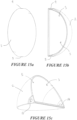
- the bodies 2 are in capsule form with a peel-off seal 12 covering the entirety of each cavity 3 opening 5.
- the cavity opening defines one whole face of the body segment.
- Figure 14b Shown in Figure 14b is the apparatus 1 of Figure 14a , where a seal 12 has been partially peeled away from the opening 5 of the body 2 to reveal a toy 4 held within the cavity 3.
- each segment may be a toy like a figurine, eraser, hairclip, model of the Eiffel Tower.
- Each segment may have a different item. Whilst each segment may be identical in shape, some or all segments of the assembly may be different in shape.
- the plurality of bodies may be frangibly connected to the apparatus, or otherwise able to be independently detached. This feature may especially be present in embodiments where the cavity opening is sealed or covered, in which case the individual bodies can be broken off and distributed.
- the frangible connection may be provided by a hinged or pivoting connection 6 as previously described which is weakened or provided of a material able to be torn by a user. Such a user could be someone of adult strength or more likely could be a child.
- One such method of frangible or tearable connection 6 may be provided using the connection 6 shown in Figures 11-13 wherein the projections 16 are able to be torn away from the body of the connection 6.
Landscapes
- Engineering & Computer Science (AREA)
- Mechanical Engineering (AREA)
- Toys (AREA)
Applications Claiming Priority (3)
| Application Number | Priority Date | Filing Date | Title |
|---|---|---|---|
| US201762459471P | 2017-02-15 | 2017-02-15 | |
| EP18754756.7A EP3582864B1 (de) | 2017-02-15 | 2018-02-14 | Vorrichtung zur aufnahme und freilegung von mehreren kinderspielzeugen |
| PCT/IB2018/050887 WO2018150328A1 (en) | 2017-02-15 | 2018-02-14 | Apparatus for housing and revealing a plurality of children's toys |
Related Parent Applications (1)
| Application Number | Title | Priority Date | Filing Date |
|---|---|---|---|
| EP18754756.7A Division EP3582864B1 (de) | 2017-02-15 | 2018-02-14 | Vorrichtung zur aufnahme und freilegung von mehreren kinderspielzeugen |
Publications (2)
| Publication Number | Publication Date |
|---|---|
| EP4241861A2 true EP4241861A2 (de) | 2023-09-13 |
| EP4241861A3 EP4241861A3 (de) | 2024-01-03 |
Family
ID=63106130
Family Applications (2)
| Application Number | Title | Priority Date | Filing Date |
|---|---|---|---|
| EP18754756.7A Active EP3582864B1 (de) | 2017-02-15 | 2018-02-14 | Vorrichtung zur aufnahme und freilegung von mehreren kinderspielzeugen |
| EP23187924.8A Pending EP4241861A3 (de) | 2017-02-15 | 2018-02-14 | Vorrichtung zur aufnahme und freilegung von mehreren kinderspielzeugen |
Family Applications Before (1)
| Application Number | Title | Priority Date | Filing Date |
|---|---|---|---|
| EP18754756.7A Active EP3582864B1 (de) | 2017-02-15 | 2018-02-14 | Vorrichtung zur aufnahme und freilegung von mehreren kinderspielzeugen |
Country Status (10)
| Country | Link |
|---|---|
| US (2) | US10562663B2 (de) |
| EP (2) | EP3582864B1 (de) |
| CN (1) | CN110446536A (de) |
| AU (2) | AU2018220892B2 (de) |
| CA (1) | CA3052921C (de) |
| DK (1) | DK3582864T3 (de) |
| ES (1) | ES2960454T3 (de) |
| FI (1) | FI3582864T3 (de) |
| PL (1) | PL3582864T3 (de) |
| WO (1) | WO2018150328A1 (de) |
Families Citing this family (12)
| Publication number | Priority date | Publication date | Assignee | Title |
|---|---|---|---|---|
| USD839368S1 (en) * | 2017-11-20 | 2019-01-29 | Mathew Peter Mowbray | Ball |
| KR102129175B1 (ko) * | 2018-09-10 | 2020-07-01 | 안수연 | 세탁볼 |
| JP7196501B2 (ja) * | 2018-09-26 | 2022-12-27 | 大日本印刷株式会社 | 包装体 |
| JP7196499B2 (ja) * | 2018-09-26 | 2022-12-27 | 大日本印刷株式会社 | 包装体 |
| JP7196500B2 (ja) * | 2018-09-26 | 2022-12-27 | 大日本印刷株式会社 | 包装体 |
| EP4079651B1 (de) * | 2019-12-19 | 2026-04-22 | T-Arts Company, Ltd. | Spielzeugbehälter |
| USD944000S1 (en) * | 2020-01-16 | 2022-02-22 | Prym Consumer Usa Inc. | Yarn holder apparatus |
| USD1026139S1 (en) * | 2020-12-25 | 2024-05-07 | Dongguan Saienchuangke Technology Co., Ltd | Water ball |
| CN118615720A (zh) * | 2020-12-25 | 2024-09-10 | 东莞市赛恩创客科技有限公司 | 玩具水球 |
| USD1030929S1 (en) | 2020-12-25 | 2024-06-11 | Dongguan Saienchuangke Technology Co., Ltd | Spherical toy water ball |
| US12544682B2 (en) * | 2021-06-01 | 2026-02-10 | Lightuptoys.Com Llc | Illuminating inflatable balloon toy |
| USD1034861S1 (en) | 2021-12-14 | 2024-07-09 | Dongguan Saienchuangke Technology Co., Ltd | Toy water ball |
Citations (1)
| Publication number | Priority date | Publication date | Assignee | Title |
|---|---|---|---|---|
| US20110123687A1 (en) | 2009-11-21 | 2011-05-26 | Candy Treasure, LLC | Separatable Shell for Receiving Candy Coating and Storing Toy |
Family Cites Families (28)
| Publication number | Priority date | Publication date | Assignee | Title |
|---|---|---|---|---|
| FR1193845A (de) * | 1959-11-05 | |||
| US1409082A (en) * | 1921-07-13 | 1922-03-07 | Corbett William John | Spherical globe |
| US1524367A (en) * | 1922-09-22 | 1925-01-27 | John G Papageorge | Confection |
| GB406680A (en) * | 1931-12-10 | 1934-02-19 | Schatz Paul | Improvements in or relating to boxes or containers |
| BE788828A (fr) * | 1971-09-16 | 1973-03-14 | Roussel Uclaf | Nouveaux derives organophosphores heterocycliques et procede depreparation |
| US4765501A (en) * | 1987-09-02 | 1988-08-23 | Joe Kao | Toy container |
| US5676253A (en) * | 1996-07-11 | 1997-10-14 | Hsu; Yi-Kung | Combination-type tool box |
| US5792496A (en) * | 1997-01-10 | 1998-08-11 | Fekete; Ferenc | Edible shell/thermoplastic container system |
| US6244501B1 (en) * | 1999-04-29 | 2001-06-12 | Deokwhan Choi | Multi-purpose package assembly |
| USD463120S1 (en) * | 2000-11-01 | 2002-09-24 | Hiromori Inc. | Tool box |
| USD468535S1 (en) * | 2002-02-12 | 2003-01-14 | Mccormack Corinne | Multiple compartment carrying case |
| US20030234195A1 (en) * | 2002-06-24 | 2003-12-25 | Earl Milan Dennis | Container having adjusting compartments |
| US20050029735A1 (en) * | 2003-08-07 | 2005-02-10 | Fang Liu | Element of globe block game, and methods of making and use the same |
| ITTO20040363A1 (it) * | 2004-05-28 | 2004-08-28 | Produzioni Editoriali Aprile Spa | Contenitore multiplo. |
| US20090272659A1 (en) * | 2005-04-19 | 2009-11-05 | Stephanie A Kaiser | Cosmetic case |
| US20070102308A1 (en) * | 2005-11-09 | 2007-05-10 | Christian Tremblay | Snack container |
| JP4859206B2 (ja) * | 2006-02-20 | 2012-01-25 | 株式会社セガ トイズ | 玩具 |
| FR2911852B1 (fr) * | 2007-01-30 | 2011-04-01 | Chinguetti Associes | Conteneur deployable de bouteilles ou similaires |
| DE202007002562U1 (de) * | 2007-02-21 | 2008-07-03 | Kösters, Bärbel | Ball Puzzle |
| US7547019B2 (en) * | 2007-03-19 | 2009-06-16 | Ying-Jen Chen | Three-dimensional DIY assembly intelligence structure |
| EP2017180A1 (de) * | 2007-07-20 | 2009-01-21 | Philip Morris Products S.A. | Doppelpackung mit integriertem Verbindungsstück |
| CA2721804C (en) * | 2008-04-21 | 2013-11-12 | Mattel, Inc. | Dolls and doll stands |
| US20100301558A1 (en) * | 2009-05-29 | 2010-12-02 | Speegle John M | Spherical puzzle |
| DE102013000483A1 (de) * | 2013-01-15 | 2014-07-17 | Sanner Gmbh | Kindergesicherter Behälterverschluss |
| US20150210432A1 (en) * | 2014-01-29 | 2015-07-30 | The Plasticsam Limited | Object and food item storage device |
| US20160021915A1 (en) * | 2014-07-24 | 2016-01-28 | Michael Wayne Baxter | Food storage container and methods of use |
| DE102015101080A1 (de) * | 2015-01-26 | 2016-07-28 | Stephan Bohn | Verkaufsverpackung |
| US9931579B1 (en) * | 2017-01-17 | 2018-04-03 | Mga Entertainment, Inc. | Toy having multiple serial surprise reveals |
-
2018
- 2018-02-14 DK DK18754756.7T patent/DK3582864T3/da active
- 2018-02-14 CN CN201880012268.3A patent/CN110446536A/zh active Pending
- 2018-02-14 ES ES18754756T patent/ES2960454T3/es active Active
- 2018-02-14 EP EP18754756.7A patent/EP3582864B1/de active Active
- 2018-02-14 CA CA3052921A patent/CA3052921C/en active Active
- 2018-02-14 WO PCT/IB2018/050887 patent/WO2018150328A1/en not_active Ceased
- 2018-02-14 FI FIEP18754756.7T patent/FI3582864T3/fi active
- 2018-02-14 PL PL18754756.7T patent/PL3582864T3/pl unknown
- 2018-02-14 AU AU2018220892A patent/AU2018220892B2/en active Active
- 2018-02-14 EP EP23187924.8A patent/EP4241861A3/de active Pending
- 2018-02-15 US US15/897,569 patent/US10562663B2/en active Active
-
2020
- 2020-01-10 US US16/739,792 patent/US11192682B2/en active Active
-
2023
- 2023-06-30 AU AU2023204207A patent/AU2023204207A1/en not_active Abandoned
Patent Citations (1)
| Publication number | Priority date | Publication date | Assignee | Title |
|---|---|---|---|---|
| US20110123687A1 (en) | 2009-11-21 | 2011-05-26 | Candy Treasure, LLC | Separatable Shell for Receiving Candy Coating and Storing Toy |
Also Published As
| Publication number | Publication date |
|---|---|
| US11192682B2 (en) | 2021-12-07 |
| US20180229885A1 (en) | 2018-08-16 |
| EP3582864A1 (de) | 2019-12-25 |
| EP4241861A3 (de) | 2024-01-03 |
| AU2023204207A1 (en) | 2023-07-27 |
| CN110446536A (zh) | 2019-11-12 |
| WO2018150328A1 (en) | 2018-08-23 |
| EP3582864A4 (de) | 2020-12-23 |
| DK3582864T3 (da) | 2023-10-30 |
| AU2018220892B2 (en) | 2023-04-13 |
| US10562663B2 (en) | 2020-02-18 |
| CA3052921A1 (en) | 2018-08-23 |
| AU2018220892A1 (en) | 2019-10-03 |
| PL3582864T3 (pl) | 2024-01-22 |
| FI3582864T3 (fi) | 2023-10-30 |
| EP3582864B1 (de) | 2023-08-02 |
| US20200148411A1 (en) | 2020-05-14 |
| CA3052921C (en) | 2022-07-12 |
| ES2960454T3 (es) | 2024-03-04 |
Similar Documents
| Publication | Publication Date | Title |
|---|---|---|
| US11192682B2 (en) | Apparatus for housing and revealing a plurality of children's toys | |
| US5792496A (en) | Edible shell/thermoplastic container system | |
| ES2266637T3 (es) | Embalaje para multiples discos y procedimientos de fabricacion asociados. | |
| EP0951835B1 (de) | Essbare Artikel mit nicht-essbaren Behältern | |
| BG62358B1 (bg) | Опаковка за хранителни продукти | |
| ES2476797T3 (es) | Unidad de envase de bl�ster para productos de confitería | |
| US4988110A (en) | Combination board game and wrapper for edible play pieces | |
| EP3348317B1 (de) | Spielzeug mit mehreren seriellen überraschungsoffenbarungen | |
| JP2010000152A (ja) | 装飾体玩具成形セット | |
| US8859024B2 (en) | Separatable shell for receiving candy coating and storing toy | |
| HK40102320A (en) | Apparatus for housing and revealing a plurality of children's toys | |
| HK40023293A (en) | Apparatus for housing and revealing a plurality of children's toys | |
| HK40023293B (en) | Apparatus for housing and revealing a plurality of children's toys | |
| US20040226846A1 (en) | Decorative gift article | |
| KR100459773B1 (ko) | 식품포장용기 | |
| KR102517194B1 (ko) | 바람개비 또는 지우개가 탈착되게 구비되는 캔디 피리스틱 | |
| JP3128179U (ja) | 菓子類用容器 | |
| JP6926478B2 (ja) | 鏡餅セット容器および鏡餅セット | |
| JP2587592Y2 (ja) | 卵の玩具 | |
| WO2015185970A1 (en) | Packaging and display | |
| JP2018108855A (ja) | 鏡餅用容器および鏡餅形パック | |
| KR200406241Y1 (ko) | 다기능 완구 | |
| CN120020061A (zh) | 构造成用于新奇冷冻甜食的非食用胶囊 | |
| KR200296165Y1 (ko) | 저금통 겸용 캔디 포장용 용기 | |
| JP3080401U (ja) | 菓 子 |
Legal Events
| Date | Code | Title | Description |
|---|---|---|---|
| PUAI | Public reference made under article 153(3) epc to a published international application that has entered the european phase |
Free format text: ORIGINAL CODE: 0009012 |
|
| STAA | Information on the status of an ep patent application or granted ep patent |
Free format text: STATUS: THE APPLICATION HAS BEEN PUBLISHED |
|
| AC | Divisional application: reference to earlier application |
Ref document number: 3582864 Country of ref document: EP Kind code of ref document: P |
|
| AK | Designated contracting states |
Kind code of ref document: A2 Designated state(s): AL AT BE BG CH CY CZ DE DK EE ES FI FR GB GR HR HU IE IS IT LI LT LU LV MC MK MT NL NO PL PT RO RS SE SI SK SM TR |
|
| REG | Reference to a national code |
Ref country code: DE Ref legal event code: R079 Free format text: PREVIOUS MAIN CLASS: A63H0033000000 Ipc: A63F0009120000 |
|
| PUAL | Search report despatched |
Free format text: ORIGINAL CODE: 0009013 |
|
| AK | Designated contracting states |
Kind code of ref document: A3 Designated state(s): AL AT BE BG CH CY CZ DE DK EE ES FI FR GB GR HR HU IE IS IT LI LT LU LV MC MK MT NL NO PL PT RO RS SE SI SK SM TR |
|
| RIC1 | Information provided on ipc code assigned before grant |
Ipc: A63H 33/00 20060101ALI20231127BHEP Ipc: B65D 21/02 20060101ALI20231127BHEP Ipc: A63F 9/12 20060101AFI20231127BHEP |
|
| REG | Reference to a national code |
Ref country code: HK Ref legal event code: DE Ref document number: 40102320 Country of ref document: HK |
|
| STAA | Information on the status of an ep patent application or granted ep patent |
Free format text: STATUS: REQUEST FOR EXAMINATION WAS MADE |
|
| 17P | Request for examination filed |
Effective date: 20240702 |
|
| RBV | Designated contracting states (corrected) |
Designated state(s): AL AT BE BG CH CY CZ DE DK EE ES FI FR GB GR HR HU IE IS IT LI LT LU LV MC MK MT NL NO PL PT RO RS SE SI SK SM TR |
|
| RAP1 | Party data changed (applicant data changed or rights of an application transferred) |
Owner name: ZURU IP LIMITED |