EP4241890A1 - Procédé de commande et/ou de régulation de l'alimentation en matériau à traiter vers une installation de broyage et/ou de tamisage d'un dispositif de traitement de matériau - Google Patents
Procédé de commande et/ou de régulation de l'alimentation en matériau à traiter vers une installation de broyage et/ou de tamisage d'un dispositif de traitement de matériau Download PDFInfo
- Publication number
- EP4241890A1 EP4241890A1 EP23155167.2A EP23155167A EP4241890A1 EP 4241890 A1 EP4241890 A1 EP 4241890A1 EP 23155167 A EP23155167 A EP 23155167A EP 4241890 A1 EP4241890 A1 EP 4241890A1
- Authority
- EP
- European Patent Office
- Prior art keywords
- processed
- crushing
- determined
- processing device
- speed
- Prior art date
- Legal status (The legal status is an assumption and is not a legal conclusion. Google has not performed a legal analysis and makes no representation as to the accuracy of the status listed.)
- Granted
Links
Images

Classifications
-
- B—PERFORMING OPERATIONS; TRANSPORTING
- B02—CRUSHING, PULVERISING, OR DISINTEGRATING; PREPARATORY TREATMENT OF GRAIN FOR MILLING
- B02C—CRUSHING, PULVERISING, OR DISINTEGRATING IN GENERAL; MILLING GRAIN
- B02C25/00—Control arrangements specially adapted for crushing or disintegrating
-
- B—PERFORMING OPERATIONS; TRANSPORTING
- B02—CRUSHING, PULVERISING, OR DISINTEGRATING; PREPARATORY TREATMENT OF GRAIN FOR MILLING
- B02C—CRUSHING, PULVERISING, OR DISINTEGRATING IN GENERAL; MILLING GRAIN
- B02C23/00—Auxiliary methods or auxiliary devices or accessories specially adapted for crushing or disintegrating not provided for in preceding groups or not specially adapted to apparatus covered by a single preceding group
- B02C23/02—Feeding devices
-
- B—PERFORMING OPERATIONS; TRANSPORTING
- B02—CRUSHING, PULVERISING, OR DISINTEGRATING; PREPARATORY TREATMENT OF GRAIN FOR MILLING
- B02C—CRUSHING, PULVERISING, OR DISINTEGRATING IN GENERAL; MILLING GRAIN
- B02C23/00—Auxiliary methods or auxiliary devices or accessories specially adapted for crushing or disintegrating not provided for in preceding groups or not specially adapted to apparatus covered by a single preceding group
- B02C23/08—Separating or sorting of material, associated with crushing or disintegrating
-
- B—PERFORMING OPERATIONS; TRANSPORTING
- B07—SEPARATING SOLIDS FROM SOLIDS; SORTING
- B07B—SEPARATING SOLIDS FROM SOLIDS BY SIEVING, SCREENING, SIFTING OR BY USING GAS CURRENTS; SEPARATING BY OTHER DRY METHODS APPLICABLE TO BULK MATERIAL, e.g. LOOSE ARTICLES FIT TO BE HANDLED LIKE BULK MATERIAL
- B07B1/00—Sieving, screening, sifting, or sorting solid materials using networks, gratings, grids, or the like
- B07B1/42—Drive mechanisms, regulating or controlling devices, or balancing devices, specially adapted for screens
-
- B—PERFORMING OPERATIONS; TRANSPORTING
- B07—SEPARATING SOLIDS FROM SOLIDS; SORTING
- B07B—SEPARATING SOLIDS FROM SOLIDS BY SIEVING, SCREENING, SIFTING OR BY USING GAS CURRENTS; SEPARATING BY OTHER DRY METHODS APPLICABLE TO BULK MATERIAL, e.g. LOOSE ARTICLES FIT TO BE HANDLED LIKE BULK MATERIAL
- B07B1/00—Sieving, screening, sifting, or sorting solid materials using networks, gratings, grids, or the like
- B07B1/46—Constructional details of screens in general; Cleaning or heating of screens
Definitions
- the invention relates to a method for controlling and/or regulating the supply of material to be processed, in particular rock material, to a crushing and/or screening system of a material processing device, the material to be processed being guided to the crushing and/or screening system by means of a conveyor device .
- the invention also relates to a material processing device with a crushing and/or screening system for processing a material, in particular rock material, the material to be processed being guided to the crushing and/or screening system by means of a conveyor device.
- Such material processing devices can be used, for example, for shredding and/or sorting feed material, in particular rock material such as natural stone, concrete, bricks, or recycling material.
- the material to be processed is fed to a feed unit of the material processing device, for example in the form of a funnel, and fed to a crusher and/or a sieve via a conveyor device, for example a vibration feeder or a belt conveyor.
- the crusher can also be preceded by a pre-screening, for example in order to direct a fine fraction or a medium grain that already has a suitable grain size past the crusher.
- the pre-screening can be part of the conveying device.
- operating parameters such as the crusher filling level, utilization of the drive system or operating loads occurring on the crusher or sieve can be determined and used to regulate the feed. This means you can react to overload or underload.
- Such a procedure is from the DE 10 2017 124 958 A1 known.
- the object of the invention is to provide an improved method for controlling and/or regulating the supply of material to be processed to a crushing and/or screening system of a material processing device. It is a further object of the invention to provide a material processing device which is designed to carry out such a method.
- the task relating to the method is solved in that a condition of the material to be processed is determined, and/or that a volume flow of the material to be processed is determined, and that, taking into account the condition and/or the volume flow of the material to be processed, a conveying speed of Conveyor device is controlled and / or regulated.
- predictive process parameters namely the volume flow of the supplied material to be processed and/or a condition of the material to be processed, are used for the control. This can prevent or prevent the risk of overload and/or underload situations at least largely prevented. In this way, the production process and thus machine utilization, fuel efficiency and the quality of intermediate and final products can be improved.
- volume flow and/or quality can be determined before the material to be processed reaches the crushing and/or screening device. It can thus be determined how much material and/or material of what nature will reach the crushing and/or screening device. Taking these predictive parameters into account, the control of the conveying speed of the conveying device can be carried out in an improved manner.
- the determined volume flow and/or the determined condition are transferred to a data processing device, for example a computing and/or storage unit of the material processing device.
- a target conveying speed can be determined taking into account the transferred parameters.
- one or more tables, maps and/or functional relationships can be stored in the data processing device, which enable the determination of a target conveying speed based on the entered predictive parameters.
- the conveyor device can be controlled or regulated to this target conveying speed.
- the supply of material to be processed to the crushing and/or screening device can be regulated in advance so that no overload or underload occurs, or that the frequency of overload or underload situations can at least be reduced.
- the predictive parameter or parameters is/are used to set other and/or further machine parameters, such as, for example, to set a crushing gap, a rotor speed of an impact crusher, an excitation frequency and/or amplitude of a screening system and /or a pre-screen.
- a speed of the material to be processed is determined, that a layer height of the material to be processed on the conveyor device is determined, and that the volume flow of the material to be processed is determined from the determined layer height, the determined speed and a geometry of the conveyor device becomes.
- the condition can advantageously include a task size and/or a type of material to be processed, in particular a type of rock.
- a task size can, for example, be understood as an average grain size of the material to be processed.
- the feed size is a suitable parameter for drawing conclusions about the load acting on the crushing and/or screening device due to the processing of the material. It is therefore a suitable parameter to be taken into account when regulating and/or controlling the feed. For example, larger feed sizes, particularly larger rock fragments, may be more difficult to break, so it may be necessary to reduce conveying speed, particularly despite potentially low volume flow.
- the type of rock also influences the crushing and/or screening processes.
- the type of rock can in particular determine the hardness of the material to be processed, which can also have an influence on a suitable conveying speed, for example.
- condition and/or the layer height is determined using at least one sensor, and/or that the speed is determined using a speed measuring device.
- the at least one sensor is an imaging sensor, in particular a camera, stereo camera, time-of-flight camera or a laser scanner.
- a camera can be able to produce two-dimensional color images or black and white images.
- Means Stereo cameras, time-of-flight cameras or laser scanners can alternatively or additionally record three-dimensional images.
- images recorded by means of the at least one sensor are evaluated using at least one image recognition algorithm and/or object recognition algorithm, the evaluation being aimed at determining at least one target variable, preferably a quality and/or layer height of the material to be processed .
- the at least one target variable is divided into classes and that an image is assigned to one of the classes of the target variable by evaluating the images.
- the layer height can be divided into two to six classes. It is also conceivable that the task size of the material to be processed is divided into two or more classes.
- the at least one image recognition algorithm and/or object recognition algorithm is at least partially carried out by at least one artificial neural network (ANN), in particular by at least one ANN with several layers, preferably by at least one convolutional ANN.
- ANN artificial neural network
- the at least one ANN carries out at least parts of the image recognition algorithm and/or object recognition algorithm.
- ANNs are particularly suitable for determining the desired variables such as the layer height and/or a condition such as the type of rock and/or a task size based on the images recorded by the at least one sensor.
- ANNs are particularly suitable for assigning images to classes of a target size.
- the complexity of the ANN can be reduced if it is provided that several ANNs are used to evaluate the recorded images, in particular that an ANN is used to evaluate the layer height, another ANN is used to evaluate the type of material to be processed, and/or another KNN to Evaluation of the task size is used.
- the algorithms also have a modular structure, as the specialization means that the ANN modules can be expanded as desired without existing modules having to be retrained. For example, it is conceivable that initially only one ANN is used to determine the layer height. In this case, another module can simply be added later, for example to determine the type of rock, without the existing ANN for determining layer height having to be changed and/or retrained.
- the processing time for evaluating the recorded images can be reduced if it is provided that the several ANNs are operated in parallel in an operating mode, in particular that the ANNs are distributed over several computing units and / or CPUs, particularly preferably that each ANN has its own computing unit and/or CPU is assigned.
- the computing units and/or CPUs can be part of the data processing device of the material processing device.
- the speed measuring device is a mechanical speed measuring device. Measuring wheels with incremental measuring sensors, for example, come into consideration here. However, it is preferably provided that the speed measuring device is a non-contact speed measuring device, in particular a radar, ultrasound or laser-based speed measuring device.
- a residence time of the material to be processed is predicted based on the nature and the volume flow of the material to be processed, and that the predicted residence time of the material to be processed is used to control and / or regulate the conveying speed of the conveyor device .
- the residence time can be the length of time that a volume or mass element of material to be processed requires in order to be processed in the crushing and/or screening plant or in an area of the crushing and/or screening plant.
- the residence time can be the length of time that a volume or mass element of material to be processed remains in a crushing unit that causes comminution.
- an inverse throughput of the crushing and/or screening system can also correspond to a residence time. If the dwell time is now predicted and taken into account when regulating and/or controlling the conveying speed, the conveying speed can be regulated and/or controlled in such a way that there is enough time available for the material to be processed in accordance with the dwell time in which the crushing and/or screening system to be processed properly.
- a material supply can be achieved in terms of volume flow and/or conveying speed, which does not result in underfilling or overfilling and/or underloading or overloading, given a residence time of the material to be processed in the crushing and/or screening plant that corresponds to the predicted residence time the crushing and/or screening plant.
- An improved prediction of the residence time can be achieved if a system type and/or a system configuration, in particular a tool configuration, and/or a drive speed of the material processing device and/or the crushing and/or screening system are taken into account.
- the control and/or regulation of the conveying speed of the conveying device is continuously adjusted becomes.
- These parameters allow conclusions to be drawn as to whether the control and/or regulation of the conveyor speed is suitable in order to avoid overload and/or underload situations.
- the monitoring of one or more of the parameters mentioned is carried out, for example, by sensors.
- the sensors can then transfer the parameters, for example, to the data processing device of the material processing device.
- the stored tables and/or maps and/or functional relationships can be automated and/or manually adjusted. For example, if an overload has been detected, a target delivery speed for the current determined volume flow and/or for the determined nature of the material to be processed can be corrected downwards for future operation.
- one or more ANNs are used to regulate the conveying speed of the conveying device. These can be implemented, for example, on the data processing device. Based on the parameters described above, such as the filling level of the crushing system, and/or utilization of the crushing system and/or utilization of a drive motor of the crushing and/or screening system, the ANN(s) can be continuously supplied with training data. This makes it possible to achieve continuous refinement of the control and/or regulation.
- further parameters are used to control and/or regulate the conveying speed of the conveying device, in particular a layer height on a pre-screen and/or on the screening system and/or a filling level of the crushing system and/or a mechanical load on the crushing plant and/or the pre-screen, and/or a drive power of a drive motor of the crushing and/or screening system and/or a pre-screen.
- the task relating to the material processing device is solved in that the material processing device is set up to enable the determination of a condition of the material to be processed, and / or that the material processing device is set up to enable the determination of a volume flow of the material to be processed, and that the material processing device is set up to enable control and/or regulation of a conveying speed of the conveying device, taking into account the nature and/or the volume flow of the material to be processed.
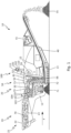
- Figure 1 shows a side, partially sectioned schematic representation of a material processing device 10.
- the material processing device 10 can be designed as a mobile system with a chassis 11 and, for example, a chain drive 13.
- the material processing device 10 can have a crushing system 50 and/or a screening system 30.
- the funnel 21 can serve to receive feed material 70 from an upstream conveyor system, for example an excavator, a wheel loader or a belt, and to direct it onto a conveyor device 23.
- the crushing plant 50 and/or the screening plant 30 can be fed feed material 70 in a conveying direction F for processing by means of the conveying device 23.
- the conveyor device 23 is designed as a vibration feeder.
- other configurations of a conveyor device 23, in particular as a conveyor belt, are also conceivable.
- the screening system 30 can, for example, be connected upstream of the crushing system 50 as a preliminary screening.
- the pre-screening can have a double-decker heavy-duty screen 31, which can have an upper deck 32 designed as a coarser sieve and a lower deck 34 designed as a finer sieve. It can be set in circular oscillation by a drive 33.
- the upper deck 32 can separate a fine fraction 71 and a medium grain 72 from the material 73 to be crushed.
- the lower deck 34 can separate the fine fraction 71 from the medium grain 72.
- the fine fraction 71 can either be passed out of the material shredding system 10 or, for example, fed to the medium grain 72 by appropriately positioning a bypass flap.
- the middle grain 72 can be guided past the crusher 50 via a bypass to a crusher discharge belt 40.
- the material 73 to be crushed is fed to the crusher 50 via a crusher inlet at the end of the preliminary screening.
- the pre-screening can be part of the conveyor 23.
- the material processing device 10 can have a crushing system 50 designed as a jaw crusher. However, it is also conceivable to provide other types of crushing plant 50, for example impact crushers, roller crushers or cone crushers.
- the crushing system 50 can have a fixed crushing jaw 51 and a moving crushing jaw 52, which can be aligned obliquely towards one another, so that a tapering shaft is formed between them.
- the shaft can open into a crushing gap 56.
- the crushing system 50 can, for example, be driven by a drive unit 12 via a drive shaft 55 connected to an eccentric 54.
- the eccentric 54 moves the moving crushing jaw 52 towards and away from the fixed crushing jaw 51 in an elliptical movement. During one Such a stroke also changes the distance between the crushing jaws 51, 52 in the area of the crushing gap 56.
- the moving crushing jaw 52 By moving the moving crushing jaw 52, the material 73 to be crushed is further and further crushed along the shaft until it has reached a grain size that allows it to leave the shaft through the crushing gap 56.
- the shredded material 74 falls onto the crusher discharge belt 40 and is further conveyed via this. For example, it can also be provided that it is guided past a magnetic separator 41, which separates ferromagnetic components from the shredded material 74 and ejects them laterally.
- the material processing device 10 can have a sensor 101. It is also conceivable that several sensors 101 are provided. As shown in the exemplary embodiment, the sensor 101 can be a camera. The camera may include a lens 102. The sensor 101 or the sensors 101 can be held on the material processing device 10 by means of a sensor holding device 110. The sensor holding device 110 can be a mast to which the sensor 101 or the sensors 101 is/are attached.
- the sensor 101 can be attached directly or indirectly to the material processing device 10 with a sensor adjustment device 111.
- the sensor 101 is indirectly attached to the material processing device 10 with a sensor adjustment device 111 via the sensor holding device 110.
- the sensor adjustment device 111 can, for example, enable an articulated connection to the sensor holding device 110, so that the sensor 101 or the sensors 101 can be pivoted, for example to enable different orientations of the sensor 101 or the sensors 101. It is also conceivable to attach the sensor 101 or the sensors 101 to the material processing device 10 and/or the sensor holding device 110 in a height-adjustable manner.
- the sensor 101 can have a detection volume 103. This can be given, for example, by an opening angle of a lens 102 used.
- the sensor 101 can be used alone and/or in combination with one Lens 102 may be designed to capture a measuring range 104.
- the measuring range 104 of the sensor 101 can be in the area of the conveyor 23.
- the detection area 104 is aligned so that parts of the material to be processed lie in it, which are located on the conveyor device 23 in the area of the pre-screening and in front of it in the conveying direction.
- the position of the measuring area 104 of the sensor 101 can also be chosen differently, although an area in the conveying direction in front of the screening (30) and/or crushing system (50) is preferably selected at least partially. It is also conceivable to provide several measuring areas 104 with different positions, especially when using several sensors 101.
- the crushing system 50 can be assigned a fill level sensor 61.
- This can be designed as an ultrasonic sensor.
- optical sensors for example a camera system
- radar sensors or mechanical sensors.
- the level sensor 61 can monitor the level of the crusher 50 with material 73 to be broken.
- material to be processed is conveyed on the conveyor device 23 in the direction of the crushing system 50 and/or the screening system 30.
- the material to be processed which is located in the measuring range 104 of one or more sensors 101, is monitored. For example, the condition of the material to be processed is continuously determined.
- the condition can be, for example, the size of the task and/or the type of material to be processed.
- the condition is determined, for example, with a sensor 101 designed as a camera.
- the condition is selected, for example using GPS data, from values typical for the respective location of use of the material processing device.
- At least one sensor 101 preferably records images 106 which are sent to a data processing device (not shown) of the material processing device 10 can be transmitted.
- the data processing device can be designed to execute image recognition algorithms to determine the nature of the material from the images 106.
- object recognition algorithms is also conceivable.
- an ANN 130, 131, 132, 133, 134 is used for image recognition.
- the ANN 130, 131, 132, 133, 134 can have been trained in advance with data sets of images 106 with a known characteristic of a condition such as the task size and/or the type of rock.
- the ANN 132 can recognize different classes 132.1, 132.2, 132.3, 132.4 of task sizes.
- the volume flow of the material to be processed is determined.
- a speed measuring device is preferably provided, which is not shown in the figures. From this, for example, a speed of the material to be processed located on the conveyor device 23 can be determined.
- the layer height of the material to be processed on the conveyor 23 can also be determined.
- the sensor 101 described above which is used to determine the condition, or alternatively another sensor 101 can be used.
- the layer height can also be divided into several classes 130.1, 130.2, 130.3, 130.4 etc. and evaluated using an ANN 130 as described above.
- the images 106 are preferably evaluated with regard to the various target variables using their own ANN 130, 131, 132, 133, 134, with several ANNs 130, 131, 132, 133, 134 preferably running in parallel on their own computing unit and/or CPU.
- Figure 2 shows an exemplary block representation of a parallel evaluation of images 106 by KNN 130.
- the recorded images 106 can be transferred to several KNN 130, 131, 132, 133, 134, for example one KNN 130 for evaluating the layer height and/or an ANN 131 for evaluating the type of rock and/or an ANN for evaluating the task variable 132 and/or further ANN 133 for evaluating further target variables can be provided.
- the target variables can each be divided into classes 130.1, 130.2, 130.3, 130.4, 131.1, 131.2, 131.3, 132.4 etc., with the same or different numbers of classes 130.1, 130.2 etc. for the different target variables to be determined in the ANN 130, 131 , 132, 133, 134 can be provided.
- the nature and/or the volume flow of the material to be processed can now be transferred to the data processing device, for example a computing and/or storage unit of the material processing device 10.
- the condition and/or the volume flow have already been determined previously using the data processing device, for example if the image and/or object recognition algorithms and/or the ANN 130, 131, 132, 133, 134 are implemented on it.
- a target conveying speed can now be determined taking into account the transferred parameters.
- one or more tables, maps and/or functional relationships can be stored in the data processing device, which enable the determination of a target conveying speed taking into account the entered predictive parameters.
- the conveyor device can be controlled or regulated to this target conveying speed.
- a residence time of the material to be processed in the crushing and/or screening plant 30 is predicted based on the determined condition and/or the volume flow.
- the length of stay can be a measure of how how long a volume or mass element of the material to be processed is expected to be required to be processed in the crushing 50 and/or screening plant 30 or in an area of the crushing 50 and/or screening plant 30, for example the residence time in the crushing chamber in front of the crushing gap 56
- the conveying speed can be controlled and/or regulated in a predictive manner so that there is no overload or underload situation, such as in the case of overfilling or underfilling of the crushing chamber.
- a target delivery speed can be determined which, in combination with the determined volume flow, allows a sufficient processing time, in particular in accordance with the predicted dwell time.
- the material is assigned to a hardness class 131.4, which corresponds to a high level of hardness.
- the material also has, for example, a high layer height and/or can be assigned to a high layer height class 130.4.
- a comparatively long residence time results.
- the length of stay can be determined from the parameters, for example by the data processing device.
- the data processing device can determine a dwell time taking into account the parameters from one or more tables, maps and/or functional relationships that are stored, for example, in the data processing device. It can also preferably be provided that the dwell time is determined from the determined parameters using an ANN.
- the target conveying speed of the conveying device 23 can be adjusted in such a way that the material being conveyed can be processed properly.
- the material then has sufficient processing time, which corresponds, for example, to the residence time.
- the fill level of the crushing plant 50 can be monitored using the fill level sensor 61.
- the monitored fill level can be transferred to the data processing device. If a level that is too high or too low is determined during operation despite the predictive control, the tables and/or maps and/or functional relationships can be adapted so that such situations can be better avoided in the future.
- a crusher fill level that is too high is determined.
- the dwell time to be predicted for the determined parameters such as the nature of the material to be processed can be corrected.
- the recordings 106 based on which the one or more ANNs 130, 131, 132, 133, 134 have determined a dwell time, can be provided (labeled) with the corrected dwell time and assigned to the one or more ANNs 130, 131, 132, 133, 134 are made available as training data.
Landscapes
- Engineering & Computer Science (AREA)
- Food Science & Technology (AREA)
- Disintegrating Or Milling (AREA)
Applications Claiming Priority (1)
| Application Number | Priority Date | Filing Date | Title |
|---|---|---|---|
| DE102022105343.1A DE102022105343A1 (de) | 2022-03-08 | 2022-03-08 | Verfahren zur Steuerung und/oder Regelung der Zuförderung zu bearbeitenden Materials zu einer Brech- und/oder Siebanlage einer Materialverarbeitungseinrichtung |
Publications (2)
| Publication Number | Publication Date |
|---|---|
| EP4241890A1 true EP4241890A1 (fr) | 2023-09-13 |
| EP4241890B1 EP4241890B1 (fr) | 2026-04-01 |
Family
ID=85175901
Family Applications (1)
| Application Number | Title | Priority Date | Filing Date |
|---|---|---|---|
| EP23155167.2A Active EP4241890B1 (fr) | 2022-03-08 | 2023-02-06 | Procédé de commande et/ou de régulation de l'alimentation en matériau à traiter vers une installation de broyage et/ou de tamisage d'un dispositif de traitement de matériau |
Country Status (4)
| Country | Link |
|---|---|
| US (1) | US12599912B2 (fr) |
| EP (1) | EP4241890B1 (fr) |
| CN (1) | CN116727091A (fr) |
| DE (1) | DE102022105343A1 (fr) |
Families Citing this family (1)
| Publication number | Priority date | Publication date | Assignee | Title |
|---|---|---|---|---|
| CN118594744B (zh) * | 2024-06-17 | 2025-04-08 | 河南福淮半导体材料有限公司 | 一种石英砂新材料生产自动化控制系统 |
Citations (5)
| Publication number | Priority date | Publication date | Assignee | Title |
|---|---|---|---|---|
| WO2009156585A1 (fr) * | 2008-06-27 | 2009-12-30 | Metso Minerals Inc. | Procédé et matériel de commande d'un processus de broyage |
| DE102012016332B4 (de) * | 2012-08-20 | 2016-11-03 | Steinert Elektromagnetbau Gmbh | Verfahren zur Steuerung und/oder Regelung eines Volumenstromes, eines Schüttgutes oder von Schüttgütern, insbesondere von mineralischen Schüttgütern, von Abfallstoffen, von Rohstoffen oder von Materialen bzw. Vorrichtung zur Durchführung des zuvor genannten Verfahrens |
| DE102017124958A1 (de) | 2017-10-25 | 2019-04-25 | Kleemann Gmbh | Verfahren zum lastabhängigen Betrieb einer Materialzerkleinerungsanlage |
| WO2020193137A1 (fr) * | 2019-03-26 | 2020-10-01 | Thyssenkrupp Industrial Solutions Ag | Procédé de classification approximative de la répartition de tailles de particules d'un produit en vrac |
| AT523812A1 (de) * | 2020-05-13 | 2021-11-15 | Rubble Master Hmh Gmbh | Verfahren zur Regelung eines Schwingförderers |
Family Cites Families (16)
| Publication number | Priority date | Publication date | Assignee | Title |
|---|---|---|---|---|
| DE3411540A1 (de) | 1984-03-29 | 1985-10-10 | Fried. Krupp Gmbh, 4300 Essen | Verfahren und vorrichtung zur ermittlung des foerdergutmengenstromes von bandfoerderern |
| AU2003212051B2 (en) | 2002-07-10 | 2004-09-23 | Opdetech Pty Ltd | Opal sorting multi-apparatus assembly |
| US9156192B2 (en) * | 2009-03-16 | 2015-10-13 | Blue Diamond Technologies, Ltd. | Micro-erosion process for controlling variable crumb rubber mesh size |
| RU2014116670A (ru) * | 2014-04-23 | 2015-10-27 | Петров Алексей Иванович | Способ комплексной переработки бурых углей и леонардита в гуминовые удобрения, препараты и в топливные брикеты и механохимический реактор переработки высоковязких сред |
| CN103990538A (zh) | 2014-06-03 | 2014-08-20 | 南京凯盛国际工程有限公司 | 一种辊压机用备料装置 |
| FI20155908A1 (fi) | 2015-12-01 | 2017-06-02 | Outotec Finland Oy | Menetelmä ja järjestely jauhinpiirillä varustetun hienonnusprosessin ohjaamiseksi |
| FI20155909A7 (fi) | 2015-12-01 | 2017-06-02 | Outotec Finland Oy | Menetelmä ja järjestely hienonnusprosessin ohjaamiseksi |
| CN107755063A (zh) | 2016-08-18 | 2018-03-06 | 中国铁建重工集团有限公司 | 一种移动破碎站及其给料控制方法和系统 |
| IT201700023354A1 (it) | 2017-03-02 | 2018-09-02 | Cams Srl | Un metodo di controllo di un impianto di trattamento di elementi da riciclare o smaltire e impianto di trattamento di elementi da riciclare o smaltire |
| US10589285B2 (en) * | 2017-07-10 | 2020-03-17 | Joy Global Underground Mining Llc | Feeder breaker with reduced fines generation |
| US10695800B2 (en) * | 2017-09-06 | 2020-06-30 | Aqseptence Group Pty Ltd. | Sieve bend |
| EP3883699B1 (fr) | 2018-11-22 | 2023-11-01 | J.M. Canty Inc. | Procédé et système de mesure de débit volumique |
| CN110064496A (zh) | 2019-04-24 | 2019-07-30 | 福建南方路面机械有限公司 | 一种防止颚式破碎机过载停机的自动控制系统及方法 |
| EP3959653A1 (fr) * | 2019-06-05 | 2022-03-02 | X Development LLC | Détermination de caractéristiques de minerai |
| US12187617B2 (en) * | 2019-10-22 | 2025-01-07 | Hemlock Semiconductor Operations Llc | Method and apparatus for removal of surface carbon from polysilicon |
| US11465155B1 (en) * | 2021-06-16 | 2022-10-11 | Propflow, Llc | Wellsite wet screening systems for proppants and methods of using same |
-
2022
- 2022-03-08 DE DE102022105343.1A patent/DE102022105343A1/de active Granted
-
2023
- 2023-02-06 EP EP23155167.2A patent/EP4241890B1/fr active Active
- 2023-02-20 US US18/171,442 patent/US12599912B2/en active Active
- 2023-03-08 CN CN202310213631.0A patent/CN116727091A/zh active Pending
Patent Citations (5)
| Publication number | Priority date | Publication date | Assignee | Title |
|---|---|---|---|---|
| WO2009156585A1 (fr) * | 2008-06-27 | 2009-12-30 | Metso Minerals Inc. | Procédé et matériel de commande d'un processus de broyage |
| DE102012016332B4 (de) * | 2012-08-20 | 2016-11-03 | Steinert Elektromagnetbau Gmbh | Verfahren zur Steuerung und/oder Regelung eines Volumenstromes, eines Schüttgutes oder von Schüttgütern, insbesondere von mineralischen Schüttgütern, von Abfallstoffen, von Rohstoffen oder von Materialen bzw. Vorrichtung zur Durchführung des zuvor genannten Verfahrens |
| DE102017124958A1 (de) | 2017-10-25 | 2019-04-25 | Kleemann Gmbh | Verfahren zum lastabhängigen Betrieb einer Materialzerkleinerungsanlage |
| WO2020193137A1 (fr) * | 2019-03-26 | 2020-10-01 | Thyssenkrupp Industrial Solutions Ag | Procédé de classification approximative de la répartition de tailles de particules d'un produit en vrac |
| AT523812A1 (de) * | 2020-05-13 | 2021-11-15 | Rubble Master Hmh Gmbh | Verfahren zur Regelung eines Schwingförderers |
Also Published As
| Publication number | Publication date |
|---|---|
| US12599912B2 (en) | 2026-04-14 |
| EP4241890B1 (fr) | 2026-04-01 |
| DE102022105343A1 (de) | 2023-09-14 |
| US20230285981A1 (en) | 2023-09-14 |
| CN116727091A (zh) | 2023-09-12 |
Similar Documents
| Publication | Publication Date | Title |
|---|---|---|
| DE102021117537B3 (de) | Gesteinsverarbeitungsmaschine mit Bilderfassung und mit Bildverarbeitung durch ein neuronales Netzwerk | |
| EP3700677A1 (fr) | Procédé permettant de faire fonctionner une installation de broyage de matériaux en fonction de la charge | |
| DE102022105345A1 (de) | Verfahren zur Steuerung und/oder Regelung der Zuförderung zu bearbeitenden Materials zu einer Brech- und/oder Siebanlage einer Materialverarbeitungseinrichtung | |
| EP2001607A2 (fr) | Procédé et dispositif de classification souple de fragments de silicium polycristallin | |
| DE102010012620A1 (de) | Verfahren zum Betrieb einer Mühle | |
| EP3714981B1 (fr) | Installation de traitement, en particulier installation de concassage, en particulier concasseur | |
| DE102022118042B3 (de) | Gesteinsverarbeitungsanlage mit wenigstens zwei Wertkorn-Sieblinien und von den Sieblinienausträgen abhängiger automatisierter Betriebsführung | |
| EP4241890B1 (fr) | Procédé de commande et/ou de régulation de l'alimentation en matériau à traiter vers une installation de broyage et/ou de tamisage d'un dispositif de traitement de matériau | |
| AT523806B1 (de) | Verfahren zur Klemmkornabreinigung bei Brechern | |
| EP4201528A1 (fr) | Procédé de réglage d'un état de fonctionnement d'au moins une installation mobile de traitement de minéraux | |
| EP4052559A1 (fr) | Procédé de détection des longueurs d'une particule | |
| EP3936234A1 (fr) | Installation de concassage mobile et procédé de fabrication d'un produit final minéral en grain concassé | |
| DE19708185C2 (de) | Verfahren und Einrichtung zum Beschicken und Betreiben einer Anlage zum Zerkleinern von recycelbaren Alt-Gütern | |
| EP3452225B1 (fr) | Installation de broyage et procédé de broyage pour le broyage de déchets d'aluminium | |
| EP0729822B1 (fr) | Méthode de contrÔle de machines à extruder | |
| EP3954462B1 (fr) | Dispositif de broyage pourvu de dispositif de refroidissement, ainsi que procédé de fonctionnement | |
| AT523812B1 (de) | Verfahren zur Regelung eines Schwingförderers | |
| DE102022118032B3 (de) | Mobile Gesteinsverarbeitungsvorrichtung mit verbesserter Planung einer diskontinuierlichen Materialaufgabe | |
| DE69810939T2 (de) | Verfahren und vorrichtung zur zerkleinerung von stückformigem rohmaterial in einem körnigen material mit definierter korngrössenverteilung | |
| DE102023101025B3 (de) | Gesteinsverarbeitungsmaschine mit Verschleißbeurteilung und qualitativer Bewertung der Verschleißbeurteilung | |
| EP0811427A2 (fr) | Procédé de réglage du débit de déchargement d'une installation de broyage | |
| EP2965819A1 (fr) | Dispositif de réglage et/ou commande d'un moteur à combustion interne | |
| EP4241891A1 (fr) | Procédé de détermination de la hauteur de couche d'un matériau de chargement alimentant une installation de concassage et/ou de tamisage d'un dispositif de traitement de matériau | |
| WO2026077734A1 (fr) | Procédé de régulation et/ou de commande d'installations de traitement d'emballages légers et/ou d'ordures ménagères | |
| DE102024130137A1 (de) | Vorbrecher für Brechanlage |
Legal Events
| Date | Code | Title | Description |
|---|---|---|---|
| PUAI | Public reference made under article 153(3) epc to a published international application that has entered the european phase |
Free format text: ORIGINAL CODE: 0009012 |
|
| STAA | Information on the status of an ep patent application or granted ep patent |
Free format text: STATUS: THE APPLICATION HAS BEEN PUBLISHED |
|
| AK | Designated contracting states |
Kind code of ref document: A1 Designated state(s): AL AT BE BG CH CY CZ DE DK EE ES FI FR GB GR HR HU IE IS IT LI LT LU LV MC ME MK MT NL NO PL PT RO RS SE SI SK SM TR |
|
| STAA | Information on the status of an ep patent application or granted ep patent |
Free format text: STATUS: REQUEST FOR EXAMINATION WAS MADE |
|
| 17P | Request for examination filed |
Effective date: 20240312 |
|
| RBV | Designated contracting states (corrected) |
Designated state(s): AL AT BE BG CH CY CZ DE DK EE ES FI FR GB GR HR HU IE IS IT LI LT LU LV MC ME MK MT NL NO PL PT RO RS SE SI SK SM TR |
|
| GRAP | Despatch of communication of intention to grant a patent |
Free format text: ORIGINAL CODE: EPIDOSNIGR1 |
|
| STAA | Information on the status of an ep patent application or granted ep patent |
Free format text: STATUS: GRANT OF PATENT IS INTENDED |
|
| RIC1 | Information provided on ipc code assigned before grant |
Ipc: B02C 23/00 20060101AFI20251216BHEP Ipc: B02C 23/02 20060101ALI20251216BHEP Ipc: B02C 25/00 20060101ALI20251216BHEP |
|
| INTG | Intention to grant announced |
Effective date: 20260102 |
|
| GRAS | Grant fee paid |
Free format text: ORIGINAL CODE: EPIDOSNIGR3 |
|
| GRAA | (expected) grant |
Free format text: ORIGINAL CODE: 0009210 |
|
| STAA | Information on the status of an ep patent application or granted ep patent |
Free format text: STATUS: THE PATENT HAS BEEN GRANTED |
|
| AK | Designated contracting states |
Kind code of ref document: B1 Designated state(s): AL AT BE BG CH CY CZ DE DK EE ES FI FR GB GR HR HU IE IS IT LI LT LU LV MC ME MK MT NL NO PL PT RO RS SE SI SK SM TR |
|
| REG | Reference to a national code |
Ref country code: CH Ref legal event code: F10 Free format text: ST27 STATUS EVENT CODE: U-0-0-F10-F00 (AS PROVIDED BY THE NATIONAL OFFICE) Effective date: 20260401 Ref country code: GB Ref legal event code: FG4D Free format text: NOT ENGLISH |
|
| REG | Reference to a national code |
Ref country code: DE Ref legal event code: R096 Ref document number: 502023003547 Country of ref document: DE |
|
| REG | Reference to a national code |
Ref country code: IE Ref legal event code: FG4D Free format text: LANGUAGE OF EP DOCUMENT: GERMAN |