EP4242007A1 - Système de traitement et unité de relais - Google Patents
Système de traitement et unité de relais Download PDFInfo
- Publication number
- EP4242007A1 EP4242007A1 EP23161280.5A EP23161280A EP4242007A1 EP 4242007 A1 EP4242007 A1 EP 4242007A1 EP 23161280 A EP23161280 A EP 23161280A EP 4242007 A1 EP4242007 A1 EP 4242007A1
- Authority
- EP
- European Patent Office
- Prior art keywords
- unit
- recording apparatus
- positioning guide
- processing system
- receiving portion
- Prior art date
- Legal status (The legal status is an assumption and is not a legal conclusion. Google has not performed a legal analysis and makes no representation as to the accuracy of the status listed.)
- Pending
Links
Images





Classifications
-
- B—PERFORMING OPERATIONS; TRANSPORTING
- B41—PRINTING; LINING MACHINES; TYPEWRITERS; STAMPS
- B41J—TYPEWRITERS; SELECTIVE PRINTING MECHANISMS, i.e. MECHANISMS PRINTING OTHERWISE THAN FROM A FORME; CORRECTION OF TYPOGRAPHICAL ERRORS
- B41J29/00—Details of, or accessories for, typewriters or selective printing mechanisms not otherwise provided for
- B41J29/12—Guards, shields or dust excluders
- B41J29/13—Cases or covers
-
- B—PERFORMING OPERATIONS; TRANSPORTING
- B41—PRINTING; LINING MACHINES; TYPEWRITERS; STAMPS
- B41J—TYPEWRITERS; SELECTIVE PRINTING MECHANISMS, i.e. MECHANISMS PRINTING OTHERWISE THAN FROM A FORME; CORRECTION OF TYPOGRAPHICAL ERRORS
- B41J3/00—Typewriters or selective printing or marking mechanisms characterised by the purpose for which they are constructed
- B41J3/44—Typewriters or selective printing mechanisms having dual functions or combined with, or coupled to, apparatus performing other functions
- B41J3/445—Printers integrated in other types of apparatus, e.g. printers integrated in cameras
-
- G—PHYSICS
- G03—PHOTOGRAPHY; CINEMATOGRAPHY; ANALOGOUS TECHNIQUES USING WAVES OTHER THAN OPTICAL WAVES; ELECTROGRAPHY; HOLOGRAPHY
- G03G—ELECTROGRAPHY; ELECTROPHOTOGRAPHY; MAGNETOGRAPHY
- G03G21/00—Arrangements not provided for by groups G03G13/00 - G03G19/00, e.g. cleaning, elimination of residual charge
- G03G21/16—Mechanical means for facilitating the maintenance of the apparatus, e.g. modular arrangements
- G03G21/1642—Mechanical means for facilitating the maintenance of the apparatus, e.g. modular arrangements for connecting the different parts of the apparatus
- G03G21/1647—Mechanical connection means
-
- B—PERFORMING OPERATIONS; TRANSPORTING
- B41—PRINTING; LINING MACHINES; TYPEWRITERS; STAMPS
- B41J—TYPEWRITERS; SELECTIVE PRINTING MECHANISMS, i.e. MECHANISMS PRINTING OTHERWISE THAN FROM A FORME; CORRECTION OF TYPOGRAPHICAL ERRORS
- B41J11/00—Devices or arrangements of selective printing mechanisms, e.g. ink-jet printers or thermal printers, for supporting or handling copy material in sheet or web form
- B41J11/0045—Guides for printing material
-
- B—PERFORMING OPERATIONS; TRANSPORTING
- B65—CONVEYING; PACKING; STORING; HANDLING THIN OR FILAMENTARY MATERIAL
- B65H—HANDLING THIN OR FILAMENTARY MATERIAL, e.g. SHEETS, WEBS, CABLES
- B65H33/00—Forming counted batches in delivery pile or stream of articles
-
- B—PERFORMING OPERATIONS; TRANSPORTING
- B65—CONVEYING; PACKING; STORING; HANDLING THIN OR FILAMENTARY MATERIAL
- B65H—HANDLING THIN OR FILAMENTARY MATERIAL, e.g. SHEETS, WEBS, CABLES
- B65H37/00—Article or web delivery apparatus incorporating devices for performing specified auxiliary operations
- B65H37/04—Article or web delivery apparatus incorporating devices for performing specified auxiliary operations for securing together articles or webs, e.g. by adhesive, stitching or stapling
-
- G—PHYSICS
- G03—PHOTOGRAPHY; CINEMATOGRAPHY; ANALOGOUS TECHNIQUES USING WAVES OTHER THAN OPTICAL WAVES; ELECTROGRAPHY; HOLOGRAPHY
- G03G—ELECTROGRAPHY; ELECTROPHOTOGRAPHY; MAGNETOGRAPHY
- G03G21/00—Arrangements not provided for by groups G03G13/00 - G03G19/00, e.g. cleaning, elimination of residual charge
- G03G21/16—Mechanical means for facilitating the maintenance of the apparatus, e.g. modular arrangements
- G03G21/1604—Arrangement or disposition of the entire apparatus
- G03G21/1619—Frame structures
-
- B—PERFORMING OPERATIONS; TRANSPORTING
- B65—CONVEYING; PACKING; STORING; HANDLING THIN OR FILAMENTARY MATERIAL
- B65H—HANDLING THIN OR FILAMENTARY MATERIAL, e.g. SHEETS, WEBS, CABLES
- B65H2601/00—Problem to be solved or advantage achieved
- B65H2601/60—Miscellaneous
-
- B—PERFORMING OPERATIONS; TRANSPORTING
- B65—CONVEYING; PACKING; STORING; HANDLING THIN OR FILAMENTARY MATERIAL
- B65H—HANDLING THIN OR FILAMENTARY MATERIAL, e.g. SHEETS, WEBS, CABLES
- B65H2801/00—Application field
- B65H2801/24—Post -processing devices
- B65H2801/31—Devices located downstream of industrial printers
Definitions
- the present disclosure relates to a processing system and a relay unit.
- JP-A-2016-133635 discloses a known technology relating to a recording system, which is an example of a processing system of this kind.
- JP-A-2016-133635 discloses an image forming system in which an image forming apparatus having an inner output portion is coupled to a post-processing device.
- the image forming system includes a relay device detachably attached to the inner output portion.
- the relay device of the above-described known technology which is detachably attached to the inner output portion, often requires alignment at a tucked-away position of the image forming apparatus.
- the alignment is difficult for a common positioning mechanism. Due to the difficult alignment, the relay device may collide with the image forming apparatus, resulting in damage.
- a processing system includes a first unit configured to perform a first process and a second unit configured to perform a second process and coupled to the first unit by a positioning mechanism.
- the positioning mechanism includes: a positioner including a first insertion portion that is included in one of the first unit and the second unit and a first receiving portion that is included in the other of the first unit and the second unit and to which the first insertion portion is inserted to position the first unit and the second unit; and a positioning guide including a second insertion portion that is included in one of the first unit and the second unit and a second receiving portion that is included in the other of the first unit and the second unit and to which the second insertion portion is inserted to guide the first insertion portion to an insertable position into the first receiving portion, and the insertion of the positioning guide precedes the insertion of the positioner.
- a relay unit is coupled to a recording apparatus by a positioning mechanism at an inner output portion of the recording apparatus and includes an inlet portion configured to receive a medium recorded by the recording apparatus.
- the relay unit is configured to transport the medium to a post-processing device that performs predetermined post-processing on the medium.
- the positioning mechanism includes: a positioner including a first insertion portion that is included in one of the recording apparatus and the relay unit and a first receiving portion that is included in the other of the recording apparatus and the relay unit and to which the first insertion portion is inserted to position the recording apparatus and the relay unit; and a positioning guide including a second insertion portion that is included in one of the recording apparatus and the relay unit and a second receiving portion that is included in the other of the recording apparatus and the relay unit and to which the second insertion portion is inserted to guide the first insertion portion to an insertable position into the first receiving portion, and the insertion of the positioning guide precedes the insertion of the positioner.
- a processing system includes a first unit configured to perform a first process and a second unit configured to perform a second process and coupled to the first unit by a positioning mechanism.
- the positioning mechanism includes: a positioner including a first insertion portion that is included in one of the first unit and the second unit and a first receiving portion that is included in the other of the first unit and the second unit and to which the first insertion portion is inserted to position the first unit and the second unit; and a positioning guide including a second insertion portion that is included in one of the first unit and the second unit and a second receiving portion that is included in the other of the first unit and the second unit and to which the second insertion portion is inserted to guide the first insertion portion to an insertable position into the first receiving portion, and the insertion of the positioning guide precedes the insertion of the positioner.
- the "first process” means a main process performed by the first unit, such as a printing process on a medium if the first unit is a printer.
- the “second process” means a main process performed by the second unit, such as a stapling process on a medium if the second unit is a post-processing device that performs stapling.
- the “second process” includes, for example, a "transport process” performed by a relay device that relays a medium sent from a printer to another processing device.
- the insertion of the positioning guide precedes the insertion of the positioner.
- the second insertion portion which constitutes the positioning guide
- the first insertion portion which constitutes the positioner
- the second insertion portion is inserted into the second receiving portion of the other unit.
- the second insertion portion is inserted into the second receiving portion to guide the first insertion portion, which constitutes the positioner, to an insertable position into the first receiving portion.
- the first insertion portion of the positioner is automatically positioned at an insertable position into the first receiving portion.
- the alignment of the positioner is completed when the first stage of the alignment is completed.
- the first unit and the second unit are moved close to each other to allow the first insertion portion of the positioner to reach the entrance of the first receiving portion. This enables the first insertion portion to enter the first receiving portion with less risk of collision. Since the alignment is completed, the insertion of the first insertion portion of the positioner into the first receiving portion enables the first unit and the second unit to be coupled to each other in a correctly positioned state.
- the positioning guide may have a clearance region in which the second insertion portion is movable relative to the second receiving portion in a direction intersecting a direction of the insertion, and the first insertion portion becomes insertable into the first receiving portion when the second insertion portion is positioned in the second receiving portion having the clearance region.
- the positioning guide has the clearance region in which the second insertion portion can move relative to the second receiving portion in a direction intersecting the insertion direction.
- the clearance region allows easier alignment for the second insertion portion to be inserted into the second receiving portion.
- the first insertion portion is insertable into the first receiving portion when the second insertion portion is positioned in the second receiving portion having the clearance region.
- the clearance region may include a vertical clearance section that defines a vertical movable range and a horizontal clearance section that defines a horizontal movable range.
- the clearance region has the vertical clearance section and the horizontal clearance section. This enables the user to perform the alignment of the positioning guide in the area of the vertical clearance section and the horizontal clearance section, resulting in easier alignment of the positioning guide.
- the first insertion portion may be a pin protruding in the insertion direction
- the first receiving portion may be a hole
- the pin may have a tapered portion tapered in the insertion direction at a front end
- the tapered portion may have a tip in the hole when the second insertion portion is positioned in the clearance region of the second receiving portion.
- the pin which is the first insertion portion having the tapered portion at the front end, has the tip in the hole, which is the first receiving portion.
- This configuration does not require that the axes of the first insertion portion and the first receiving portion are aligned and only requires that the tip of the tapered portion is in the hole.
- the tapered portion leads the axes to be aligned.
- the first insertion portion may be a pin protruding in the insertion direction
- the first receiving portion may be a hole
- the hole may have a reverse tapered portion having a diameter that gradually increases in a direction opposite the insertion direction at a hole entrance
- the pin may be positioned in a largest diameter portion of the hole when the second insertion portion is positioned in the clearance region of the second receiving portion.
- the pin when the second insertion portion is in the clearance region of the second receiving portion, the pin is in the largest diameter portion of the reverse tapered portion of the hole.
- This configuration does not require that the axes of the first insertion portion and the first receiving portion are aligned and only requires that the pin is in the largest diameter portion of the reverse tapered portion of the hole.
- the reverse tapered portion leads the axes to be aligned.
- the first unit may be a recording apparatus having an inner output portion to which a recorded medium is discharged
- the second unit may be an optional unit coupled to the recording apparatus by the positioning mechanism at the inner output portion and having an inlet portion that receives a medium recorded by the recording apparatus
- the positioner may include two positioners that are located with the inlet portion being therebetween in a width direction of the medium to be discharged
- the positioning guide may be located above the inlet portion
- the positioner When the second unit is an optional unit that is coupled to the recording apparatus by the positioning mechanism at the inner output portion of the recording apparatus to receive the medium recorded by the recording apparatus, the positioner is positioned at a less visible position to the user.
- the positioners when the positioners are located with the inlet portion being therebetween in the width direction of a medium to be transported, it is difficult for a person to work while checking both the positioners at the same time, and the positioners are less visible. This makes the alignment of the positioners difficult.
- the alignment of the positioner is completed when the first stage of the alignment by the positioning guide is completed, and thus the first insertion portion can enter the first receiving portion with less risk of collision.
- the positioning guide is located above the inlet portion, and thus the visibility of the positioning guide, which performs the first stage of alignment, increases.
- the alignment of the positioning guide is easier by a level corresponding to the increased visibility.
- the positioning guide may be located above the positioner.
- the positioning guide is located above the positioner, and thus the positioning guide is more visible during the alignment, resulting in easier alignment of the positioning guide.
- the positioning guide may be located upstream of the positioner in the insertion direction.
- the positioning guide is located upstream of the positioner in the insertion direction, and thus the positioning guide is more visible during the alignment, resulting in easier alignment of the positioning guide.
- the recording apparatus may include a discharge portion configured to discharge a recorded medium, and the discharge portion may be inserted into the inlet portion.
- the first receiving portion may be located on the same plane as the discharge portion.
- the relative positions of the discharge portion and the inlet portion particularly require a high level of positioning accuracy.
- the first receiving portion is located on the same plane as the discharge portion. This enables the positioner to be positioned close to the discharge portion, and thus the requirement can be readily satisfied.
- the second receiving portion may be a first hole included in one of the recording apparatus and the optional unit
- the second insertion portion may be a first projection included in one of the recording apparatus and the optional unit and inserted into the first hole
- vertical movement of the optional unit is limited when the first projection is inserted into the first hole
- the vertical movement of the optional unit is limited when the first projection, which constitutes the positioning guide, is inserted into the first hole, which also constitutes the positioning guide.
- the movable range of the first projection is limited by the upper end and the lower end of the hole.
- the first hole may have a first flat portion
- the first flat portion may have a flat surface extending in the insertion direction and may face a lower surface of the first projection to be inserted, and the first flat portion may limit a downward movement of the first projection inserted into the first hole.
- the downward movement of the first projection inserted into the first hole is limited by the first flat portion, resulting in easier alignment of the positioning guide. Furthermore, the first projection inserted into the first hole is guided in the insertion direction by the first flat portion, also resulting in easier alignment of the positioning guide.
- the processing system may further include two second projections located with the first hole being therebetween in a width direction of the medium and two second holes to which the second projections are inserted.
- the second projections When the second projections are inserted into the second holes, rotation of the optional unit about the second insertion portions is limited.
- the rotation of the optional unit about the second insertion portion is limited when the second projections are inserted into the respective second holes. This enables the alignment of the positioning guide to be performed in a stable posture, resulting in easier alignment of the positioning guide.
- the second projections may be additional second insertion portions of the positioning guide, and the second holes may be additional second receiving portions of the positioning guide, and when the second projections are inserted into the second holes, upward movement of the optional unit is limited.
- the upward movement of the optional unit is limited when the second projections, which constitute the additional second insertion portions, are inserted into the second holes, which constitute the additional second receiving portions, resulting in easier alignment of the positioning guide.
- the second holes of the optional unit may have second flat portions
- the second projections may be third flat portions having a plate-like shape, and when the third flat portions are inserted into the respective second holes, the second flat portions may overlap the third flat portions from below.
- the second flat portions when the third flat portions are inserted into the respective second holes, the second flat portions overlap the third flat portions from below. This limits the upward movement and enables the alignment of the positioning guide to be performed in a stable posture, resulting in easier alignment of the positioning guide. Furthermore, since the second flat portion overlaps the third flat portion from below, the second flat portion and the third flat portion can be fixed to each other with a fastener, such as a screw. This fixing operation is easy, since the positioning guide is located above the inlet portion.
- the optional unit may be a relay unit configured to transport the medium recorded by the recording apparatus to a post-processing device configured to perform predetermined post-processing on the recorded medium.
- the relay unit having such a configuration can have the same effect as the sixth aspect.
- the relay unit may have a rear portion having a delivery portion that delivers the medium to the post-processing device.
- the recording apparatus may include a restriction portion that limits movement of the relay unit in the insertion direction, and the restriction portion may limit the movement of the rear portion in the insertion direction.
- the relay unit positioned at the inner output portion of the recording apparatus is moved in the insertion direction to be positioned by the positioning mechanism for mounting, the movement of the rear portion in the insertion direction is limited by the restriction portion.
- the mounting operation is easy.
- a relay unit is coupled to a recording apparatus by a positioning system at an inner output portion of the recording apparatus and including an inlet portion configured to receive a medium recorded by the recording apparatus.
- the relay unit is configured to transport the medium to a post-processing device that performs predetermined post-processing on the medium.
- the positioning mechanism includes: a positioner including a first insertion portion that is included in one of the recording apparatus and the relay unit and a first receiving portion that is included in the other of the recording apparatus and the relay unit and to which the first insertion portion is inserted to position the recording apparatus and the relay unit; and a positioning guide including a second insertion portion that is included in one of the recording apparatus and the relay unit and a second receiving portion that is included in the other of the recording apparatus and the relay unit and to which the second insertion portion is inserted to guide the first insertion portion to an insertable position into the first receiving portion, and thus the insertion of the positioning guide precedes the insertion of the positioner.
- the relay unit can have the same effect as the first aspect.
- the positioner may include two positioners located with the inlet portion being therebetween in a width direction of a medium to be discharged, and the positioning guide may be located above the inlet portion.
- the relay unit can have the same effect as the sixth aspect.
- the relay unit according to a twentieth aspect of the present disclosure may further include two additional positioning guides located with the positioning guide being therebetween in the width direction of the medium.
- two additional positioning guides located with the positioning guide being therebetween in the width direction of the medium.
- the relay unit can have the same effect as the thirteenth aspect.
- the three mutually orthogonal axes are the X, Y, and Z axes as indicated in each figure.
- the Z-axis direction corresponds to the vertical direction, i.e., the direction of gravity.
- the X-axis direction and the Y-axis direction correspond to the horizontal direction.
- the three axes (X, Y, Z) each indicate a positive direction with the head of the arrow and a negative direction with the tail of the arrow.
- the processing system 1 of this embodiment includes a first unit 3 configured to perform a first process and a second unit 5 configured to perform a second process.
- the first unit 3 and the second unit 5 included in the processing system 1 are positioned by a positioning mechanism 7 and coupled to each other.
- the positioning mechanism 7 includes a positioner 11 in which a first insertion portion 9 included in a joint surface 2 of the second unit 5 is inserted into a first receiving portion 10 included in a joint surface 4 of the first unit 3 to position the first unit 3 and the second unit 5.
- the positioning mechanism 7 includes a positioning guide 17 in which a second insertion portion 13 included in the joint surface 2 of the second unit 5 is inserted into a second receiving portion 15 included in the joint surface 4 of the first unit 3 to guide the first insertion portion 9 to an insertable position into the first receiving portion 10.
- the joint surface 2 of the second unit 5 may have the first receiving portion 10
- the joint surface 4 of the first unit 3 may have the first insertion portion 9
- the joint surface 2 of the second unit 5 may have the second receiving portion 15
- the joint surface 4 of the first unit 3 may have the second insertion portion 13.
- the relative positions of the positioning guide 17 and the positioner 11 are determined such that the insertion of the positioning guide 17, i.e., the insertion of the second insertion portion 13 into the second receiving portion 15, precedes the insertion of the positioner 11, i.e., the insertion of the first insertion portion 9 into the first receiving portion 10.
- the term "precedes” means that the first insertion portion 9 of the positioner 11 has not reached the entrance of the first receiving portion 10 when the second insertion portion 13 of the positioning guide 17 that approached the second receiving portion 15 starts the insertion. In other words, the first insertion portion 9 of the positioner 11 reaches the entrance of the first receiving portion 10 and starts the insertion after the second insertion portion 13 that approached the second receiving portion 15 reached the entrance and started the insertion.
- the second insertion portion 13 protrudes more from the joint surface 2 in the insertion direction P than the first insertion portion 9.
- the positioner 11 is configured such that the first insertion portion 9 is inserted into the first receiving portion 10 to position the first unit 3 and the second unit 5 at intended relative positions and couples the first unit 3 and the second unit 5 at the intended relative positions to each other.
- the first insertion portion 9 includes two first insertion portions 9a and 9b
- the first receiving portion 10 includes two first receiving portions 10a and 10b.
- the positioner 11 may include three or more first insertion portions 9 and the same number of first receiving portions 10.
- the positioner 11 may include one first insertion portion 9 and one first receiving portion 10.
- the second unit 5 may be rotated about the one positioner 11, and thus the alignment is difficult. It is preferable that the rotation be restricted for positioning.
- the first insertion portion 9 may have a polygonal plate-like shape
- the first receiving portion 10 may be a rectangular hole having a shape corresponding to the polygonal plate-like shape to restrict the rotation.
- the first insertion portions 9a and 9b of the positioner 11 are pins 19a and 19b protruding in the insertion direction P (+Y direction).
- the pins 19a and 19b are cylindrical.
- the first receiving portions 10a and 10b are holes 21a and 21b that receive the pins 19a and 19b.
- the inner shape of the holes 21a and 21b corresponds to the cylindrical shape of the pins 19a and 19b.
- the outer diameter of the pins 19a and 19b and the hole diameter of the holes 21a and 21b are substantially the same.
- the pins 19a and 19b and the holes 21a and 21b are in contact with each other with an enough clearance for the insertion. Furthermore, as illustrated in FIGs.
- the pins 19a and 19b each have a tapered portion 23, which tapers in the insertion direction P, at the front end.
- the tapered portions 23 allow the pins 19a and 19b to be more readily inserted into the holes 21a and 21b.
- the tapered portion 23 is conical.
- the tapered portion 23 may have a conical trapezoidal shape or any other shape that allows easier insertion.
- the positioning guide 17 is configured to guide the first insertion portion 9 (9a, 9b) to an insertable position into the first receiving portion 10 (10a, 10b) when the second insertion portion 13 is inserted into the second receiving portion 15.
- the second insertion portion 13 has a polygonal plate shape.
- the second receiving portion 15 has an inner shape corresponding to the polygonal plate shape.
- the positioning guide 17 has a clearance region 25 in which the second insertion portion 13 can be moved relative to the second receiving portion 15 in the X-axis direction and the Z-axis direction, which intersect the insertion direction P.
- the clearance region 25 includes a vertical clearance section 27 that defines the movable range in the vertical direction (Z-axis direction) and a horizontal clearance section 29 that defines the movable range in the horizontal direction (X-axis direction).
- the vertical clearance section 27 and the horizontal clearance section 29 have the same dimensions.
- the clearance region 25 is a gap between the outer surface of the second insertion portion 13 and the inner surface of the second receiving portion 15 with the second insertion portion 13 being inserted into the second receiving portion 15.
- the first insertion portion 9 (9a, 9b) becomes insertable into the first receiving portion 10 (10a, 10b) when the second insertion portion 13 is positioned in the second receiving portion 15 having the clearance region 25.
- FIGs. 2A to 2F and 3A to 3F the structure will be described in which the first insertion portion 9 (9a, 9b) of the positioner 11 is guided to an insertable position into the first receiving portion 10 (10a, 10b) when the second insertion portion 13 of the positioning guide 17 is positioned in the second receiving portion 15 having the clearance region 25.
- the positioner 11 located away from the positioning guide 17 in the +X direction is used as an example, but the same applies to the positioner 11 located away from the positioning guide 17 in the -X direction, although the X direction is oppositely oriented.
- FIGs. 2A and 2B and FIGs. 3A and 3B illustrate a state in which the center 6 of the front end of the second insertion portion
- the center 12 of the front end of the pin 19a, 19b, which is the first insertion portion 9 (9a, 9b), is aligned with the center 14 of the hole 21a, 21b, which is the first receiving portion 10 (10a, 10b), in the insertion direction P. That is, the first insertion portion 9 (9a, 9b) is positioned at an insertable position into the first receiving portion 10 (10a, 10b).
- FIGs. 2C and 2D and FIGs. 3C and 3D illustrate a state in which the center 6 of the front end of the second insertion portion 13 is not aligned with the center 8 of the second receiving portion 15 in the insertion direction P and is displaced maximally in the +X direction in the clearance region 25.
- the center 12 of the front end of the pin 19a, 19b which is the first insertion portion 9 (9a, 9b)
- the center 14 of the hole 21a, 21b which is the first receiving portion 10 (10a, 10b).
- the relative positions of the positioning guide 17 and the positioner 11 are determined such that the center 12 of the front end of the pin 19a, 19b is positioned in the hole 21a, 21b even with the above-described displacement in the +X direction.
- the tapered portion 23 first comes in contact with the entrance edge of the hole 21a, 21b. Then, the pin 19a, 19b is guided by the tapered portion 23 in the direction (-X direction) that allows the center 12 of the pin 19a, 19b to be aligned with the center 14 of the hole 21a, 21b.
- the pin 19a, 19b is inserted into the hole 21a, 21b.
- the first insertion portion 9 (9a, 9b) of the positioner 11 is positioned at an insertable position into the first receiving portion 10 (10a, 10b).
- FIGs. 2E and 2F and FIGs. 3E and 3F illustrate a state in which the center 6 of the front end of the second insertion portion 13 is not aligned with the center 8 of the second receiving portion 15 in the insertion direction P and is displaced maximally in the -X direction in the clearance region 25.
- the center 12 of the front end of the pin 19a, 19b is displaced from the center 14 of the hole 21a, 21b in the -X direction.
- the relative positions of the positioning guide 17 and the positioner 11 are determined such that the center 12 of the front end of the pin 19a, 19b is positioned in the hole 21a, 21b even with the above-described displacement in the -X direction.
- the tapered portion 23 first comes in contact with the entrance edge of the hole 21a, 21b. Then, the pin 19a, 19b is guided by the tapered portion 23 in the direction (+X direction) that allows the center 12 of the pin 19a, 19b to be aligned with the center 14 of the hole 21a, 21b. Then, when the centers 12 and 14 are aligned, the pin 19a, 19b is inserted into the hole 21a, 21b.
- the first insertion portion 9 (9a, 9b) of the positioner 11 is positioned at an insertable position into the first receiving portion 10 (10a, 10b).
- the first insertion portion 9 (9a, 9b) is positioned at an insertable position into the first receiving portion 10 (10a, 10b). This can be explained by the above explanation with reference to FIGs. 2A to 2F and FIGs. 3A to 3F , if "X direction" is replaced with "Z direction". Thus, this will not be described.
- the clearance region 25 includes the vertical clearance section 27 and the horizontal clearance section 29 that have the same dimensions.
- the present disclosure should not be limited to the structure having the "same dimensions". One may be larger than the other. One or both of the dimensions of the vertical clearance section 27 and the horizontal clearance section 29 may be almost zero. This makes the alignment of the positioning guide 17 difficult and increases the possibility that the second insertion portion 13 will collide with the joint surface 4 having the second receiving portion 15.
- the positioning guide 17 is not configured to position the first unit 3 and the second unit 5 but is configured to guide the first insertion portion 9 of the positioner 11 to an insertable position into the first receiving portion 10.
- the second insertion portion 13 of the positioning guide 17 collides with the joint surface 4, it poses little problem for the structure of the processing system 1 without collision of the positioner 11.
- the second insertion portion 13 may be tapered at the front end to enable easy insertion into the second receiving portion 15.
- the hole 21a, 21b may have a reverse tapered portion 31 having a diameter that gradually increases in the insertion direction P (-Y direction) at the hole entrance.
- the pin 19a, 19b does not have a tapered portion 23 at the front end.
- the pin 19a, 19b may have a tapered portion 23 at the front end.
- the pin 19a, 19b of the positioner 11 is configured to be positioned in the largest diameter portion of the reverse tapered portion 31 of the hole 21a, 21b when the second insertion portion 13 is positioned in the clearance region 25 of the second receiving portion 15. This may be used in combination with the tapered portion 23 at the front end of the first insertion portion 9.
- the first unit 3 is a recording apparatus 3 that has an inner output portion 33 to which the medium S, such as a recorded sheet, is discharged.
- the recording apparatus 3 and the first unit 3 are designated by the same reference numeral.
- the recording apparatus 3 is an ink jet printer and has a scanner 16 at the top.
- the top of the inner output portion 33 is at least partially covered by the scanner 16, and the side thereof is partially or fully covered by a side plate or the like. In this configuration, when the second unit 5 is coupled to a tucked-away portion 18 of the inner output portion 33, the visibility is low, often resulting in difficult alignment of the positioning mechanism 11.
- the second unit 5 is an optional unit 5 that is coupled to the recording apparatus 3 at the tucked-away portion 18 of the inner output portion 33 by the positioning mechanism 7 and receives the medium S recorded by the recording apparatus 3.
- the optional unit 5 and the second unit 5 are designated by the same reference numeral.
- the optional unit 5 is a relay unit 39 that transports the medium S recorded by the recording apparatus 3 to a post-processing device 37 ( FIG. 5 ) that performs predetermined post-processing, such as stapling, on the recorded medium S.
- the symbol F indicates the transportation direction in which the medium S is transported. As illustrated in FIG.
- the relay unit 39 has an inlet portion 35 that receives the medium S discharged from the recording apparatus 3.
- the medium S received at the inlet portion 35 is transported in the transport direction F along an internal transportation path 20 to the post-processing device 37.
- the relay unit 39 is not illustrated.
- the relay unit 39 may have a paper jam if the medium is transported at an angle. To avoid such a problem, it is important to receive the medium at the correct position and in the correct insertion direction. This requires high positioning accuracy of the relay unit 39.
- the joint surface 2 of the relay unit 39 which has the positioner 11 and the positioning guide 17, includes a first joint surface 2a and a second joint surface 2b located away from each other in the insertion direction P.
- the second joint surface 2a which is located "forward”, has the first insertion portion 9 of the positioner 11.
- the second joint surface 2b which is located “backward”, has the second insertion portion 13 of the positioning guide 17.
- the joint surface 4 of the recording apparatus 3, which has the positioner 11 and the positioning guide 17, also includes a first joint surface 4a and a second joint surface 4b located away from each other in the insertion direction P.
- the first joint surface 4a which is located “forward”, has the first receiving portion 10 of the positioner 11.
- the second joint surface 4b which is located “backward”, has the second receiving portion 15 of the positioning guide 17.
- the second joint surface 2a may have the first receiving portion 10 of the positioner 11
- the second joint surface 2b may have the second receiving portion 15 of the positioning guide 17
- the first joint surface 4a may have the first insertion portion 9 of the positioner 11
- the second joint surface 4b may have the second insertion portion 13 of the positioning guide 17.
- the same joint surface may have the first receiving portion 10 and the second receiving portion 15, and the same joint surface may have the first insertion portion 9 and the second insertion portion 13.
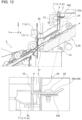
- the positioning guide 17 is located upstream of the positioner 11 in the insertion direction P. As illustrated in FIGs. 6 and 7 , the positioning guide 17 is located above the positioner 11. Specifically, the positioning guide 17 is located between and above the two first insertion portions 9a and 9b. In FIG. 7 , portions of the recording apparatus 3 except for the joint surface 4 (4a, 4b) having the second receiving portion 15 are not illustrated for ease of explanation.
- the positioners 11 are located with the inlet portion 35 being therebetween in the width direction (X-axis direction) of the medium S to be transported.
- the two first insertion portions 9a and 9b of the positioner 11 are located at respective ends of the relay unit 39 in the width direction (X-axis direction).
- the inlet portion 35 is out of sight and not illustrated, but the inlet portion 35 illustrated in FIG. 6 is located between the first insertion portions 9a and 9b in FIG. 7 .
- the two first receiving portions 10a and 10b of the positioner 11 are included in the joint surface 4 of the recording apparatus 3 at positions corresponding to the two first insertion portions 9a and 9b.
- the positioning guide 17 is located above the inlet portion 35.
- the positioning guide 17 includes a first hole 41, which is the second receiving portion 15, in the recording apparatus 3 and a first projection 43, which is the second insertion portion 13 to be inserted into the first hole 41 in the relay unit 39, which is the optional unit 5.
- the movement of the relay unit 39 in the vertical direction (Z-axis direction) is limited when the first projection 43 is inserted into the first hole 41.
- the joint surface 4 (4a, 4b) of the recording apparatus 3 is formed of a sheet metal 22 that was bent and cut.
- the first hole 41, which is the second receiving portion 15, is a cutout in the sheet metal 22.
- the holes 21a and 21b, which are the first receiving portions 10a and 10b of the positioner 11, are through holes in the sheet metal 22 as illustrated. In this embodiment, the hole 21a is long in the X-axis direction.
- the first hole 41 has a first flat portion 45.
- the first flat portion 45 is a portion of the sheet metal 22 cut and bent up into the illustrated shape to protrude in the insertion direction P.
- the first flat portion 45 has a flat surface 47 extending in the insertion direction P.
- the flat surface 47 faces the lower surface of the first projection 43 inserted into the first hole 41.
- the first flat portion 45 limits the downward movement of the first projection 43 inserted into the first hole 41.
- the second joint surface 2b which is a portion of the joint surface 2 of the relay unit 39, is formed of the sheet metal 24 that was bent and cut.
- the first projection 43 which is the second insertion portion 13, is a portion of the sheet metal 24 cut and bent up. Specifically, the first projection 43 is a portion of the sheet metal 24 cut and bent up into the illustrated shape to protrude in the insertion direction P.
- the relay unit 39 is not illustrated except for the second joint surface 2b.
- the second joint surface 2a which has the first insertion portions 9a and 9b, is also included in a different member than the sheet metal 24 and thus is not illustrated.
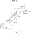
- this embodiment includes the second projections 49a and 49b, which are located with the first hole 41 at the middle being therebetween in the width direction (X-axis direction) of the medium S ( FIG. 8 ), and the second holes 51a and 51b that receive the second projections 49a and 49b ( FIG. 9 ).
- the second projections 49a and 49b are portions of the sheet metal 22, which has the first flat portion 45, cut and bent up to protrude in the direction (-Y direction) opposite the insertion direction P.
- the second holes 51a and 51b are portions of the sheet metal 24, which has the second insertion portion 13, cut and bent up to protrude in the direction (-Y direction) opposite the insertion direction P.
- the rotation of the optional unit 5 about the second insertion portion 13 is limited when the second projections 49a and 49b are inserted into the second holes 51a and 51b.
- the second projections 49a and 49b are the additional second insertion portions 13 of the positioning guide 17, and the second holes 51a and 51b are the additional second receiving portions 15 of the positioning guide 17.
- the upward movement of the optional unit 5 is limited when the second projections 49a and 49b are inserted into the second holes 51a and 51b.
- the optional unit 5 has the second holes 51a and 51b having the second flat portions 53a and 53b, respectively ( FIG. 9 ), and the second projections 49a and 49b having the plate-like third flat portions 55a and 55b, respectively ( FIG. 8 ).
- the second flat portions 53a and 53b are portions of the sheet metal 24, which has the second insertion portion 13, cut and bent up to protrude in the direction (-Y direction) opposite the insertion direction P.
- the third flat portions 55a and 55b are portions of the sheet metal 22 having the first flat portion 45 cut and bent up to protrude in the direction (-Y direction) opposite the insertion direction P. As illustrated in FIGs.
- the second flat portions 53a and 53b overlap the third flat portions 55a and 55b from below.
- the second flat portions 53a and 53b are positioned under the third flat portions 55a and 55b and overlap the third flat portions 55a and 55b in top view.
- the second flat portions 53a and 53b are in contact with the lower surfaces of the third flat portions 55a and 55b.
- the second flat portions 53a and 53b and the third flat portions 55a and 55b are fastened with screws 26 in the above-described overlapping state.
- the recording apparatus 3 includes a discharge portion 57 that discharges the medium S.
- the discharge portion 57 is configured to be inserted into the inlet portion 35.
- the first receiving portion 10 is located on the same plane as the discharge portion 57.
- the first receiving portion 10 is located at an upper position, and the discharge portion 57 is located at a lower position.
- the phrase "located on the same plane" referred to herein should not be interpreted to be "the same” in a strict sense of the word and means that the first receiving portion 10 and the discharge portion 57 are located close to one reference plane.
- the relay unit 39 further includes a rear portion 61 that has a delivery portion 59 from which the medium S is delivered to a post-processing device 37.
- the recording apparatus 3 includes a restriction portion 63 that limits the movement of the relay unit 37 in the insertion direction P.
- the movement of the rear portion 61 in the insertion direction P is limited by the restriction portion 63.
- the rear portion 61 is in contact with the outer surface of restriction portion 63. In other words, the rear portion 61 is located rearwardly from the restriction portion 63 in the insertion direction P and is in contact with the restriction portion 63.
- the rear portion 61 of the relay unit 37 is positioned by a rear positioner 68 to be in contact with the restriction portion 63 of the recording apparatus 3.
- the rear positioner 68 positions the rear portion 61 of the relay unit 37 relative to the recording apparatus 3 when two projections 65a and 65b of the restriction portion 63 are inserted into holes 67a and 67b in the rear portion 61.
- the rear portion 61 is fastened with screws 70, for example, while being correctly positioned by the rear positioner 68.
- the processing system 1 basically has the above-described configuration of the above embodiment, but the components may be partially modified or eliminated, for example, without departing from the gist of the present disclosure.
- the optional unit 5 is the relay unit 39 but may be an inner finisher.
- the inner finisher performs alignment after receiving media in the apparatus and thus requires a lower level of positioning accuracy than the relay unit 39.
- the alignment of the media recorded by an ink jet printer may be difficult due to a frictional force between the media.
- the second projections 49a and 49b and the second flat portions 53a and 53b protrude in the direction opposite the insertion direction P but may protrude in the insertion direction P.
- the joint surface 2 and the joint surface 4 may be portions of the relay unit and the recording apparatus or may be separate components that are detachable as necessary.
- the scanner 16 illustrated in FIG. 5 may be configured to be detached by being lifted up. This enables the positioning guide 17 to be seen from above during work. In particular, even when the scanner 16 covers the entire upper surface of the inner output portion 33, the lifting up of the scanner 16 enables the positioning guide 17 to be seen during work. At this time, the positioning guide 17, which is the first component to be aligned, is more visible, because the positioning guide 17 is located above the inlet portion 35 and the positioner 11, resulting in easier alignment.
Landscapes
- Physics & Mathematics (AREA)
- General Physics & Mathematics (AREA)
- Engineering & Computer Science (AREA)
- Textile Engineering (AREA)
- Automatic Assembly (AREA)
- Handling Of Cut Paper (AREA)
- Accessory Devices And Overall Control Thereof (AREA)
- Electrophotography Configuration And Component (AREA)
Applications Claiming Priority (1)
| Application Number | Priority Date | Filing Date | Title |
|---|---|---|---|
| JP2022037786A JP2023132450A (ja) | 2022-03-11 | 2022-03-11 | 処理システム及び中継搬送ユニット |
Publications (1)
| Publication Number | Publication Date |
|---|---|
| EP4242007A1 true EP4242007A1 (fr) | 2023-09-13 |
Family
ID=85571316
Family Applications (1)
| Application Number | Title | Priority Date | Filing Date |
|---|---|---|---|
| EP23161280.5A Pending EP4242007A1 (fr) | 2022-03-11 | 2023-03-10 | Système de traitement et unité de relais |
Country Status (4)
| Country | Link |
|---|---|
| US (1) | US12174580B2 (fr) |
| EP (1) | EP4242007A1 (fr) |
| JP (1) | JP2023132450A (fr) |
| CN (1) | CN116730081A (fr) |
Citations (9)
| Publication number | Priority date | Publication date | Assignee | Title |
|---|---|---|---|---|
| US5943085A (en) * | 1997-04-15 | 1999-08-24 | Brother Kogyo Kabushiki Kaisha | Image recording device having detachable web roll cassette |
| US20030071874A1 (en) * | 2000-01-21 | 2003-04-17 | Taku Ishizawa | Ink Cartridge for use with Recording Apparatus and Ink Jet Recording Apparatus |
| US6712003B2 (en) * | 2001-09-26 | 2004-03-30 | Fuji Photo Film Co., Ltd. | Sheet member positioning device and image recording device |
| EP1815994A2 (fr) * | 2003-08-08 | 2007-08-08 | Seiko Epson Corporation | Conteneur de liquide |
| US9042745B2 (en) * | 2011-01-20 | 2015-05-26 | Ricoh Company, Ltd. | Developer amount detector, image forming apparatus incorporating same, and positioning structure for positioning unit within image forming apparatus |
| US9233543B2 (en) * | 2014-04-30 | 2016-01-12 | Seiko Epson Corporation | Waste liquid container, attachment, waste liquid collection unit, and liquid ejecting apparatus |
| JP2016133635A (ja) | 2015-01-20 | 2016-07-25 | シャープ株式会社 | 画像形成装置および画像形成システム |
| US20200354182A1 (en) * | 2019-05-07 | 2020-11-12 | Kyocera Document Solutions Inc. | Relay conveyance device, image forming system, combination of image forming system, and sheet conveyance device |
| JP2022037786A (ja) | 2020-08-25 | 2022-03-09 | 大成建設株式会社 | 切羽前方の地山性状評価方法と地山性状評価システム |
Family Cites Families (16)
| Publication number | Priority date | Publication date | Assignee | Title |
|---|---|---|---|---|
| JP3366522B2 (ja) * | 1996-03-16 | 2003-01-14 | 京セラミタ株式会社 | 画像形成装置の位置決め機構 |
| JP2002019135A (ja) * | 2000-07-04 | 2002-01-23 | Seiko Epson Corp | 記録装置用インクカートリッジおよびインクジェット式記録装置 |
| JP4221754B2 (ja) * | 2001-05-10 | 2009-02-12 | 村田機械株式会社 | 画像形成装置及びその組付方法 |
| JP2003023746A (ja) * | 2001-07-04 | 2003-01-24 | Mitsuba Corp | ブラシホルダユニット |
| JP4340408B2 (ja) * | 2001-09-26 | 2009-10-07 | 富士フイルム株式会社 | シート材位置決め装置 |
| JP4228102B2 (ja) * | 2004-01-27 | 2009-02-25 | 株式会社リコー | 画像形成装置 |
| JP4706247B2 (ja) * | 2004-06-30 | 2011-06-22 | セイコーエプソン株式会社 | 液体容器 |
| JP5333059B2 (ja) * | 2009-08-27 | 2013-11-06 | ブラザー工業株式会社 | 画像記録装置 |
| JP2012032741A (ja) * | 2010-08-03 | 2012-02-16 | Ricoh Co Ltd | トナー補給装置、及び、画像形成装置 |
| JP5675709B2 (ja) * | 2012-06-15 | 2015-02-25 | 京セラドキュメントソリューションズ株式会社 | シート搬送装置及び画像形成装置 |
| TWI654098B (zh) * | 2014-03-24 | 2019-03-21 | 日商精工愛普生股份有限公司 | Belt printing device and tape printing system |
| JP6349929B2 (ja) * | 2014-04-30 | 2018-07-04 | セイコーエプソン株式会社 | 廃液収容体及び液体噴射装置 |
| JP2016172411A (ja) * | 2015-03-18 | 2016-09-29 | セイコーエプソン株式会社 | 印刷装置および印刷方法 |
| JP6403021B2 (ja) * | 2015-03-27 | 2018-10-10 | 京セラドキュメントソリューションズ株式会社 | 画像形成装置 |
| JP2022043617A (ja) * | 2020-09-04 | 2022-03-16 | キヤノン株式会社 | 画像形成装置の金属フレームの製造方法 |
| JP7000530B2 (ja) | 2020-10-29 | 2022-01-19 | キヤノンファインテックニスカ株式会社 | シート処理装置及び画像形成システム |
-
2022
- 2022-03-11 JP JP2022037786A patent/JP2023132450A/ja active Pending
-
2023
- 2023-03-09 US US18/181,266 patent/US12174580B2/en active Active
- 2023-03-10 CN CN202310232944.0A patent/CN116730081A/zh active Pending
- 2023-03-10 EP EP23161280.5A patent/EP4242007A1/fr active Pending
Patent Citations (9)
| Publication number | Priority date | Publication date | Assignee | Title |
|---|---|---|---|---|
| US5943085A (en) * | 1997-04-15 | 1999-08-24 | Brother Kogyo Kabushiki Kaisha | Image recording device having detachable web roll cassette |
| US20030071874A1 (en) * | 2000-01-21 | 2003-04-17 | Taku Ishizawa | Ink Cartridge for use with Recording Apparatus and Ink Jet Recording Apparatus |
| US6712003B2 (en) * | 2001-09-26 | 2004-03-30 | Fuji Photo Film Co., Ltd. | Sheet member positioning device and image recording device |
| EP1815994A2 (fr) * | 2003-08-08 | 2007-08-08 | Seiko Epson Corporation | Conteneur de liquide |
| US9042745B2 (en) * | 2011-01-20 | 2015-05-26 | Ricoh Company, Ltd. | Developer amount detector, image forming apparatus incorporating same, and positioning structure for positioning unit within image forming apparatus |
| US9233543B2 (en) * | 2014-04-30 | 2016-01-12 | Seiko Epson Corporation | Waste liquid container, attachment, waste liquid collection unit, and liquid ejecting apparatus |
| JP2016133635A (ja) | 2015-01-20 | 2016-07-25 | シャープ株式会社 | 画像形成装置および画像形成システム |
| US20200354182A1 (en) * | 2019-05-07 | 2020-11-12 | Kyocera Document Solutions Inc. | Relay conveyance device, image forming system, combination of image forming system, and sheet conveyance device |
| JP2022037786A (ja) | 2020-08-25 | 2022-03-09 | 大成建設株式会社 | 切羽前方の地山性状評価方法と地山性状評価システム |
Also Published As
| Publication number | Publication date |
|---|---|
| US20230288864A1 (en) | 2023-09-14 |
| CN116730081A (zh) | 2023-09-12 |
| JP2023132450A (ja) | 2023-09-22 |
| US12174580B2 (en) | 2024-12-24 |
Similar Documents
| Publication | Publication Date | Title |
|---|---|---|
| US10532594B2 (en) | Recording apparatus | |
| EP4242007A1 (fr) | Système de traitement et unité de relais | |
| US20240343051A1 (en) | Recording system | |
| JP2004106973A (ja) | 給紙カセット及び給紙装置 | |
| US11427428B2 (en) | Medium discharging device, post-processing device and recording apparatus | |
| JP2021079601A (ja) | 媒体搬送装置及び処理装置 | |
| CN109729726B (zh) | 组合壳体和图像形成装置 | |
| US20220063952A1 (en) | Stapling device of paper finishing device | |
| US12180020B2 (en) | Image processing apparatus | |
| US20220203729A1 (en) | Frame coupling structure and recording device | |
| US20240190148A1 (en) | Printing device | |
| US12589961B2 (en) | Medium transport apparatus, medium processing apparatus, and recording apparatus | |
| JP7039878B2 (ja) | 印刷装置 | |
| US20180339534A1 (en) | Transport apparatus and printing apparatus | |
| US7562974B2 (en) | Image recording apparatus and sheet material transporting apparatus | |
| US11667140B2 (en) | Printing system, reading apparatus, and holding apparatus for reading apparatus | |
| CN113247654B (zh) | 印刷装置以及印刷装置的控制方法 | |
| US20250365377A1 (en) | Medium transport device and image reading device | |
| JP2021047323A (ja) | 媒体搬送装置、後処理装置、及び記録装置 | |
| JP2728767B2 (ja) | プリンタ | |
| JP6659106B2 (ja) | 切断装置およびプリント装置 | |
| JP2005255403A (ja) | 用紙トレイ | |
| JPH0712992Y2 (ja) | プリンターのペーパーガイド部材付きペーパーマスク | |
| JP2002036648A (ja) | 記録装置における被記録材案内部材の移動規制装置及び該装置を備える記録装置 | |
| JP2024037591A (ja) | キャリッジ装置及び記録装置 |
Legal Events
| Date | Code | Title | Description |
|---|---|---|---|
| PUAI | Public reference made under article 153(3) epc to a published international application that has entered the european phase |
Free format text: ORIGINAL CODE: 0009012 |
|
| STAA | Information on the status of an ep patent application or granted ep patent |
Free format text: STATUS: THE APPLICATION HAS BEEN PUBLISHED |
|
| AK | Designated contracting states |
Kind code of ref document: A1 Designated state(s): AL AT BE BG CH CY CZ DE DK EE ES FI FR GB GR HR HU IE IS IT LI LT LU LV MC ME MK MT NL NO PL PT RO RS SE SI SK SM TR |
|
| STAA | Information on the status of an ep patent application or granted ep patent |
Free format text: STATUS: REQUEST FOR EXAMINATION WAS MADE |
|
| 17P | Request for examination filed |
Effective date: 20240223 |
|
| RBV | Designated contracting states (corrected) |
Designated state(s): AL AT BE BG CH CY CZ DE DK EE ES FI FR GB GR HR HU IE IS IT LI LT LU LV MC ME MK MT NL NO PL PT RO RS SE SI SK SM TR |
|
| STAA | Information on the status of an ep patent application or granted ep patent |
Free format text: STATUS: EXAMINATION IS IN PROGRESS |
|
| 17Q | First examination report despatched |
Effective date: 20241205 |