EP4242115B1 - Unité d'éjection - Google Patents
Unité d'éjection Download PDFInfo
- Publication number
- EP4242115B1 EP4242115B1 EP22161287.2A EP22161287A EP4242115B1 EP 4242115 B1 EP4242115 B1 EP 4242115B1 EP 22161287 A EP22161287 A EP 22161287A EP 4242115 B1 EP4242115 B1 EP 4242115B1
- Authority
- EP
- European Patent Office
- Prior art keywords
- ejection
- door
- ejection unit
- unit according
- carriage
- Prior art date
- Legal status (The legal status is an assumption and is not a legal conclusion. Google has not performed a legal analysis and makes no representation as to the accuracy of the status listed.)
- Active
Links
Images


Classifications
-
- B—PERFORMING OPERATIONS; TRANSPORTING
- B64—AIRCRAFT; AVIATION; COSMONAUTICS
- B64G—COSMONAUTICS; VEHICLES OR EQUIPMENT THEREFOR
- B64G1/00—Cosmonautic vehicles
- B64G1/22—Parts of, or equipment specially adapted for fitting in or to, cosmonautic vehicles
- B64G1/64—Systems for coupling or separating cosmonautic vehicles or parts thereof, e.g. docking arrangements
- B64G1/641—Interstage or payload connectors
-
- B—PERFORMING OPERATIONS; TRANSPORTING
- B64—AIRCRAFT; AVIATION; COSMONAUTICS
- B64G—COSMONAUTICS; VEHICLES OR EQUIPMENT THEREFOR
- B64G1/00—Cosmonautic vehicles
- B64G1/22—Parts of, or equipment specially adapted for fitting in or to, cosmonautic vehicles
-
- B—PERFORMING OPERATIONS; TRANSPORTING
- B64—AIRCRAFT; AVIATION; COSMONAUTICS
- B64G—COSMONAUTICS; VEHICLES OR EQUIPMENT THEREFOR
- B64G1/00—Cosmonautic vehicles
- B64G1/22—Parts of, or equipment specially adapted for fitting in or to, cosmonautic vehicles
- B64G1/64—Systems for coupling or separating cosmonautic vehicles or parts thereof, e.g. docking arrangements
- B64G1/641—Interstage or payload connectors
- B64G1/642—Clamps, e.g. Marman clamps
-
- B—PERFORMING OPERATIONS; TRANSPORTING
- B64—AIRCRAFT; AVIATION; COSMONAUTICS
- B64G—COSMONAUTICS; VEHICLES OR EQUIPMENT THEREFOR
- B64G1/00—Cosmonautic vehicles
- B64G1/22—Parts of, or equipment specially adapted for fitting in or to, cosmonautic vehicles
- B64G1/64—Systems for coupling or separating cosmonautic vehicles or parts thereof, e.g. docking arrangements
- B64G1/641—Interstage or payload connectors
- B64G1/643—Interstage or payload connectors for arranging multiple satellites in a single launcher
Definitions
- the present invention relates to an ejection unit according to the preamble of claim 1 for at least one cuboid-shaped satellite, in particular for at least one picosatellite, comprising a housing closed by at least one door, in which a guide is provided for receiving a satellite.
- the guide has four parallel angle rails, the two legs of which are each arranged on two (adjacent) surfaces of an (imaginary) cuboid, wherein a clamping device is provided which releasably clamps a satellite in the guide.
- Such an ejection unit is from the DE 10 2016 108 606 A1 or from the KR 102 134 620 B1
- the imaginary cuboid which is delimited by the angle rails, corresponds to the DE 10 2016 108 606 A1 in its external dimensions the external dimensions of the satellite so that it can be inserted between the angle rails.
- the satellites can be satellites according to the CubeSat standard. These are usually transported into orbit by a rocket and then ejected by the ejection unit. To eject, the door of the ejection unit is opened and the satellite(s) are pushed out of the guide and thus released. However, the satellite and the ejection unit are exposed to great acceleration and stress during transport into orbit, particularly when the rocket is launched and when rocket parts, such as a larger main satellite, are ejected.
- the clamping device has at least one tensioning mechanism which applies force to an angle rail exclusively in a direction which forms an angle bisector of this angle rail.
- a satellite is not clamped at individual discrete points, but rather via an angle rail that is part of the guide, so that the clamping force applied to the satellite is evenly distributed across the satellite. Furthermore, the clamping force is not applied to the satellite from two adjacent sides, but diagonally, which means that extraordinarily high clamping and damping forces can be achieved with just one clamping mechanism, taking into account the available installation space conditions and component dimensions. This also significantly simplifies the design.
- one of the angle rails can have a leg which extends from the adjacent surface of the (imaginary) cuboid is spaced outwards.
- one of the angle rails only rests on a satellite with one leg, with the other leg of the angle rail being spaced from the adjacent side wall of the satellite. This ensures that the associated clamping device, which exerts a force in a diagonal direction, only transfers a clamping force perpendicularly to one surface of the satellite.
- the at least one clamping mechanism can have a carriage mounted on rollers, which supports a movable guide rail, which in turn is mounted on rollers of the carriage.
- a carriage which can advantageously have an inclined guide rail, the forces for clamping the satellite can be redirected on the one hand and multiplied on the other in order to achieve improved damping.
- the carriage has two roller systems, namely one roller system for low-friction movement of the carriage and a second roller system for moving the movable guide rail.
- a spring-loaded conical bolt can be provided which, in a locking position, locks an ejection slide of the Ejection unit secures when the ejection carriage is in a pre-tensioned position. Due to a spring-loaded bolt designed as a cone at its front end, the ejection carriage can slide into a locked position by itself when the ejection carriage is tensioned, as the cone of the bolt engages in an opening in the ejection carriage. To prevent the cone bolt from being pushed out of its locked position again by the pre-tensioned ejection carriage, a further advantageous embodiment can provide a locking pin which holds the cone bolt in its locked position as long as the door is not almost completely opened.
- the at least one tensioning mechanism can have a pressure tappet that strikes the door and also a pull tappet that can be actuated by the door and that is subjected to force, for example, via a pressure rod that is articulated to the door.
- the tensioning mechanism is tensioned by two mechanisms that work independently of one another. When the door closes, it presses on the pressure tappet to activate the tensioning mechanism. At the same time, the pull tappet can apply a pulling force to the tensioning mechanism when the door is closed.
- the locking pin serves as a driver for the pull plunger at the end of the opening movement of the door, since this creates a redundant mechanism for moving the carriage in the opening direction.
- the ejection unit can have at least one rigid screw bolt that fixes an ejection carriage in a pre-tensioned position on the housing. This makes loading the satellite easier and prevents the tensioned ejection carriage from accidentally jumping forward.
- the screw bolt can be screwed into the ejection carriage from the outside through the housing, which simultaneously ensures that the carriage is at its rear stop, so that play between the ejection carriage and the housing is eliminated.
- such a screw bolt serves to prevent unwanted movements and unnecessary system loads before use in space.
- At least one fixing pin can be screwed into the door from the outside, which fixes a satellite arranged in the guide in the ejection direction without play.
- the ejection carriage can be fixed to the housing in its pre-tensioned position as described above. If the fixing pin is then screwed in from the front of the door, any play between the satellite and the housing can be eliminated.
- a plate-like anti-twist device can be provided for the fixing pin, through which the fixing pin is screwed on the one hand and which is secured on the outside of the door with a screw on the other.
- the anti-twist device When the screw is loosened, the anti-twist device can still move slightly so that the fixing pin can be screwed into the door. However, if the screw is then tightened, the anti-twist device tilts slightly so that the fixing pin can no longer be loosened due to friction in a thread of the fixing pin.
- an emergency release can be provided on the outside of the door in order to open the door manually and/or without power during test or service work.
- a door lock that can be operated without tools can be provided on the outside of the door in order to lock the door.
- the door lock can be operated with just one hand.
- the housing can be provided with service windows, each of which is closed with a plate that is inserted into a retaining groove on one side and is releasably fixed on the other side with a clamping element that is captively attached to the housing.
- the clamping element can be, for example, a nut that can be screwed onto a threaded pin, whereby the threaded pin can be provided with an end piece at its outer end that prevents the nut from being completely loosened.
- Fig. 1 shows a perspective view of an exemplary embodiment of an ejection unit for a total of four cuboid satellites.
- the ejection unit comprises a likewise cuboid-shaped housing 10 in which a total of four ejection shafts are provided, each for one satellite, which are marked with the numbers 1 to 4.
- Each ejection shaft is closed by a door 12, 14, 16 and 18, whereby the doors 12 and 14 can be pivoted about an axis A and the doors 16 and 18 can be pivoted about an axis B in order to enable a satellite to be ejected.
- Each door is closed by a locking unit (not shown in detail) which can be unlocked by remote control.
- the housing is provided with several service windows 20, each of which is closed with a plate 22.
- Each plate is inserted on one side into a retaining groove 24 formed on the housing and is releasably fixed on its opposite side with a clamping element 26 which is captively attached to the housing 10.
- the clamping element is a nut that is screwed onto a threaded pin that is provided with a cap 28 on its top to prevent the nut from coming loose.
- Each plate 22 is flexible and has a recess in the area of the clamping element that is open to the outside on one side, so that each plate 22 can be inserted under the nut 26 after being inserted into the retaining groove 24 and then screwed on.
- Fig. 1 It can also be seen that two fixing pins 30 are screwed into each door from the outside, which penetrate the door and serve to fix a satellite in the ejection direction without play.
- Each fixing pin 30 is screwed through an anti-twist device which has the shape of a plate 32, whereby the plate 32 can be screwed onto the outside of the door with a screw 34.
- the screw 34 When the screw 34 is loosened, the fixing pin 30 can be screwed into the door through the plate 32.
- the screw 34 is then tightened, the plate 32 tilts within the thread of the fixing pin 30, which prevents the fixing pin from being unscrewed from the door.
- Fig. 1 further shows that a door lock is provided on the outside of each door, which is formed by two pins 36 and 38, which can be pressed together without tools using the thumb and index finger to lock each individual door.
- An emergency release 40 is also provided on the outside of each door, which can be triggered using a tool.
- a contact element 15 is provided on each door on the front of the housing 10, the two contact pins of which are short-circuited when the door is fully opened. This makes it possible to check whether the door has fully opened when the satellite is released. Magnetic switches are also attached to the housing 10, which can detect when each door has fully closed.
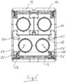
- Fig. 5 shows a top view of a part of the ejection unit of Fig. 1 , namely onto the ejection chute 4 with the door 18 open.
- a four-sided guide for the satellite is provided in the housing 10 to accommodate each satellite, which consists of a total of four angle rails 50, 52, 54 and 56, which are arranged parallel to one another, with two legs 50a, 50b, 52a, 52b, 54a, 54b and 56a, 56b being arranged on two adjacent surfaces of an (imaginary) cuboid Q, which in Fig. 5 is shown in dashed lines.
- This imaginary cuboid Q corresponds to the external dimensions of a satellite to be ejected and also extends over the length of the satellite into the plane of the drawing.
- the angle rail 54 is provided with a clamping device described in more detail below.
- This has a tensioning mechanism that applies force to the angle rail 54 exclusively in a direction W that forms an angle bisector of this angle rail. The force is therefore applied to the satellite exclusively diagonally. Since the three remaining angle rails 50, 52 and 56 are fixed to the housing 10, the satellite can be securely clamped and held in the housing 10 by applying force to the angle rail 54 in the direction of the angle bisector.
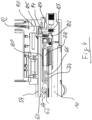
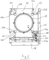
- Fig. 2 and Fig. 3 show a section along the line II-II of Fig. 1 each with open ( Fig. 2 ) and closed ( Fig. 3 ) doors.
- the angle rail 54 is attached to a sliding guide rail 60 which is mounted on rollers 62 of a carriage 64, which in turn is mounted on rollers 66 and can be moved in the ejection direction E.
- a pressure tappet 68 is used to move the carriage 64 against the ejection direction E, which strikes the back of the door when the door 18 closes and which moves the carriage 64 is displaced against the force of a spring 70 in the opposite direction to the ejection direction E.
- the rollers 62 By displacing the carriage 64 in the opposite direction to the ejection direction E, the rollers 62 move within their guide rails 72, which extend at an angle with respect to the ejection direction E and, in the embodiment shown, have a gradient of six to one. If the carriage 64 is thus moved by six units, this causes the guide rail 60 and thus also the angle profile 54 to move by one unit. Conversely, a force acting on the angle rail 54 (due to vibrations of the satellite) is reduced by a factor of six, which means that even severe vibrations can be well dampened.
- a pressure rod 74 which is connected at its front end to the door 18 via a joint 76, and which is connected at its rear end to a pull plunger 78, which pulls the slide 64 backwards against the force of a spring 80 against the ejection direction E.
- a locking pin 82 Connected to the pull plunger 78 is a locking pin 82, which can be pushed behind a spring-loaded conical bolt 84, which serves to secure an ejection slide 90, as will be described in more detail below.
- Fig. 5 shows how Fig. 5 shows, the ejection carriage 90 runs on all four angle rails 50 to 56, whereby an ejection spring 92 can cause the satellite to be ejected.
- the conical bolt 84 which is provided with a cone on its front side, engages in a corresponding recess 85 in the ejection carriage 90.
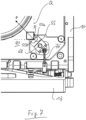
- Fig. 4 This shows a position of the ejection carriage 90 in which the latter has not yet been completely moved into its rear end position (see also Fig. 2 ). However, if this is the case ( Fig.
- the conical bolt 84 secures the ejection slide 90 in the locking position of the conical bolt 84 by pushing it into the recess 85 of the ejection carriage 90 is pressed. Due to the conical shape of the conical bolt 84, the ejection carriage 90 can initially slide over the conical bolt 84 until it engages in the recess 85. In order to prevent the conical bolt 84 from being released from its locked position, the conical bolt 84 is blocked at its rear end by the locking pin 82 as long as the door 18 is not completely or almost completely opened. Only when the door 18 has reached its open position has the pressure rod 74 moved far enough in the ejection direction E to release the conical bolt 84 at its rear.
- the force of the ejection spring 92 causes the ejection carriage 90 to move in the ejection direction E so that a satellite located on the angle rails can be ejected.
- the locking pin 82 also serves as a driver for the pull rod 78, ie the locking pin 82 presses from behind on the pull rod 78, so that the latter is forced to move in the ejection direction E if the force of a compression spring 94 ( Fig. 4 ) is not sufficient to move the carriage 64 in the ejection direction E.
- the ejection carriage 90 To load a satellite into an ejection slot of the ejection unit described above, the ejection carriage 90 is first moved against the ejection direction E to the rear end of the ejection slot so that the ejection spring 92 is compressed. In this position, the ejection carriage can then be fixed to the housing 10 in the pre-tensioned position using spring-loaded screw bolts by sliding the ejection carriage 90 over the spring-loaded screw bolt until it engages in a fixing opening. As a result, it is no longer necessary to hold the ejection carriage 90 manually in its pre-tensioned position.
- one or more screw bolts can be screwed through the housing into the ejection carriage 90 in order to fix the ejection carriage 90 in its rearmost position, which at the same time provides a transport lock.
- the Satellite is inserted into the ejection shaft, whereby it is pushed with its four outer edges into each angle rail 50 to 56.
- the door 18 is then closed, its inner side presses against the pressure tappet 68 and against the force of the spring 70, whereby the carriage 64 is moved backwards against the ejection direction E, which in turn moves the guide rail 60 due to the inclined guide rails in the direction W ( Fig. 5 ).
- the pressure rod 74 is pushed backwards via the joint 76, whereby the slide 64 is pressed backwards against the force of the spring 80 until the locking pin 82 engages behind the conical bolt 84.
- the satellite is pressed by the force of the springs 70 and 80 from the angle rail 54 against the angle rails 50, 52 and 56. If the satellite exerts a force on the angle rail 54 and thus also on the guide bar 60 due to acceleration after the rocket has been launched, this force is diverted via the 6:1 gradient to the carriage 64, which travels six times as far as the guide bar 60.
- the movement of the carriage 64 is dampened by the two springs 70 and 80. If these have a maximum force of 200 N, for example, this means that the damping system dampens the satellite with 2400 N.
- the door is unlocked by remote control so that it opens via springs (not shown in detail). This releases the pressure tappet 68 again and the pressure rod 74 begins to move forward in the ejection direction E when the door is opened, which also moves the pull tappet 78 in the ejection direction E. As soon as the two springs 70 and 80 no longer exert any force on the slide 64, the latter is pushed forward in the ejection direction E by the pressure spring 94 and this movement causes the slide bar 60 to be retracted via the inclined guide rails 72, whereby the satellite is no longer clamped in its guide.
- the locking pin 82 is positively pulled out behind the conical bolt 84 by the pressure rod 74 so that it can be pushed away from the ejection carriage 90, whereby the ejection carriage 90 is moved in the ejection direction E by the ejection spring 92 so that the satellite is ejected.
- Fig. 6 and Fig. 7 show a further embodiment of an ejection unit, wherein the same components are provided with the same reference numerals and only the differences are explained.
- the ejection unit shown has a total of three ejection shafts which can be closed by doors 12, 13 and 14, whereby the lower ejection shaft, which can be closed by door 13, has twice the volume of an upper ejection shaft.
- the two upper ejection shafts with doors 12 and 14 are designed as in the embodiment described above.
- the lower ejection shaft with door 13 in turn has two stationary angle rails 50 and 52 and an angle rail 54 which is provided with a tensioning mechanism of the type described above.
- the fourth angle rail 55 which is located on the same lower side of the cuboid Q as the angle rail 54, is also provided with a tensioning mechanism of the type described above.
- the design of the angle rail 55 differs from that of the angle rail 54, which can be seen with reference to Fig. 7 is explained in more detail.
- the angle rail 55 also has two legs 55a and 55b running at right angles to each other, whereby the leg 55b (horizontal in the figure) is again arranged on the lower surface of the cuboid Q.
- the other leg 55a (vertical in the figure) of the angle rail 55 is spaced outwards from its adjacent surface of the cuboid Q by a distance D.
- the angle rail 55 does not rest with its leg 55a on a satellite that fills the space of the cuboid Q.
- the tensioning mechanism of the angle rail 55 thus exerts a force F that is parallel to the bisector of the angle rail 55.
- this force F only acts in the vertical direction on a satellite inserted into the ejection shaft, since the leg 55a is spaced apart from the cuboid Q by the distance D and thus does not touch the satellite.
- a satellite in the ejection shaft can be strongly dampened and held well due to the two clamping mechanisms on the angle rails 54 and 55, but without the two clamping mechanisms working against each other.
Landscapes
- Engineering & Computer Science (AREA)
- Remote Sensing (AREA)
- Aviation & Aerospace Engineering (AREA)
- Mechanical Engineering (AREA)
- Physics & Mathematics (AREA)
- General Physics & Mathematics (AREA)
- Astronomy & Astrophysics (AREA)
- Casings For Electric Apparatus (AREA)
- Investigating Or Analyzing Materials By The Use Of Magnetic Means (AREA)
- Sampling And Sample Adjustment (AREA)
- Support Devices For Sliding Doors (AREA)
- Lock And Its Accessories (AREA)
- Electric Cable Installation (AREA)
- Aerials With Secondary Devices (AREA)
Claims (15)
- Ensemble d'éjection pour au moins un satellite parallélépipédique, comprenant un boîtier (10) fermé par au moins une porte (12-18), dans lequel est prévu un guidage de réception d'un satellite, qui comprend quatre cornières parallèles (50-56) dont les deux ailes (52a-54b, 55b, 56a, 56b) sont disposées respectivement sur deux faces d'un parallélépipède (Q), et un dispositif de serrage qui serre de manière amovible un satellite dans le guidage, dans lequel
le dispositif de serrage comporte au moins un mécanisme de précontrainte qui exerce une force sur l'une des cornières (54) exclusivement dans une direction (W) qui forme une bissectrice de cette cornière (54). - Ensemble d'éjection selon la revendication 1,
dans lequel
l'une des cornières (55) présente une aile (55a) qui est espacée de la face voisine du parallélépipède (Q) d'une certaine distance (D) vers l'extérieur. - Ensemble d'éjection selon la revendication 1 ou 2,
dans lequel
deux ou trois desdites cornières sont fixées de manière stationnaire au boîtier (10). - Ensemble d'éjection selon l'une des revendications précédentes,
dans lequel
ledit au moins un mécanisme de précontrainte comprend un chariot (64) monté sur des galets (62), qui supporte une barre de coulisse (60) mobile montée sur des galets (66) du chariot (64). - Ensemble d'éjection selon l'une des revendications précédentes,
dans lequel
il est prévu un boulon conique (84) sollicité par ressort, qui bloque un chariot d'éjection (90) dans une position de blocage lorsque celui-ci se trouve dans une position sous précontrainte. - Ensemble d'éjection selon la revendication 5,
dans lequel
le boulon conique (84) est maintenu dans sa position de blocage par un tourillon de verrouillage (82) tant que la porte (12-18) n'est pas presque entièrement ouverte. - Ensemble d'éjection selon l'une des revendications précédentes,
dans lequel
ledit au moins un mécanisme de précontrainte comporte un piston de pression (68) en butée contre la porte (12-18) et un piston de traction (78) actionnable par la porte (12-18), qui est soumis à une force par exemple par l'intermédiaire d'une tige de pression (74) reliée de manière articulée à la porte (12-18). - Ensemble d'éjection selon les revendications 6 et 7,
dans lequel
à la fin du mouvement d'ouverture de la porte (12-18), le tourillon de verrouillage (82) sert d'entraîneur pour le piston de traction (78). - Ensemble d'éjection selon l'une des revendications précédentes,
dans lequel
il est prévu au moins un boulon fileté rigide qui fixe un chariot d'éjection (90) au boîtier (10) dans une position sous précontrainte. - Ensemble d'éjection selon l'une des revendications précédentes,
dans lequel
il est prévu au moins un boulon fileté monté sur ressort qui fixe un chariot d'éjection (90) au boîtier (10) dans une position sous précontrainte. - Ensemble d'éjection selon l'une des revendications précédentes,
dans lequel
au moins une goupille de fixation (30) est vissée de l'extérieur dans la porte (12-18), laquelle fixe un satellite, disposé dans le guidage, sans jeu dans la direction d'éjection (E). - Ensemble d'éjection selon la revendication 11,
dans lequel
la goupille de fixation (30) est vissée à travers un dispositif anti-torsion (32) en forme de plaquette, qui est bloqué par une vis (34) sur la face extérieure de la porte (12-18). - Ensemble d'éjection selon l'une des revendications précédentes,
dans lequel
un déverrouillage d'urgence est prévu sur la face extérieure de la porte (12-18). - Ensemble d'éjection selon l'une des revendications précédentes,
dans lequel
un verrouillage de porte (36, 38) pouvant être actionné sans outil est prévu sur la face extérieure de la porte (12-18). - Ensemble d'éjection selon l'une des revendications précédentes,
dans lequel
le boîtier (10) est pourvu de fenêtres de service (20) fermées par une plaque (22) qui est insérée d'un côté dans une rainure de retenue (24) et qui est fixée de manière amovible de l'autre côté par un élément de serrage (26) fixé de manière imperdable au boîtier (10).
Priority Applications (12)
| Application Number | Priority Date | Filing Date | Title |
|---|---|---|---|
| EP22161287.2A EP4242115B1 (fr) | 2022-03-10 | 2022-03-10 | Unité d'éjection |
| ES22161287T ES3003408T3 (en) | 2022-03-10 | 2022-03-10 | Ejection unit |
| PL22161287.2T PL4242115T3 (pl) | 2022-03-10 | 2022-03-10 | Jednostka wyrzutniowa |
| US18/845,677 US12466584B2 (en) | 2022-03-10 | 2023-03-09 | Ejection unit |
| ARP230100584A AR128743A1 (es) | 2022-03-10 | 2023-03-09 | Unidad de expulsión |
| IL315462A IL315462B2 (en) | 2022-03-10 | 2023-03-09 | Ejection unit |
| KR1020247033847A KR20240170542A (ko) | 2022-03-10 | 2023-03-09 | 사출 유닛 |
| AU2023230211A AU2023230211A1 (en) | 2022-03-10 | 2023-03-09 | Ejection unit |
| JP2024553755A JP2025509398A (ja) | 2022-03-10 | 2023-03-09 | 放出ユニット |
| CA3245400A CA3245400A1 (en) | 2022-03-10 | 2023-03-09 | Ejection unit |
| PCT/EP2023/056045 WO2023170223A1 (fr) | 2022-03-10 | 2023-03-09 | Unité d'éjection |
| UY0001040177A UY40177A (es) | 2022-03-10 | 2023-03-10 | Unidad de expulsión |
Applications Claiming Priority (1)
| Application Number | Priority Date | Filing Date | Title |
|---|---|---|---|
| EP22161287.2A EP4242115B1 (fr) | 2022-03-10 | 2022-03-10 | Unité d'éjection |
Publications (3)
| Publication Number | Publication Date |
|---|---|
| EP4242115A1 EP4242115A1 (fr) | 2023-09-13 |
| EP4242115C0 EP4242115C0 (fr) | 2024-12-04 |
| EP4242115B1 true EP4242115B1 (fr) | 2024-12-04 |
Family
ID=80685554
Family Applications (1)
| Application Number | Title | Priority Date | Filing Date |
|---|---|---|---|
| EP22161287.2A Active EP4242115B1 (fr) | 2022-03-10 | 2022-03-10 | Unité d'éjection |
Country Status (12)
| Country | Link |
|---|---|
| US (1) | US12466584B2 (fr) |
| EP (1) | EP4242115B1 (fr) |
| JP (1) | JP2025509398A (fr) |
| KR (1) | KR20240170542A (fr) |
| AR (1) | AR128743A1 (fr) |
| AU (1) | AU2023230211A1 (fr) |
| CA (1) | CA3245400A1 (fr) |
| ES (1) | ES3003408T3 (fr) |
| IL (1) | IL315462B2 (fr) |
| PL (1) | PL4242115T3 (fr) |
| UY (1) | UY40177A (fr) |
| WO (1) | WO2023170223A1 (fr) |
Family Cites Families (14)
| Publication number | Priority date | Publication date | Assignee | Title |
|---|---|---|---|---|
| US5848766A (en) * | 1996-06-18 | 1998-12-15 | Spacehab, Inc. | Integrated cargo carrier for space applications |
| US8939409B2 (en) * | 2012-05-07 | 2015-01-27 | The Johns Hopkins University | Adaptor system for deploying small satellites |
| US9434486B1 (en) * | 2013-01-04 | 2016-09-06 | The United States Of America As Represented By The Administrator Of The National Aeronautics And Space Administration | System and apparatus for deploying a satellite |
| US9415883B2 (en) * | 2013-04-25 | 2016-08-16 | Planetary Systems Corporation | Canisterized satellite dispenser |
| US9845166B2 (en) * | 2014-06-04 | 2017-12-19 | Ventions, Llc | Pneumatic cubesat payload deployment system utilizing launch vehicle tank pressure |
| US9567115B2 (en) * | 2014-07-29 | 2017-02-14 | Victor Dube | Door mechanism for satellite deployer system |
| US11208218B2 (en) * | 2016-05-06 | 2021-12-28 | Xtenti, LLC | Modular and configurable spacecraft attachment and deployment assemblies |
| DE102016108606A1 (de) * | 2016-05-10 | 2017-11-16 | ECM Space Technologies GmbH | Auswurfeinheit für einen Satelliten |
| CN106081170A (zh) * | 2016-07-11 | 2016-11-09 | 上海宇航系统工程研究所 | 星箭连接分离机构 |
| US10370124B2 (en) * | 2016-10-22 | 2019-08-06 | Quad-M, Inc. | Satellite deployer spring method, system, and apparatus utilizing a bore conforming hinged leaf spring construction |
| US11066192B2 (en) * | 2017-08-04 | 2021-07-20 | Rocket Lab Usa, Inc. | Satellite deployer door with clutch bearing |
| US10538341B1 (en) * | 2018-07-06 | 2020-01-21 | Vector Launch Inc. | Self-mating modular satellite bus |
| KR102134620B1 (ko) * | 2018-10-25 | 2020-07-16 | 한국항공우주연구원 | 진동 저감 기능을 갖는 위성 발사체 및 이를 이용한 발사 방법 |
| CN109229433B (zh) * | 2018-10-29 | 2020-04-28 | 浙江大学 | 一种皮卫星星箭固定及分离装置 |
-
2022
- 2022-03-10 PL PL22161287.2T patent/PL4242115T3/pl unknown
- 2022-03-10 EP EP22161287.2A patent/EP4242115B1/fr active Active
- 2022-03-10 ES ES22161287T patent/ES3003408T3/es active Active
-
2023
- 2023-03-09 US US18/845,677 patent/US12466584B2/en active Active
- 2023-03-09 KR KR1020247033847A patent/KR20240170542A/ko active Pending
- 2023-03-09 AR ARP230100584A patent/AR128743A1/es unknown
- 2023-03-09 JP JP2024553755A patent/JP2025509398A/ja active Pending
- 2023-03-09 IL IL315462A patent/IL315462B2/en unknown
- 2023-03-09 AU AU2023230211A patent/AU2023230211A1/en active Pending
- 2023-03-09 WO PCT/EP2023/056045 patent/WO2023170223A1/fr not_active Ceased
- 2023-03-09 CA CA3245400A patent/CA3245400A1/en active Pending
- 2023-03-10 UY UY0001040177A patent/UY40177A/es unknown
Also Published As
| Publication number | Publication date |
|---|---|
| US12466584B2 (en) | 2025-11-11 |
| IL315462B1 (en) | 2025-10-01 |
| KR20240170542A (ko) | 2024-12-03 |
| AU2023230211A1 (en) | 2024-09-26 |
| UY40177A (es) | 2023-09-15 |
| US20250206470A1 (en) | 2025-06-26 |
| IL315462B2 (en) | 2026-02-01 |
| PL4242115T3 (pl) | 2025-06-09 |
| EP4242115A1 (fr) | 2023-09-13 |
| IL315462A (en) | 2024-11-01 |
| EP4242115C0 (fr) | 2024-12-04 |
| CA3245400A1 (en) | 2025-06-13 |
| JP2025509398A (ja) | 2025-04-11 |
| ES3003408T3 (en) | 2025-03-10 |
| AR128743A1 (es) | 2024-06-12 |
| WO2023170223A1 (fr) | 2023-09-14 |
Similar Documents
| Publication | Publication Date | Title |
|---|---|---|
| DE4439644C2 (de) | Verriegelungssystem für Beschläge von Fahrzeugsitzen mit freischwenkbarer Rückenlehne | |
| EP1707307B1 (fr) | Système de serrage rapide | |
| EP2851497B1 (fr) | Dispositif de montage réglable pour un élément coulissant et dispositif coulissant | |
| DE102016108606A1 (de) | Auswurfeinheit für einen Satelliten | |
| EP1495203B1 (fr) | Porte dotee d'un dispositif de securite | |
| DE102013111226B4 (de) | Schloss für eine Schließfachtür | |
| EP1809441B1 (fr) | Dispositif de serrage et de prehension, en particulier pince lineaire ou centrale | |
| EP4008480B1 (fr) | Dispositif de serrage | |
| EP4242115B1 (fr) | Unité d'éjection | |
| DE10040593A1 (de) | Verriegelungseinrichtung für längsverstellbare Sitze, insbesondere Kraftfahrzeugsitze | |
| EP4359256B1 (fr) | Dispositif de verrouillage de conteneur et procédé de verrouillage de conteneur | |
| DE2444021C3 (de) | Runge für Ladeplattformen von Fahrzeugen | |
| DE10336414A1 (de) | Ankersystem einer Betonwandschalung | |
| EP0568858B1 (fr) | Dispositif de verrouillage d'un piston commandé par pression, en particulier pour la commande d'une barre antirenversement d'un véhicule | |
| DE102019205552B3 (de) | Antrieb zum Öffnen und Schließen eines Flügels eines Fensters oder einer Tür | |
| DE102014218227A1 (de) | Dachträgeranordnung für ein Kraftfahrzeug | |
| DE9212296U1 (de) | Falt- oder raffbarer Vorhang | |
| EP4141313A1 (fr) | Dispositif d'arrêt, support de caméra pourvu de dispositif d'arrêt | |
| DE19627613C1 (de) | Pulverkraftbetriebenes Bolzensetzgerät | |
| DE9312687U1 (de) | Spanneinrichtung, insbesondere Kniehebelspanner | |
| DE102021122625A1 (de) | Containerverriegelungsvorrichtung sowie Containerverriegelungsverfahren | |
| DE9306539U1 (de) | Feststellvorrichtung für eine mit einem Türschließer versehene Tür | |
| DE2025396C3 (de) | Verschlußschnalle für einen Sicherheitsgurt, insbesondere von Kraftfahrzeugen | |
| DE2443444C2 (de) | Türfeststeller am unteren Rand eines Türblattes | |
| DE102004049935A1 (de) | Sicherungssystem für Container, insbesondere für Seetransporte |
Legal Events
| Date | Code | Title | Description |
|---|---|---|---|
| PUAI | Public reference made under article 153(3) epc to a published international application that has entered the european phase |
Free format text: ORIGINAL CODE: 0009012 |
|
| STAA | Information on the status of an ep patent application or granted ep patent |
Free format text: STATUS: THE APPLICATION HAS BEEN PUBLISHED |
|
| AK | Designated contracting states |
Kind code of ref document: A1 Designated state(s): AL AT BE BG CH CY CZ DE DK EE ES FI FR GB GR HR HU IE IS IT LI LT LU LV MC MK MT NL NO PL PT RO RS SE SI SK SM TR |
|
| STAA | Information on the status of an ep patent application or granted ep patent |
Free format text: STATUS: REQUEST FOR EXAMINATION WAS MADE |
|
| 17P | Request for examination filed |
Effective date: 20240307 |
|
| RBV | Designated contracting states (corrected) |
Designated state(s): AL AT BE BG CH CY CZ DE DK EE ES FI FR GB GR HR HU IE IS IT LI LT LU LV MC MK MT NL NO PL PT RO RS SE SI SK SM TR |
|
| GRAP | Despatch of communication of intention to grant a patent |
Free format text: ORIGINAL CODE: EPIDOSNIGR1 |
|
| STAA | Information on the status of an ep patent application or granted ep patent |
Free format text: STATUS: GRANT OF PATENT IS INTENDED |
|
| INTG | Intention to grant announced |
Effective date: 20240704 |
|
| GRAS | Grant fee paid |
Free format text: ORIGINAL CODE: EPIDOSNIGR3 |
|
| GRAA | (expected) grant |
Free format text: ORIGINAL CODE: 0009210 |
|
| STAA | Information on the status of an ep patent application or granted ep patent |
Free format text: STATUS: THE PATENT HAS BEEN GRANTED |
|
| AK | Designated contracting states |
Kind code of ref document: B1 Designated state(s): AL AT BE BG CH CY CZ DE DK EE ES FI FR GB GR HR HU IE IS IT LI LT LU LV MC MK MT NL NO PL PT RO RS SE SI SK SM TR |
|
| RAP4 | Party data changed (patent owner data changed or rights of a patent transferred) |
Owner name: EXOLAUNCH GMBH |
|
| REG | Reference to a national code |
Ref country code: CH Ref legal event code: EP |
|
| REG | Reference to a national code |
Ref country code: DE Ref legal event code: R096 Ref document number: 502022002272 Country of ref document: DE |
|
| REG | Reference to a national code |
Ref country code: IE Ref legal event code: FG4D Free format text: LANGUAGE OF EP DOCUMENT: GERMAN |
|
| U01 | Request for unitary effect filed |
Effective date: 20241204 |
|
| U07 | Unitary effect registered |
Designated state(s): AT BE BG DE DK EE FI FR IT LT LU LV MT NL PT RO SE SI Effective date: 20241211 |
|
| REG | Reference to a national code |
Ref country code: ES Ref legal event code: FG2A Ref document number: 3003408 Country of ref document: ES Kind code of ref document: T3 Effective date: 20250310 |
|
| REG | Reference to a national code |
Ref country code: SK Ref legal event code: T3 Ref document number: E 45784 Country of ref document: SK |
|
| PG25 | Lapsed in a contracting state [announced via postgrant information from national office to epo] |
Ref country code: HR Free format text: LAPSE BECAUSE OF FAILURE TO SUBMIT A TRANSLATION OF THE DESCRIPTION OR TO PAY THE FEE WITHIN THE PRESCRIBED TIME-LIMIT Effective date: 20241204 |
|
| PG25 | Lapsed in a contracting state [announced via postgrant information from national office to epo] |
Ref country code: RS Free format text: LAPSE BECAUSE OF FAILURE TO SUBMIT A TRANSLATION OF THE DESCRIPTION OR TO PAY THE FEE WITHIN THE PRESCRIBED TIME-LIMIT Effective date: 20250304 |
|
| REG | Reference to a national code |
Ref country code: GR Ref legal event code: EP Ref document number: 20250400484 Country of ref document: GR Effective date: 20250409 |
|
| PG25 | Lapsed in a contracting state [announced via postgrant information from national office to epo] |
Ref country code: SM Free format text: LAPSE BECAUSE OF FAILURE TO SUBMIT A TRANSLATION OF THE DESCRIPTION OR TO PAY THE FEE WITHIN THE PRESCRIBED TIME-LIMIT Effective date: 20241204 |
|
| PG25 | Lapsed in a contracting state [announced via postgrant information from national office to epo] |
Ref country code: IS Free format text: LAPSE BECAUSE OF FAILURE TO SUBMIT A TRANSLATION OF THE DESCRIPTION OR TO PAY THE FEE WITHIN THE PRESCRIBED TIME-LIMIT Effective date: 20250404 |
|
| U21 | Renewal fee for the european patent with unitary effect paid with additional fee |
Year of fee payment: 4 Effective date: 20250729 |
|
| PGFP | Annual fee paid to national office [announced via postgrant information from national office to epo] |
Ref country code: ES Payment date: 20250728 Year of fee payment: 4 |
|
| PLBE | No opposition filed within time limit |
Free format text: ORIGINAL CODE: 0009261 |
|
| STAA | Information on the status of an ep patent application or granted ep patent |
Free format text: STATUS: NO OPPOSITION FILED WITHIN TIME LIMIT |
|
| PG25 | Lapsed in a contracting state [announced via postgrant information from national office to epo] |
Ref country code: MC Free format text: LAPSE BECAUSE OF FAILURE TO SUBMIT A TRANSLATION OF THE DESCRIPTION OR TO PAY THE FEE WITHIN THE PRESCRIBED TIME-LIMIT Effective date: 20241204 |
|
| PGFP | Annual fee paid to national office [announced via postgrant information from national office to epo] |
Ref country code: GR Payment date: 20250731 Year of fee payment: 4 Ref country code: NO Payment date: 20250801 Year of fee payment: 4 |
|
| PGFP | Annual fee paid to national office [announced via postgrant information from national office to epo] |
Ref country code: TR Payment date: 20250725 Year of fee payment: 4 Ref country code: PL Payment date: 20250725 Year of fee payment: 4 |
|
| PGFP | Annual fee paid to national office [announced via postgrant information from national office to epo] |
Ref country code: CH Payment date: 20250813 Year of fee payment: 4 |
|
| PGFP | Annual fee paid to national office [announced via postgrant information from national office to epo] |
Ref country code: CZ Payment date: 20250724 Year of fee payment: 4 |
|
| PGFP | Annual fee paid to national office [announced via postgrant information from national office to epo] |
Ref country code: SK Payment date: 20250731 Year of fee payment: 4 |
|
| 26N | No opposition filed |
Effective date: 20250905 |
|
| PG25 | Lapsed in a contracting state [announced via postgrant information from national office to epo] |
Ref country code: IE Free format text: LAPSE BECAUSE OF NON-PAYMENT OF DUE FEES Effective date: 20250310 |