EP4242143A1 - Verfahren zum steuern einer transportvorrichtung und transportvorrichtung - Google Patents
Verfahren zum steuern einer transportvorrichtung und transportvorrichtung Download PDFInfo
- Publication number
- EP4242143A1 EP4242143A1 EP22382232.1A EP22382232A EP4242143A1 EP 4242143 A1 EP4242143 A1 EP 4242143A1 EP 22382232 A EP22382232 A EP 22382232A EP 4242143 A1 EP4242143 A1 EP 4242143A1
- Authority
- EP
- European Patent Office
- Prior art keywords
- conveyor
- trays
- speed
- pushers
- tray
- Prior art date
- Legal status (The legal status is an assumption and is not a legal conclusion. Google has not performed a legal analysis and makes no representation as to the accuracy of the status listed.)
- Pending
Links
Images



Classifications
-
- B—PERFORMING OPERATIONS; TRANSPORTING
- B65—CONVEYING; PACKING; STORING; HANDLING THIN OR FILAMENTARY MATERIAL
- B65G—TRANSPORT OR STORAGE DEVICES, e.g. CONVEYORS FOR LOADING OR TIPPING, SHOP CONVEYOR SYSTEMS OR PNEUMATIC TUBE CONVEYORS
- B65G47/00—Article or material-handling devices associated with conveyors; Methods employing such devices
- B65G47/22—Devices influencing the relative position or the attitude of articles during transit by conveyors
- B65G47/26—Devices influencing the relative position or the attitude of articles during transit by conveyors arranging the articles, e.g. varying spacing between individual articles
- B65G47/30—Devices influencing the relative position or the attitude of articles during transit by conveyors arranging the articles, e.g. varying spacing between individual articles during transit by a series of conveyors
- B65G47/32—Applications of transfer devices
-
- B—PERFORMING OPERATIONS; TRANSPORTING
- B65—CONVEYING; PACKING; STORING; HANDLING THIN OR FILAMENTARY MATERIAL
- B65B—MACHINES, APPARATUS OR DEVICES FOR, OR METHODS OF, PACKAGING ARTICLES OR MATERIALS; UNPACKING
- B65B35/00—Supplying, feeding, arranging or orientating articles to be packaged
- B65B35/10—Feeding, e.g. conveying, single articles
- B65B35/24—Feeding, e.g. conveying, single articles by endless belts or chains
- B65B35/243—Feeding, e.g. conveying, single articles by endless belts or chains using cooperating conveyors engaging the articles simultaneously
-
- B—PERFORMING OPERATIONS; TRANSPORTING
- B65—CONVEYING; PACKING; STORING; HANDLING THIN OR FILAMENTARY MATERIAL
- B65B—MACHINES, APPARATUS OR DEVICES FOR, OR METHODS OF, PACKAGING ARTICLES OR MATERIALS; UNPACKING
- B65B43/00—Forming, feeding, opening or setting-up containers or receptacles in association with packaging
- B65B43/42—Feeding or positioning bags, boxes, or cartons in the distended, opened, or set-up state; Feeding preformed rigid containers, e.g. tins, capsules, glass tubes, glasses, to the packaging position; Locating containers or receptacles at the filling position; Supporting containers or receptacles during the filling operation
- B65B43/52—Feeding or positioning bags, boxes, or cartons in the distended, opened, or set-up state; Feeding preformed rigid containers, e.g. tins, capsules, glass tubes, glasses, to the packaging position; Locating containers or receptacles at the filling position; Supporting containers or receptacles during the filling operation using roller-ways or endless conveyors
-
- B—PERFORMING OPERATIONS; TRANSPORTING
- B65—CONVEYING; PACKING; STORING; HANDLING THIN OR FILAMENTARY MATERIAL
- B65G—TRANSPORT OR STORAGE DEVICES, e.g. CONVEYORS FOR LOADING OR TIPPING, SHOP CONVEYOR SYSTEMS OR PNEUMATIC TUBE CONVEYORS
- B65G47/00—Article or material-handling devices associated with conveyors; Methods employing such devices
- B65G47/74—Feeding, transfer, or discharging devices of particular kinds or types
- B65G47/84—Star-shaped wheels or devices having endless travelling belts or chains, the wheels or devices being equipped with article-engaging elements
- B65G47/841—Devices having endless travelling belts or chains equipped with article-engaging elements
Definitions
- the present disclosure relates to a method for controlling a transporting device for transporting trays to a tray sealing machine according to claim 1 and a transporting device for transporting trays to a tray sealing machine according to independent claim 11.
- Transporting devices for transporting trays to a sealing machine are generally known. These comprise a transporting plane in which the trays are transported in a line along the transport direction of the trays. It is also known to transport the trays in several parallel lines arranged transverse to the transport direction of the trays.
- the transporting device usually comprises one or more conveyors. As the tray sealing machine requires the trays to be positioned at specific distances to each other so as to be reliably received in depressions in the sealing machine, fixed blocking bars between subsequent conveyors have been provided to stop movement of the trays in the transport direction, thereby achieving alignment of transversely arranged rows of trays and also adjusting the distance between subsequent trays.
- the transporting device comprises a sliding region
- moveable pushers it is known to use moveable pushers to move the trays along the sliding region.
- the method according to the invention for controlling a transporting device for transporting trays to a tray sealing machine comprising a control device, a first conveyor, a second conveyor downstream the first conveyor, a sliding region downstream the second conveyor and a pushing device arranged along the second conveyor and the sliding region and comprising at least two pushers extending transversally to a transport direction of the trays in the transporting device, comprises controlling, by a control device of the transport device, the first conveyor to move at a first speed, controlling the second conveyor to move at a second speed and controlling the pushing device so that the pushers move along the transport direction of the second conveyor and, in transport direction, a leading pusher restricts movement of a tray along at least a portion of the second conveyor and a trailing pusher moves the tray along at least a portion of the sliding region.
- the pushers may particularly be provided as push bars extending at least partially, preferably completely, over the transverse extension of the second conveyor.
- Controlling the speed of the pushers so that one pusher restricts the movement of a tray along at least a portion of the second conveyor and a trailing pusher moves the tray along at least a portion of the sliding region means that subsequently following pushers border a tray transported between them.
- physical contact to either of the pushers is not required to be present over the whole transport. There can thus also be times during transport where the tray is not in contact with at least one or both of the pushers.
- the restriction of the movement along at least a portion of the second conveyor comprises that the tray is in physical contact with the leading pusher so that it cannot move further than the leading pusher in the transport direction.
- the trailing pusher likewise gets into contact with the tray in the sliding region, thereby apply a force to the tray so as to move it along a portion of the sliding region.
- the second speed is smaller than the first speed and, optionally, a friction coefficient of the second conveyor with respect to the trays is smaller than a friction coefficient of the first conveyor with respect to the trays; or the second speed is larger than the first speed and, optionally, a friction coefficient of the second conveyor with respect to the trays is larger than a friction coefficient of the first conveyor with respect to the trays.
- the pushing device is driven by a first drive means and the second conveyor is driven by a second drive means independent from the first drive means.
- These drive means can be realized as independent drive chains or servomotors, for example. With this embodiment, it is possible to independently drive the pushing device so as to also take into account particular requirements regarding the transport of the trays within the sliding region.
- control device controls the first drive means so that a speed of the pushers intermittently changes from a third speed to a fourth speed, wherein, optionally, the third speed and/or the fourth speed is smaller than the second speed.
- the pushing device is controlled by the control device so that a speed of the pushers is equal to the second speed or wherein the speed of the pushers is smaller than the first speed and different from the second speed.
- This control of the pushing device, and particularly the movement of the pushers, can also allow for accounting for different first and second speeds of the first and second conveyors, respectively.
- trays are transported in at least two lines transverse to a transport direction of the trays in the transporting device.
- the throughput of the transporting device is thereby increased while still achieving reliable positioning of the trays.
- the trays are transported in the first conveyor in subsequent, spaced apart groups, wherein trays within a group are not actively aligned in a direction transverse to the transport direction of the trays in the first conveyor.
- the restrictions for transporting the trays in the first conveyors are thereby reduced while the necessary alignment of the trays before transferring them to the tray sealing machine is still ensured.
- a distance between subsequent groups of trays transported in the first conveyor can be smaller than the difference between a distance of two subsequent pushers and two times the extension of a tray in transport direction.
- This embodiment is particularly advantageous if the second speed is smaller than the first speed and results in reliable positioning of exactly one tray between two subsequent pushers.
- the pushers are connected to a common drive chain. With this, the complexity for driving the pushers is reduced.
- the transporting device can comprise a first drive means for driving the pushing device and a second drive means for driving the second conveyor, the first drive means and the second drive means being independent from each other and wherein, optionally, trays can be transported in at least two lines transverse to a transport direction of trays in the transporting device.
- the movement of the pushers of the pushing device can be controlled independent from the movement of the second conveyor, thereby also allowing for adjustment of the distance of the trays if need be.
- the pushers are connected to a common drive chain. With this, the pushers can be driven simultaneously.
- the above transporting device can be driven and controlled so as to realize any of the above embodiments pertaining to the method for controlling a transporting device for transporting trays to a tray sealing machine.
- Fig. 1 shows a schematic depiction of a transporting device 100 for transporting trays 130 to a tray sealing machine 180 downstream of the transporting device 100.
- the invention is not limited with respect to how the tray sealing machine 180 is actually realized.
- the trays may preferably be trays into which a product 131 (for example food or pieces of food and/or a paste or beverages or the like) has been introduced before being transported to the tray sealing machine 130.
- a product 131 for example food or pieces of food and/or a paste or beverages or the like
- the trays are either made from a plastic material or a metallic material or comprise the same and have at least a shape that is not determined by the forces of gravity.
- the trays 130 may comprise a depression in which the product is placed.
- the transporting device 100 comprises a first conveyor 101 that is adapted to convey trays 130 with a first speed V1 towards a second conveyor 102 downstream of the first conveyor 101.
- the second conveyor is adapted to transport the trays with a second speed V2 and to transfer the trays 130 to a sliding region 103 arranged downstream of the second conveyor 102 and upstream of the tray sealing machine 180.
- the trays are preferably not actively transported, but slide along the sliding region 103.
- the surface of the conveyors can comprise a plastic material and/or a metallic material, like stainless steel, so as to resist dirt and reduce the risk of growth of biological films.
- the belt can be made from rubber or another plastic material, or it can comprise a plurality of interlinked belt elements that can be moved relative to each other so as to realize a substantially uninterrupted belt. Also other realizations are possible.
- the velocities V1 of the first conveyor 101 and V2 of the second conveyor 102 can be equal to each other, but can also be different from each other. Additionally, as will be explained with respect to Figs. 3 and 4 , the material of the first conveyor and the material of the second conveyor can have different friction coefficients with respect to the material of the trays. Particularly, the friction coefficient of the first conveyor 101 (or at least the surface of the first conveyor coming into contact with the trays) can be larger or smaller than the respective friction coefficient of the second conveyor 102 (or the part of the second conveyor that comes into contact with the trays 130).
- the first conveyor 101 can be associated with a drive means 171 that drives the first conveyor 101.
- This drive means can, for example, be a servomotor or a chain drive or the like.
- the second conveyor 102 can likewise be associated with a drive means 172 for driving the second conveyor 102.
- the pushers can be moved back to the beginning of the second conveyor where, preferably, this movement is performed in a region where the pushers cannot get into contact with trays transported in both the second conveyor 102 and the sliding region 103.
- the pushers 141 and 142 may be moved back in a plane that is vertically spaced apart from the transport plane of the trays 130 in the second conveyor 102 and the sliding region 103.
- the pushing device can be associated with a drive means 174 for driving the pushing device and, particularly, the pushers 141 and 142. It can be provided that the pushing device and the second conveyor are driven by a common drive means, for example the drive means 172. Alternatively, the drive means 172 for driving the second conveyor 102 can be provided independent from the drive means 174 for driving the pushing device.
- a control unit 190 (for example a computer) can be provided that is connected to at least the drive means 172 and 174, and optionally also the drives means 171, so as to the control the movement of the second conveyor 102 and the pushing device 140, particularly the pushers 141 and 142 relative to the second conveyor 102, and optionally the movement of the first conveyor 101.
- the pushers have a distance to each other that is larger than the extension of the trays in the transport direction of the trays along the second conveyor 102.
- a tray can thus be accommodated between two subsequent pushers 141 and 142.
- first conveyor 101 and the second conveyor 102 are controlled so that trays transported in the first conveyor 101 and transferred to the second conveyor 102 are positioned between a first pusher 141 and a second pusher 142 so that the first pusher 141 (in the transport direction before the tray 130) acts a leading pusher, whereas the immediately following pusher 142 moves behind the tray 130 and acts as a trailing pusher.
- the leading pusher restricts the movement of the tray in the movement direction within the second conveyor 102 while the trailing pusher 142 moves the tray along at least a portion of the sliding region 103.
- the position at which the tray 130 is provided to the tray sealing machine is always the same, as it is determined by the movement of the second pusher irrespective of the actual position at which the tray was transferred from the first conveyor 101 to the second conveyor 102 with respect to the leading pusher 141 and the trailing pusher 142.
- the pushers may particularly be realized as bars extending over the whole width of the second conveyor 102 and the sliding region 103, respectively, transverse to the transport direction of the trays 130 in the second conveyor 102 and the sliding region.
- the trays are transported in the first conveyor 101 and the second conveyor 102 in a way that each pusher 141 and 142 acts as a trailing pusher for a first tray (seen in the transport direction of the trays along the second conveyor) and (simultaneously) acts as a leading pusher for an immediately following tray.
- each pusher 141 and 142 acts as a trailing pusher for a first tray (seen in the transport direction of the trays along the second conveyor) and (simultaneously) acts as a leading pusher for an immediately following tray.
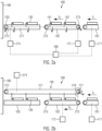
- Figs. 2a and 2b show side views on the transporting device 100 and the pushing device 140.
- the first conveyor 101 and the second conveyor 102 are depicted.
- the first conveyor is provided as an endless belt conveyor with turnaround points of the belt at positions 273 and 275.
- deflection wheels may be provided that deflect the belt.
- the pushers 141 and 142 move above the transport plane of the trays 130 within the second conveyor 102 and the sliding region 103, and are deflected at the turnaround point 272 so as to move back to the beginning of the second conveyor 102 below the transport plane of the trays 130.
- This can be realized by providing a chain drive that is driven by the drive means 172 and controlled by the control device 190.
- the drive means 172 can also be provided as part of the drive means 172 for driving the second conveyor 102.
- the turnaround point for moving the pushers into the transport plane of the trays is the turnaround point 273 and allows for moving the pushers 141 and 142 from below the transport plane into the transport plane in a region between the first conveyor 101 and the second conveyor 102.
- the arrangement of the transport mechanism 271 and the structure of the pushers is provided such that the pushers, when transported along the transport direction of the trays in the second conveyor 102 and the sliding region 103, extend into the transport plane of the trays 130 so as to potentially get into physical contact with the trays and act as leading/trailing pushers as described with respect to Fig. 1 .
- a gearing or other coupling 276 is provided between the transport mechanism 271 and the second conveyor 102 so as to translate a movement of the second conveyor into a movement of the pushers within the transport mechanism 271. This can be preferred in case there is no separate drive means 274 for driving the transport mechanism 271 of the pushing device 140.
- Figs. 2a and 2b show a movement of the pushers within the transport plane of the trays 130 and a backwards movement in a plane that is vertically spaced apart from this transport plane, it can also be provided that, at the end of the sliding region 103, the pushers are retracted and then deflected so as to be transported to the beginning of the second conveyor within the transport plane, but horizontally displaced.
- this chain can be arranged so as to move within the transport plane, but on either the left or the right side of the second conveyor and the sliding region, respectively (when seen in the direction of movement of the trays).
- the trays within one group are transported in the first conveyor 101 at a distance that is less than the difference between the distance of the pushers and the extension of the trays along the transport direction.
- FIG. 3a the situation where a tray 341 is transported in the first conveyor towards the second conveyor 102 is shown.
- a leading pusher 351 already moves along the transport direction of the trays in the transport plane of the second conveyor.
- the tray 341 is transferred from the first conveyor 101 to the second conveyor 102 while both conveyors continue their movement.
- the leading pusher 351 has also moved (compared to Fig. 3a ) along the transport direction and the leading edge of the tray 341 has a distance to the leading pusher 351 denoted with a.
- Fig. 3c time has proceeded and the first tray is now fully transported by the second conveyor 102.
- the leading edge of the tray 341 has a distance b to the leading pusher 351 which depends on the movement velocity of the pushers of the pushing device. If the pushers move faster than the speed V2, the distance b is larger than the distance a. If the pushers move slower than the speed V2, the distance b will be smaller than the distance a.
- a trailing pusher 352 has now been moved into the transport plane of the second conveyor 102 before a subsequent (second) tray 342 is transferred from the first conveyor 101 to the second conveyor 102.
- a subsequent tray 342 is moved from the second conveyor 102 in the depiction in Fig. 3d to the sliding region 103 where the second tray 342 has a distance c to the leading pusher 352 while it is not in physical contact with the trailing pusher 353.
- the distance c may be different to the size b discussed in relation to Fig. 3c and may be a consequence of imperfect alignment of trays 341 and 342 while being transported in the first conveyor 101.
- the distance between subsequent trays 341 and 342 varies, the distance to the leading and trailing pushers, respectively, in the second conveyor 102 and/or in the sliding region 103 may likewise vary.
- a tray that was, while being transported in the second conveyor 102, not in physical contact with the leading pusher 351 (i.e. was closer to the trailing pusher already) will get into contact with the trailing pusher 352 earlier compared to the just described tray.
- any tray irrespective of their relative position to the leading pusher and the trailing pusher, will be in physical contact with the trailing pusher at least at the end of the sliding region 103.
- Figs. 4a-4d show an alternative embodiment where the speed V1 of the first conveyor 101 is smaller than the speed V2 of the second conveyor 102.
- This embodiment is particularly preferred in case the friction coefficient of the second conveyor is larger than the friction coefficient of the first conveyor with respect to the material of the trays 341. With this arrangement, slip can be avoided because the second conveyor causes more force on the trays due to its larger speed and higher friction coefficient.
- a trailing pusher is moved into the transport plane so that the tray 341 is positioned between the leading pusher 351 and the trailing pusher 352.
- the leading edge of the tray 341 may have a distance b that is different from the distance a in Fig. 3b to the leading pusher 351.
- a situation similar to the situation in Fig. 3d is then obtained where, at least in one section of the sliding region 103, the trailing pusher 352 is in contact with the trailing edge of the tray 341 to the thereby actively transport the tray in the sliding region at a defined position.
- the speed of the pushers (for example a third speed) is smaller than the second speed V2 of the second conveyor 102.
- the pushers can then be moved at a fourth speed that may be larger than the second speed V2 or at least larger than the third speed so as to reduce the distance of a trailing pusher to the tray and ensure physical contact of the trailing pusher with the tray.
- a fourth speed that may be larger than the second speed V2 or at least larger than the third speed so as to reduce the distance of a trailing pusher to the tray and ensure physical contact of the trailing pusher with the tray.
Landscapes
- Engineering & Computer Science (AREA)
- Mechanical Engineering (AREA)
- Microelectronics & Electronic Packaging (AREA)
- Attitude Control For Articles On Conveyors (AREA)
Priority Applications (1)
| Application Number | Priority Date | Filing Date | Title |
|---|---|---|---|
| EP22382232.1A EP4242143A1 (de) | 2022-03-11 | 2022-03-11 | Verfahren zum steuern einer transportvorrichtung und transportvorrichtung |
Applications Claiming Priority (1)
| Application Number | Priority Date | Filing Date | Title |
|---|---|---|---|
| EP22382232.1A EP4242143A1 (de) | 2022-03-11 | 2022-03-11 | Verfahren zum steuern einer transportvorrichtung und transportvorrichtung |
Publications (1)
| Publication Number | Publication Date |
|---|---|
| EP4242143A1 true EP4242143A1 (de) | 2023-09-13 |
Family
ID=80780717
Family Applications (1)
| Application Number | Title | Priority Date | Filing Date |
|---|---|---|---|
| EP22382232.1A Pending EP4242143A1 (de) | 2022-03-11 | 2022-03-11 | Verfahren zum steuern einer transportvorrichtung und transportvorrichtung |
Country Status (1)
| Country | Link |
|---|---|
| EP (1) | EP4242143A1 (de) |
Citations (4)
| Publication number | Priority date | Publication date | Assignee | Title |
|---|---|---|---|---|
| CH523172A (de) * | 1970-05-04 | 1972-05-31 | Sig Schweiz Industrieges | Vorrichtung zur regelmässigen Abgabe von unregelmässig einlaufenden Gegenständen |
| US4815581A (en) * | 1985-06-26 | 1989-03-28 | Sig Schweizerische Industrie-Gesellschaft | Apparatus for separating items conveyed in a contacting series |
| US20050262802A1 (en) * | 2004-05-12 | 2005-12-01 | Johann Natterer | Packaging machine and method for supplying containers in a packaging machine |
| US20120198795A1 (en) * | 2011-02-08 | 2012-08-09 | Ct Pack S.R.L. | Packaging machine and method |
-
2022
- 2022-03-11 EP EP22382232.1A patent/EP4242143A1/de active Pending
Patent Citations (4)
| Publication number | Priority date | Publication date | Assignee | Title |
|---|---|---|---|---|
| CH523172A (de) * | 1970-05-04 | 1972-05-31 | Sig Schweiz Industrieges | Vorrichtung zur regelmässigen Abgabe von unregelmässig einlaufenden Gegenständen |
| US4815581A (en) * | 1985-06-26 | 1989-03-28 | Sig Schweizerische Industrie-Gesellschaft | Apparatus for separating items conveyed in a contacting series |
| US20050262802A1 (en) * | 2004-05-12 | 2005-12-01 | Johann Natterer | Packaging machine and method for supplying containers in a packaging machine |
| US20120198795A1 (en) * | 2011-02-08 | 2012-08-09 | Ct Pack S.R.L. | Packaging machine and method |
Similar Documents
| Publication | Publication Date | Title |
|---|---|---|
| US6527102B2 (en) | Installation for forming batches of articles | |
| EP0007231B1 (de) | Fördervorrichtung zum gruppenweisen Aufteilen von Gegenständen | |
| CN111655585B (zh) | 具有纸箱翻转站的连续运动包装机 | |
| EP2195265B1 (de) | Messvorrichtung und verfahren für ein übertragungsgerät | |
| EP2417029B1 (de) | Inline zuführer mit kontinuierlicher bewegung | |
| US10822175B2 (en) | Device and method for buffering piece goods | |
| KR19980703513A (ko) | 멀티 팩 포장 장치 | |
| MX2009001307A (es) | Arreglo para agrupar en filas los productos de un lote en una banda transportadora de alta velocidad. | |
| US5481848A (en) | Method for feeding and preparing information leaflets on a product packaging line and a system for implementing this method | |
| US5887701A (en) | Method and unit for forming and conveying groups of products | |
| US12459754B2 (en) | Handling device for a transfer of products, production machine with such a handling device and method for a transfer of products | |
| US7581637B2 (en) | Feeding device for a packaging machine | |
| US6168149B1 (en) | Method and unit for feeding blanks to a user machine | |
| US3982382A (en) | Article bucket with circular clamp | |
| EP4011808B1 (de) | Vorrichtung zum bewegen und gruppieren von flachen produkten | |
| CN106660711B (zh) | 用于输送块式产品的方法和装置 | |
| US4771877A (en) | Load spacing conveyor system | |
| US5309697A (en) | Chewing gum packaging machine | |
| GB1075830A (en) | Packaging apparatus | |
| NL7906965A (nl) | Stelsel voor het toevoeren van voorwerpen. | |
| JP2021014360A (ja) | 物品積み重ね装置、物品積み重ね方法、および、物品包装システム | |
| EP0632776B1 (de) | Beschickungsvorrichtung zur verwendung in kartoniereinrichtungen | |
| JP4247522B2 (ja) | 物品揃え装置 | |
| NL2032479B1 (en) | Transport system for transporting one or more products | |
| US5131523A (en) | Slide transfer |
Legal Events
| Date | Code | Title | Description |
|---|---|---|---|
| PUAI | Public reference made under article 153(3) epc to a published international application that has entered the european phase |
Free format text: ORIGINAL CODE: 0009012 |
|
| STAA | Information on the status of an ep patent application or granted ep patent |
Free format text: STATUS: THE APPLICATION HAS BEEN PUBLISHED |
|
| AK | Designated contracting states |
Kind code of ref document: A1 Designated state(s): AL AT BE BG CH CY CZ DE DK EE ES FI FR GB GR HR HU IE IS IT LI LT LU LV MC MK MT NL NO PL PT RO RS SE SI SK SM TR |
|
| STAA | Information on the status of an ep patent application or granted ep patent |
Free format text: STATUS: REQUEST FOR EXAMINATION WAS MADE |
|
| 17P | Request for examination filed |
Effective date: 20240130 |
|
| P01 | Opt-out of the competence of the unified patent court (upc) registered |
Effective date: 20240131 |
|
| RBV | Designated contracting states (corrected) |
Designated state(s): AL AT BE BG CH CY CZ DE DK EE ES FI FR GB GR HR HU IE IS IT LI LT LU LV MC MK MT NL NO PL PT RO RS SE SI SK SM TR |
|
| STAA | Information on the status of an ep patent application or granted ep patent |
Free format text: STATUS: EXAMINATION IS IN PROGRESS |
|
| 17Q | First examination report despatched |
Effective date: 20250502 |