EP4242180A2 - Verfahren zum markieren von glastafeln, vorzugsweise von einscheiben-sicherheitsglastafeln - Google Patents
Verfahren zum markieren von glastafeln, vorzugsweise von einscheiben-sicherheitsglastafeln Download PDFInfo
- Publication number
- EP4242180A2 EP4242180A2 EP23187829.9A EP23187829A EP4242180A2 EP 4242180 A2 EP4242180 A2 EP 4242180A2 EP 23187829 A EP23187829 A EP 23187829A EP 4242180 A2 EP4242180 A2 EP 4242180A2
- Authority
- EP
- European Patent Office
- Prior art keywords
- marking
- coating
- glass
- functional
- layer
- Prior art date
- Legal status (The legal status is an assumption and is not a legal conclusion. Google has not performed a legal analysis and makes no representation as to the accuracy of the status listed.)
- Granted
Links
Images

Classifications
-
- C—CHEMISTRY; METALLURGY
- C03—GLASS; MINERAL OR SLAG WOOL
- C03C—CHEMICAL COMPOSITION OF GLASSES, GLAZES OR VITREOUS ENAMELS; SURFACE TREATMENT OF GLASS; SURFACE TREATMENT OF FIBRES OR FILAMENTS MADE FROM GLASS, MINERALS OR SLAGS; JOINING GLASS TO GLASS OR OTHER MATERIALS
- C03C23/00—Other surface treatment of glass not in the form of fibres or filaments
- C03C23/0005—Other surface treatment of glass not in the form of fibres or filaments by irradiation
- C03C23/0025—Other surface treatment of glass not in the form of fibres or filaments by irradiation by a laser beam
-
- B—PERFORMING OPERATIONS; TRANSPORTING
- B41—PRINTING; LINING MACHINES; TYPEWRITERS; STAMPS
- B41M—PRINTING, DUPLICATING, MARKING, OR COPYING PROCESSES; COLOUR PRINTING
- B41M5/00—Duplicating or marking methods; Sheet materials for use therein
- B41M5/26—Thermography ; Marking by high energetic means, e.g. laser otherwise than by burning, and characterised by the material used
- B41M5/262—Thermography ; Marking by high energetic means, e.g. laser otherwise than by burning, and characterised by the material used recording or marking of inorganic surfaces or materials, e.g. glass, metal, or ceramics
-
- C—CHEMISTRY; METALLURGY
- C03—GLASS; MINERAL OR SLAG WOOL
- C03C—CHEMICAL COMPOSITION OF GLASSES, GLAZES OR VITREOUS ENAMELS; SURFACE TREATMENT OF GLASS; SURFACE TREATMENT OF FIBRES OR FILAMENTS MADE FROM GLASS, MINERALS OR SLAGS; JOINING GLASS TO GLASS OR OTHER MATERIALS
- C03C17/00—Surface treatment of glass, not in the form of fibres or filaments, by coating
- C03C17/28—Surface treatment of glass, not in the form of fibres or filaments, by coating with organic material
- C03C17/32—Surface treatment of glass, not in the form of fibres or filaments, by coating with organic material with synthetic or natural resins
-
- C—CHEMISTRY; METALLURGY
- C03—GLASS; MINERAL OR SLAG WOOL
- C03C—CHEMICAL COMPOSITION OF GLASSES, GLAZES OR VITREOUS ENAMELS; SURFACE TREATMENT OF GLASS; SURFACE TREATMENT OF FIBRES OR FILAMENTS MADE FROM GLASS, MINERALS OR SLAGS; JOINING GLASS TO GLASS OR OTHER MATERIALS
- C03C17/00—Surface treatment of glass, not in the form of fibres or filaments, by coating
- C03C17/34—Surface treatment of glass, not in the form of fibres or filaments, by coating with at least two coatings having different compositions
-
- C—CHEMISTRY; METALLURGY
- C03—GLASS; MINERAL OR SLAG WOOL
- C03C—CHEMICAL COMPOSITION OF GLASSES, GLAZES OR VITREOUS ENAMELS; SURFACE TREATMENT OF GLASS; SURFACE TREATMENT OF FIBRES OR FILAMENTS MADE FROM GLASS, MINERALS OR SLAGS; JOINING GLASS TO GLASS OR OTHER MATERIALS
- C03C17/00—Surface treatment of glass, not in the form of fibres or filaments, by coating
- C03C17/34—Surface treatment of glass, not in the form of fibres or filaments, by coating with at least two coatings having different compositions
- C03C17/36—Surface treatment of glass, not in the form of fibres or filaments, by coating with at least two coatings having different compositions at least one coating being a metal
-
- C—CHEMISTRY; METALLURGY
- C03—GLASS; MINERAL OR SLAG WOOL
- C03C—CHEMICAL COMPOSITION OF GLASSES, GLAZES OR VITREOUS ENAMELS; SURFACE TREATMENT OF GLASS; SURFACE TREATMENT OF FIBRES OR FILAMENTS MADE FROM GLASS, MINERALS OR SLAGS; JOINING GLASS TO GLASS OR OTHER MATERIALS
- C03C17/00—Surface treatment of glass, not in the form of fibres or filaments, by coating
- C03C17/34—Surface treatment of glass, not in the form of fibres or filaments, by coating with at least two coatings having different compositions
- C03C17/36—Surface treatment of glass, not in the form of fibres or filaments, by coating with at least two coatings having different compositions at least one coating being a metal
- C03C17/38—Surface treatment of glass, not in the form of fibres or filaments, by coating with at least two coatings having different compositions at least one coating being a metal at least one coating being a coating of an organic material
-
- B—PERFORMING OPERATIONS; TRANSPORTING
- B41—PRINTING; LINING MACHINES; TYPEWRITERS; STAMPS
- B41M—PRINTING, DUPLICATING, MARKING, OR COPYING PROCESSES; COLOUR PRINTING
- B41M5/00—Duplicating or marking methods; Sheet materials for use therein
- B41M5/24—Ablative recording, e.g. by burning marks; Spark recording
-
- C—CHEMISTRY; METALLURGY
- C03—GLASS; MINERAL OR SLAG WOOL
- C03C—CHEMICAL COMPOSITION OF GLASSES, GLAZES OR VITREOUS ENAMELS; SURFACE TREATMENT OF GLASS; SURFACE TREATMENT OF FIBRES OR FILAMENTS MADE FROM GLASS, MINERALS OR SLAGS; JOINING GLASS TO GLASS OR OTHER MATERIALS
- C03C2218/00—Methods for coating glass
- C03C2218/30—Aspects of methods for coating glass not covered above
- C03C2218/32—After-treatment
- C03C2218/328—Partly or completely removing a coating
-
- C—CHEMISTRY; METALLURGY
- C03—GLASS; MINERAL OR SLAG WOOL
- C03C—CHEMICAL COMPOSITION OF GLASSES, GLAZES OR VITREOUS ENAMELS; SURFACE TREATMENT OF GLASS; SURFACE TREATMENT OF FIBRES OR FILAMENTS MADE FROM GLASS, MINERALS OR SLAGS; JOINING GLASS TO GLASS OR OTHER MATERIALS
- C03C2218/00—Methods for coating glass
- C03C2218/30—Aspects of methods for coating glass not covered above
- C03C2218/355—Temporary coating
Definitions
- the present invention relates to a method for marking glass panels, preferably toughened safety glass panels.
- Flat glass refers to any glass in the form of panes or sheets, regardless of the manufacturing process used.
- the functions can be, for example, thermal protection, sun protection, or heating.
- one or more metal layers reduce the emissivity of the glass panels and serve as a heat and/or solar protection layer.
- the functional coating or functional coating is a single functional layer or a layer structure with several functional layers with a total thickness of ⁇ 2 ⁇ m.
- the layer structure is usually obtained by deposition processes, preferably sputtering.
- the individual functional layers are therefore generally metallic and/or ceramic layers.
- these are metallic low-emission layers or electrical heating layers.
- One or more dielectric (functional) layers for example made of an oxide such as aluminum oxide, can be arranged between the individual metallic functional layers of a functional coating.
- an adhesion-promoting layer made of tin oxide between the functional coating and the glass surface.
- a removable protective film temporary protective film
- a polymer protective layer e.g. EasyPro ® from St. Gobain
- the polymer protective layer is applied, for example, by spraying and cannot be removed, but is firmly bonded to the respective surface. However, it burns easily and without leaving any residue during annealing in the oven.
- the protective coating is removed before the glass panel is used as intended.
- Toughened safety glass consists of a single, specially heat-treated glass pane.
- the glass pane is heated to temperatures above its transformation temperature and then suddenly cooled again, so that a pre-stress is created in the glass pane.
- the heat treatment is preferably carried out in accordance with DIN EN 12150-1:2015-12. Due to the pre-tensioning, toughened safety glass has increased shock and impact resistance compared to normal flat glass panels.
- Toughened safety glass is subject to a legal labeling requirement, at least in Germany.
- the marking is done either with ceramic paint using a hand screen printing process or using a decal.
- the marking is applied before heat treatment in the oven and burned into the glass when tempering the glass.
- the ceramic paint requires the oven temperature to bond consistently to the surface.
- the marking is applied to the polymer protective layer in the known methods. This will result in the marking with the polymer protective layer being removed. The marking therefore disappears during heat treatment in the oven.
- toughened safety glass panels with a polymer protective layer do not currently meet the legal labeling requirement if they have been marked with hand screen printing or decal.
- a glass-like layer with metal nanoparticles is applied to the surface of the glass panel using a laser.
- a donor or carrier medium is brought into contact with the glass panel surface to be labeled and a marking is created on the glass panel surface using laser beam-induced processes.
- the carrier medium has, for example, a PET film which has, for example, a low-E functional coating, which has at least one metallic functional layer.
- marking a laser beam is directed onto the functional coating and, due to the laser beam irradiation, material from the functional coating is transferred from the PET carrier film to the glass panel surface to be marked. The material adheres to the glass panel surface as a glass-like matrix with metallic nanoparticles, the matrix being formed from the substances originally present in the functional layers of the functional coating.
- the PET carrier film remains intact.
- a method for marking glass panels without a protective layer using a laser is also known.
- a laser beam is directed onto a marking material in order to vaporize the marking material and deposit it on a specific area of the substrate to be marked.
- a second step Using a laser beam, the material deposited on the substrate to be marked is removed or converted according to the marking to be produced.
- the EP 3 031 785 A1 discloses a method for producing a glass ceramic element with a structured coating, wherein a glass ceramic element is provided with a coating that at least partially blocks light in the visible spectral range, the glass ceramic element is irradiated with a pulsed laser beam so that the coating is removed by ablation, and after removing the coating the glass ceramic is irradiated with the same laser in the area of the removed coating, so that the glass ceramic is optically modified in the irradiated area.
- the DE 102 58 522 A1 discloses a method for marking a heat-insulating laminated glass pane made of two panes of glass, at least one PVB film lying between the two panes of glass and a thin metal layer that is transparent in the visible wavelength range.
- the metal layer is exposed to a laser beam and is colored due to the effect of the laser beam.
- the object of the present invention is therefore to provide a simple and cost-effective marking method for permanently marking glass panels coated with a protective coating, preferably a protective film or a polymer protective layer, in particular ESG glass panels.
- Marking is carried out in accordance with the procedure in accordance with DE 10 2005 025 982 A1 , although according to the invention the glass panel has a protective coating.
- the protective coating is removed using laser radiation, preferably burned or burned away, and in the same operation, marking material from a donor or carrier medium is printed using the laser radiation onto an exposed surface of the glass panel, which was previously underneath the protective coating of the glass panel has found.
- marking material is applied to the outward-facing functional coating surface and/or to the glass surface.
- the marking material is applied to the uncoated glass surface.
- the protective coating is removed using laser radiation, preferably burned or burned away, and in the same operation the functional coating previously underneath is changed in color, so that due to the contrast between the color-changed areas and the non-changed areas, a marking is made in the Functional coating is produced itself.
- a glass panel 1 to be marked according to the invention has a first and second glass surface 1a; b and preferably a circumferential glass panel edge 1c.
- the glass panel 1 preferably has only a single glass pane 2 ( Fig. 1 ) on.
- Each glass pane 2 has two glass pane surfaces 2a; b. If the glass panel 1 only has a single glass pane 2, the two glass pane surfaces 2a; b form the glass surfaces 1a; b of the glass panel 1a; b.
- the glass panel 1 is an ESG glass panel with a single glass pane 2 that is still to be toughened or has already been toughened.
- the glass panel 1 can also be a composite glass panel made of several interconnected glass panes 2 (not shown).
- Composite glass panels are a laminate made of at least two individual glass panes 2, each of which is connected to one another by means of an adhesive intermediate layer made of plastic, in particular by a highly tear-resistant, viscoelastic, thermoplastic film.
- the two outer glass pane surfaces 2a; b form the glass surfaces 1a; b of the glass panel 1a; b.
- the glass panes 2 of the laminated glass panel are preferably at least partially tempered glass panes 2.
- the glass panel 1 has a surface functional coating 3 on at least one of its two glass surfaces 1a; b.
- the functional coating 3 has an outer functional coating surface 3a facing away from the glass pane(s) 2.
- the functional coating 3 can have one or more individual functional layers. If there are several functional layers, it is a functional layer laminate. The functional layers change certain properties of the glass panel 1 or give it certain functions. The functions can be, for example, thermal protection, sun protection, or heating.
- the functional coating 3 is preferably a wavelength-selective or low-E coating. The functional coating 3 is not removed before the glass panel 1 is used as intended, but is still there when the glass panel 1 is used as intended available.
- the functional coating 3 of the glass panel 1 has at least one metal-containing functional layer.
- it is preferably a metal or a, preferably ceramic, metal oxide layer.
- the metallic functional layers are preferably embedded in oxide functional layers, for example made of a metal oxide, preferably tin oxide, which increases transmission and durability.
- the functional coating 3 can have a functional layer made of, preferably ceramic, metal oxide, preferably tin oxide, which is connected directly to the glass surface 1a; b, and connects the remaining layers of the functional coating 3 to the glass surface 1a; b.
- the functional layer made of metal oxide, preferably tin oxide thus also serves as an adhesive layer.
- a metal-containing, preferably metallic, functional layer preferably has silver, copper or gold.
- a functional layer made of metal oxide preferably consists of tin oxide.
- the ceramic functional layer does not have to consist of oxide ceramic.
- it can also be a non-oxidic ceramic functional layer.
- the functional coating 3 of the glass panel 1 thus has at least one metallic and/or at least one, preferably metal-containing, ceramic functional layer.
- the functional layers are preferably applied to the glass pane 2 by sputtering or wet chemically.
- the functional coating 3 preferably has a thickness of ⁇ 2 ⁇ m, preferably ⁇ 1 ⁇ m.
- the glass panel 1 has glass on at least one of its two surfaces 1a;b a protective coating 4 in the form of a polymer protective layer or a removable protective film.
- the protective coating 4 covers the respective glass surface 1a; b and the functional coating 3 to the outside and protects in particular the functional coating 3 arranged under the protective coating 4 or, if there is no functional coating 3, the pure glass surface 1a; b, from mechanical damage.
- the protective coating 4 thus forms the outer or outer layer of the glass panel 1.
- the protective coating 4 is completely removed before the final use of the glass panel 1. It is therefore not permanent.
- the protective film is removed and the polymer protective layer is burned.
- the functional coating 3, on the other hand, is permanently present, at least in some areas.
- the polymer protective layer consists of a polymer and cannot be removed from the glass panel 1.
- the polymer protective layer is firmly or inextricably or non-destructively connected to the respective surface (functional coating surface 3a or glass surface 1a; b).
- the polymer protective layer preferably has a thickness of 1 ⁇ m to 1 mm, preferably 1 ⁇ m to 100 ⁇ m.
- the protective film is made of plastic, preferably polyvinyl chloride (PVC), and can be removed from the glass panel 1.
- PVC polyvinyl chloride
- the protective film preferably has a thickness of 20 to 100 ⁇ m.
- a mark is not created on the glass panel 1 according to the invention by printing marking material using laser radiation or according to the invention by changing the color of the functional coating 3, with the protective coating 4 being removed at the same time in the area of the marking by means of the laser radiation, preferably burned.
- Fig. 2 shows an example of a marking device 5 for implementation of the marking process not according to the invention.
- Fig. 1 shows an example of a marking device 5 for carrying out the marking method according to the invention.
- the marking device 5 has a laser beam generating device 6 for generating a laser beam 7. To carry out the method not according to the invention, the marking device 5 also has a donor or carrier medium 8, several guide rollers 9 and a pressure frame 10.
- the laser beam generating device 6 is used to remove the polymer protective layer or the protective film in the area of the marking to be produced and to produce the marking in the same operation.
- the laser beam generating device 6 generates the laser beam 7.
- the laser beam generating device 6 has a laser radiation source and associated optics.
- the laser beam 7 is focused using the optics.
- the laser beam 7 can be pivoted or deflected from a starting position in which it is aligned vertically or perpendicularly to the glass surface 1a; b.
- the laser radiation source preferably generates a laser beam 7 whose wavelength is 190 nm to 12 ⁇ m, preferably 500 nm to 2 ⁇ m.
- the laser radiation source preferably generates a laser beam 7 whose laser power is ⁇ 20 W, preferably ⁇ 10 W, and/or ⁇ 0.5 W, preferably ⁇ 5 W.
- the laser radiation source preferably generates a pulsed laser beam 7. However, it can also generate a continuous laser beam 7.
- the donor or carrier medium 8 is preferably a coated plastic film, preferably made of PET.
- the carrier medium 8 is preferably band-shaped.
- the carrier medium 8 has a surface marking coating made of marking material, which has at least one metal-containing, preferably metallic, marking layer and/or at least one ceramic marking layer.
- the metal-containing marking layer is preferably a metal or a, preferably ceramic, metal oxide layer.
- the metallic marking layers are preferably embedded in oxidic functional layers, for example made of a metal oxide, preferably tin oxide.
- the marking coating can have a marking layer made of, preferably ceramic, metal oxide, preferably tin oxide, which is connected directly to the surface of the carrier medium 8 and connects the remaining layers of the marking coating to the surface.
- the marking layer made of metal oxide, preferably tin oxide thus also serves as an adhesive layer.
- a metal-containing, preferably a metallic, marking layer has silver, copper or gold.
- the ceramic marking layer does not have to consist of oxide ceramic.
- it can also be a non-oxidic ceramic marking layer.
- the marking coating of the glass panel 1 thus has at least one metallic and/or at least one, preferably metal-containing, ceramic marking layer.
- the marking layers are preferably applied to the carrier medium 8 by sputtering or wet chemically.
- the marking coating is expediently a low-E coating.
- the marking coating preferably has a thickness of ⁇ 5 ⁇ m.
- the pressure frame 10 is used to press the band-shaped carrier medium 8 onto the glass panel 1 to be marked.
- the pressure frame 10 is preferably transparent to the laser radiation.
- the pressure frame 10 has an opening that exposes the marking area.
- the band-shaped carrier medium 8 is also guided around the guide rollers 9.
- the carrier medium 8 is now pressed onto the glass panel 1 with its side coated with the marking coating using the pressure frame 10. Then, by means of the laser beam 7 focused on the marking coating, marking material is transferred from the marking coating to the glass panel 1, in particular the functional coating surface 3a and/or the glass surface 1a; b, and fixed to it. Because the laser radiation is absorbed by the marking material, it is detached from the carrier medium 8 and transported to the surface 1a; b; 3a to be marked.
- the protective coating 4 is removed by means of the laser beam 7, in particular burned, in order to expose the surface 1a; b; 3a to be marked.
- Both the material of the pressure frame 10 and the carrier medium 8 are at most weakly absorbent at the laser wavelength of the laser beam 7, so that the laser beam 7 passes through the carrier medium 8 and the pressure frame 10.
- the glass panel 1 and the laser beam 7 and, if necessary, the carrier medium 8 must be moved relative to each other parallel to the glass surfaces 1a; b.
- the movement of the laser beam 7 is preferably carried out by means of the optics of the laser beam generating device 6.
- the optics of the laser generating device 6 is preferably able to move the laser beam 7 in a range of, for example, 100 mm x 100 mm (scan field) with the help of two adjustable mirrors (scanning optics).
- the band-shaped carrier medium 8 is then moved forward.
- the marking is therefore carried out by introducing burn marks or laser traces into the protective coating 4 and transferring marking material from the marking coating from the carrier medium 8 to the glass panel 1, in particular to the functional coating surface 3a and/or the glass surface 1a; b.
- the laser tracks can be point-shaped, line-shaped or flat.
- the protective coating 4 has been completely removed, in particular evaporated or burned, and the marking material is applied to the surface 1a; b, 3a that has become free or exposed as a result.
- marking in the method according to the invention is carried out by introducing burn marks or laser traces into the protective coating 4 and the functional coating 3.
- the protective coating 4 is completely removed, in particular evaporated or burned, and the functional coating 3 is discolored.
- the cause of the discoloration is, among other things, the absorption of the laser radiation in the metallic or ceramic functional layer. This is heated up so much by the absorption that the material of the functional coating changes in the irradiated area.
- the metal is in the form of nanoparticles, embedded in a matrix, formed at least partially from material from the other functional layers originally present in the functional coating 3.
- the chemical structure of the material is changed so that it changes color.
- ESG glass panels can also be permanently marked with a protective coating 4.
- the not yet tempered glass panels 1 can be marked and the marking remains despite the polymer coating burning away during the heat treatment. This means that test markings can also be applied, which indicate by a color change that the necessary time for the temperature treatment has been reached.
- toughened ESG glass panels can also be marked with protective film.
- the markings produced according to the invention are highly resistant to abrasion and weather influences as well as temperatures, solvents or other chemicals. This ensures optimal marking over the entire service life of the glass panel 1.
- the marking device 5 for carrying out the method according to the invention can be easily integrated into cutting and breaking lines or designed as a single-user system.
- the marking device can be integrated into the cutting bridge.
- machine-readable codes e.g. data matrix codes
- logos and product IDs, serial numbers, order-specific data can be carried out individually for each glass panel.
- the laser beam 7 can also be directed through the glass panel 1 onto the marking coating or the functional coating 3. This makes it easier to integrate laser marking into the furnace loading workflow.
- a 1 ⁇ m laser was directed onto the coated glass surface of an ESG glass panel provided with a polymer protective layer.
- the ESG glass panel also had a low-E coating with a silver layer.
- the laser power was 5 W.
- the frequency of the pulsed laser beam was 10 kHz.
- the beam diameter in focus was 100 ⁇ m.
- a permanent mark was created in the low-E coating and the polymer protective layer in the area of the mark was removed.
Landscapes
- Chemical & Material Sciences (AREA)
- Engineering & Computer Science (AREA)
- Chemical Kinetics & Catalysis (AREA)
- General Chemical & Material Sciences (AREA)
- Geochemistry & Mineralogy (AREA)
- Materials Engineering (AREA)
- Organic Chemistry (AREA)
- Life Sciences & Earth Sciences (AREA)
- Optics & Photonics (AREA)
- Physics & Mathematics (AREA)
- Ceramic Engineering (AREA)
- Health & Medical Sciences (AREA)
- Toxicology (AREA)
- Surface Treatment Of Glass (AREA)
- Laser Beam Processing (AREA)
- Joining Of Glass To Other Materials (AREA)
Abstract
Description
- Die vorliegende Erfindung betrifft ein Verfahren zum Markieren von Glastafeln, vorzugsweise von Einscheiben-Sicherheitsglastafeln.
- Als Flachglas wird jedes Glas in Form von Scheiben bzw. Tafeln bezeichnet, unabhängig vom angewandten Herstellungsverfahren. Um Flachglastafeln mit Filter-, Spiegel-, Heizfunktionen oder sonstigen Funktionen zu versehen, werden die unterschiedlichsten, ein- oder mehrlagigen Funktionsbeschichtungen auf die Flachglastafeln aufgebracht. Die Funktionen können dabei z.B. Wärmeschutz, Sonnenschutz, oder Beheizung sein. Bei Low-E-Glas (Low-E = Low-Emissivity = niedrige Wärmeabstrahlung) reduzieren eine oder mehrere Metallschichten den Emissionsgrad der Glastafeln und dienen als Wärme- und/oder Sonnenschutzschicht.
- In der Regel ist die funktionelle Beschichtung bzw. Funktionsbeschichtung eine einzelne Funktionsschicht oder ein Schichtaufbau mit mehreren Funktionsschichten mit einer Gesamtdicke < 2 µm. Der Schichtaufbau wird in der Regel durch Abscheidevorgänge, vorzugsweise Sputtern, erhalten.
- Bei den einzelnen Funktionsschichten handelt es sich somit in der Regel um metallische und/oder keramische Schichten. Beispielsweise handelt es sich um metallische Niedrigemissionsschichten oder elektrische Heizschichten. Zwischen den einzelnen metallischen Funktionsschichten einer Funktionsbeschichtung können eine oder mehrere dielektrische (Funktions)schichten, z.B. aus einem Oxid, wie Aluminiumoxid, angeordnet sein. Zudem ist zwischen der Funktionsbeschichtung und der Glasoberfläche in der Regel eine Haftvermittlungsschicht aus Zinnoxid vorhanden.
- Des Weiteren gibt es seit einiger Zeit Glasarten, bei denen die Funktionsbeschichtung oder auch nur die unbeschichtete Glasoberfläche (bei Glastafeln ohne Funktionsbeschichtung) durch eine abziehbare Schutzfolie (TPF= temporary protective film) oder eine Polymerschutzschicht (z. B. EasyPro® von St. Gobain) geschützt ist, um diese vor eventuellen mechanischen Beschädigungen zu bewahren. Die Polymerschutzschicht ist z.B. durch Aufspritzen aufgebracht und nicht abziehbar, sondern mit der jeweiligen Oberfläche fest verbunden. Sie verbrennt allerdings während des Temperns im Ofen problemlos und rückstandsfrei. Die Schutzbeschichtung wird somit im Gegensatz zur Funktionsbeschichtung vor dem bestimmungsgemäßen Gebrauch der Glastafel entfernt.
- Einscheiben-Sicherheitsglas (ESG) besteht aus einer einzigen, speziell wärmebehandelten Glasscheibe. Die Glasscheibe wird auf Temperaturen oberhalb ihrer Transformationstemperatur erhitzt und danach schlagartig wieder abgekühlt, so dass eine Vorspannung in der Glasscheibe entsteht. Vorzugsweise erfolgt die Wärmebehandlung gemäß DIN EN 12150-1:2015-12. Einscheiben-Sicherheitsglas hat aufgrund der Vorspannung eine erhöhte Stoß- und Schlagfestigkeit im Vergleich zu normalen Flachglastafeln.
- Einscheiben-Sicherheitsglas unterliegt zumindest in Deutschland einer gesetzlichen Kennzeichnungspflicht. Heutzutage erfolgt die Kennzeichnung dabei entweder mit keramischer Farbe im Handsiebdruckverfahren oder mittels eines Abziehbildes. Die Kennzeichnung wird vor der Wärmebehandlung im Ofen aufgebracht und beim Vorspannen des Glases in das Glas eingebrannt. Die keramische Farbe benötigt die Ofentemperatur, um sich beständig mit der Oberfläche zu verbinden.
- Beim Vorhandensein der zusätzlichen Polymerschutzschicht wird die Kennzeichnung bei den bekannten Verfahren auf die Polymerschutzschicht aufgebracht. Dies führt dazu, dass die Kennzeichnung mit der Polymerschutzschicht entfernt wird. Die Kennzeichnung verschwindet somit bei der Wärmebehandlung im Ofen.
- Aus diesem Grund genügen Einscheiben-Sicherheitsglastafeln mit Polymerschutzschicht derzeit nicht der gesetzlichen Kennzeichnungspflicht, wenn sie mit Handsiebdruck oder Abziehbild gekennzeichnet wurden.
- Im Falle der Schutzfolie wird diese vor dem Ofenprozess entfernt und dann die Kennzeichnung auf die Funktionsschicht mit Siebdruck oder Abziehbild aufgebracht.
- Des Weiteren sind aus den beiden Druckschriften
DE 10 2005 026 038 A1 undDE 10 2005 025 982 A1 Lasermarkierungsverfahren zur Markierung von Glastafeln ohne Schutzschichten bekannt. - Gemäß der
DE 10 2005 026 038 A1 wird mittels Laser eine glasartige Schicht mit Metall-Nanopartikeln auf die Oberfläche der Glastafel aufgebracht. Dazu wird ein Spender- bzw. Trägermedium in Kontakt mit der zu beschriftenden Glastafeloberfläche gebracht und durch laserstrahlinduzierte Prozesse eine Markierung auf der Glastafeloberfläche erzeugt. Das Trägermedium weist z.B. eine PET-Folie auf, die z.B. eine Low-E-Funktionsbeschichtung aufweist, wobei diese mindestens eine metallische Funktionsschicht aufweist. Zur Markierung wird ein Laserstrahl auf die Funktionsbeschichtung gerichtet und aufgrund der Laserstrahleinstrahlung Material aus der Funktionsbeschichtung von der PET-Trägerfolie auf die zu markierende Glastafeloberfläche übertragen. Das Material haftet auf der Glastafeloberfläche als glasartige Matrix mit metallischen Nanopartikeln, wobei die Matrix aus den ursprünglich in den Funktionsschichten der Funktionsbeschichtung vorliegenden Substanzen gebildet ist. Die PET-Trägerfolie bleibt unversehrt. - Gemäß der
DE 10 2005 025 982 A1 wird in ähnlicher Weise durch Laserstrahlung die Low-E-Funktionsbeschichtung einer Glastafel durch Laserstrahleinstrahlung so farblich verändert, dass eine Markierung erzeugt wird. - Aus der
US 2003/0039765 A1 ist ebenfalls ein Verfahren zur Markierung von Glastafeln ohne Schutzschicht mittels Laser bekannt. Bei dem Verfahren wird in einem ersten Schritt ein Laserstrahl auf ein Markierungsmaterial gerichtet, um das Markierungsmaterial zu verdampfen und auf einen bestimmten Bereich des zu markierenden Substrats abzuscheiden. In einem zweiten Schritt wird mittels Laserstrahl das auf dem zu markierenden Substrat abgelagerte Material entsprechend der herzustellenden Markierung entfernt oder umgewandelt. - Die
EP 3 031 785 A1 offenbart ein Verfahren zur Herstellung eines Glaskeramikelements mit strukturierter Beschichtung, wobei ein Glaskeramikelement mit einer im sichtbaren Spektralbereich zumindest teilweise lichtblockenden Beschichtung bereitgestellt wird, das Glaskeramikelement mit einem gepulsten Laserstrahl bestrahlt wird, so dass durch Ablation die Beschichtung entfernt wird, und nach dem Entfernen der Beschichtung die Glaskeramik mit dem gleichen Laser im Bereich der entfernten Beschichtung bestrahlt wird, so dass die Glaskeramik im bestrahlten Bereich optisch modifiziert wird. - Die
DE 102 58 522 A1 offenbart ein Verfahren zum Markieren einer wärmedämmenden Verbundglasscheibe aus zwei Glasscheiben, zumindest einer zwischen den beiden Glasscheiben liegenden PVB-Folie und einer dünnen, im sichtbaren Wellenlängenbereich transparenten Metallschicht. Bei dem Verfahren wird die Metallschicht mit einem Laserstrahl beaufschlagt und aufgrund der Einwirkung des Laserstrahls verfärbt. - Aufgabe der vorliegenden Erfindung ist somit die Bereitstellung eines einfachen und kostengünstigen Markierungsverfahrens zum dauerhaften Markieren von mit einer Schutzbeschichtung, bevorzugt einer Schutzfolie oder einer Polymerschutzschicht, beschichteten Glastafeln, insbesondere von ESG-Glastafeln.
- Diese Aufgaben wird durch ein Markierungsverfahren gemäß Anspruch 1 gelöst. Vorteilhafte Weiterbildungen der Erfindung werden in den sich anschließenden Unteransprüchen gekennzeichnet.
- Im Rahmen der Erfindung wurde überraschenderweise herausgefunden, dass es möglich ist, mittels Laserstrahlung eine Markierung auf die, vorzugsweise mit Funktionsschichten versehenen, Glastafeln unterhalb der Schutzbeschichtung aufzubringen und in demselben Arbeitsgang bzw. gleichzeitig die Schutzbeschichtung zu entfernen.
- Das Markieren erfolgt gemäß dem Verfahren gemäß der
DE 10 2005 025 982 A1 , wobei die Glastafel allerdings erfindungsgemäß eine Schutzbeschichtung aufweist. - Gemäß einem nicht erfindungsgemäßen Verfahren wird die Schutzbeschichtung mittels Laserstrahlung abgetragen, bevorzugt verbrannt bzw. weggebrannt, und im gleichen Arbeitsgang wird Markierungsmaterial von einem Spender- bzw. Trägermedium mittels der Laserstrahlung auf eine frei gelegte Oberfläche der Glastafel aufgedruckt, die sich zuvor unterhalb Schutzbeschichtung der Glastafel befunden hat. Dabei wird das Markierungsmaterial bei Glastafeln mit Funktionsbeschichtung auf die nach außen weisende Funktionsbeschichtungsoberfläche und/oder auf die Glasoberfläche aufgebracht. Bei Glastafeln ohne Funktionsbeschichtung wird das Markierungsmaterial auf die unbeschichtete Glasoberfläche aufgebracht.
- Gemäß dem erfindungsgemäßen Verfahren wird die Schutzbeschichtung mittels Laserstrahlung abgetragen, bevorzugt verbrannt bzw. weggebrannt, und im gleichen Arbeitsgang wird die sich zuvor darunter befindliche Funktionsbeschichtung farblich verändert, so dass aufgrund des Kontrasts zwischen den farblich veränderten Bereichen und den nicht veränderten Bereichen eine Markierung in der Funktionsbeschichtung selber erzeugt wird.
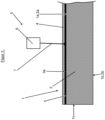
- Im Folgenden wird die Erfindung anhand einer Zeichnung beispielhaft näher erläutert. Es zeigen:
- Figur 1:
- Stark vereinfacht und schematisch einen Schnitt durch eine Glastafel mit Schutzschicht mit einer Markierungseinrichtung für das erfindungsgemäße Markierungsverfahren
- Figur 2:
- Stark vereinfacht und schematisch einen Schnitt durch eine Glastafel mit einer darunter angeordneten Markierungseinrichtung für das nicht erfindungsgemäße Markierungsverfahren
- Eine erfindungsgemäß zu markierende Glastafel 1 (
Fig. 1 ,2 ) weist eine erste und zweite Glasoberfläche 1a;b sowie vorzugsweise eine umlaufende Glastafelkante 1c auf. Die Glastafel 1 weist vorzugsweise nur eine einzelne bzw. einzige Glasscheibe 2 (Fig. 1 ) auf. Jede Glasscheibe 2 weist zwei Glasscheibenoberflächen 2a;b auf. Weist die Glastafel 1 nur eine einzige Glasscheibe 2 auf, bilden die beiden Glasscheibenoberflächen 2a;b die Glasoberflächen 1a;b der Glastafel 1a;b. Besonders bevorzugt handelt es sich bei der Glastafel 1 um eine ESG-Glastafel mit einer einzigen noch vorzuspannenden bzw. bereits vorgespannten Glasscheibe 2. - Es kann sich bei der Glastafel 1 aber auch um eine Verbundglastafel aus mehreren miteinander verbundenen Glasscheiben 2 handeln (nicht dargestellt). Bei Verbundglastafeln handelt es sich um ein Laminat aus mindestens zwei einzelnen Glasscheiben 2, die jeweils mittels einer klebfähigen Zwischenschicht aus Kunststoff, insbesondere durch eine hochreißfeste, zähelastische, thermoplastische Folie, miteinander verbunden sind. In diesem Fall bilden jeweils die beiden außenliegenden Glasscheibenoberflächen 2a;b die Glasoberflächen 1a;b der Glastafel 1a;b. Bei den Glasscheiben 2 der Verbundglastafel handelt es sich vorzugsweise zumindest teilweise um vorgespannte Glasscheiben 2.
- Zudem weist die Glastafel 1 an zumindest einer ihrer beiden Glasoberflächen 1a;b eine oberflächliche Funktionsbeschichtung 3 auf. Die Funktionsbeschichtung 3 weist eine der oder den Glasscheiben 2 abgewandte, äußere Funktionsbeschichtungsoberfläche 3a auf.
- Die Funktionsbeschichtung 3 kann eine oder mehrere einzelne Funktionsschichten aufweisen. Bei mehreren Funktionsschichten handelt es sich somit um ein Funktionsschichtenlaminat. Die Funktionsschichten ändern bestimmte Eigenschaften der Glastafel 1 bzw. verleihen dieser bestimmte Funktionen. Die Funktionen können dabei z.B. Wärmeschutz, Sonnenschutz, oder Beheizung sein. Bevorzugt handelt es sich bei der Funktionsbeschichtung 3 um eine Wellenlängenselektive bzw. Low-E-Beschichtung. Die Funktionsbeschichtung 3 wird vor dem bestimmungsgemäßen Gebrauch der Glastafel 1 nicht entfernt, sondern ist auch beim bestimmungsgemäßen Gebrauch der Glastafel 1 noch vorhanden.
- Die Funktionsbeschichtung 3 der Glastafel 1 weist zumindest eine metallhaltige Funktionsschicht auf. Vorzugsweise handelt es sich jeweils um eine Metall- oder eine, bevorzugt keramische, Metalloxidschicht. Die metallischen Funktionsschichten sind vorzugsweise in oxidische Funktionsschichten, z.B. aus einem Metalloxid, vorzugsweise aus Zinnoxid, eingebettet, wodurch sich Transmission und Haltbarkeit erhöhen.
- Außerdem kann die Funktionsbeschichtung 3 eine Funktionsschicht aus, bevorzugt keramischem, Metalloxid, vorzugsweise aus Zinnoxid, aufweisen, die direkt mit der Glasoberfläche 1a;b verbunden ist, und die übrigen Schichten der Funktionsbeschichtung 3 mit der Glasoberfläche 1a;b verbindet. Die Funktionsschicht aus Metalloxid, vorzugsweise Zinnoxid, dient somit zugleich als Haftschicht.
- Vorzugsweise weist eine metallhaltige, bevorzugt eine metallische Funktionsschicht Silber, Kupfer oder Gold auf. Eine Funktionsschicht aus Metalloxid besteht vorzugsweise aus Zinnoxid.
- Selbstverständlich muss die keramische Funktionsschicht nicht aus Oxidkeramik bestehen. Es kann sich z.B. auch um eine nichtoxidische keramische Funktionsschicht handeln.
- Die Funktionsbeschichtung 3 der Glastafel 1 weist somit zumindest eine metallische und/oder zumindest eine, bevorzugt metallhaltige, keramische Funktionsschicht auf.
- Das Aufbringen der Funktionsschichten auf die Glasscheibe 2 erfolgt vorzugsweise durch Sputtern oder nasschemisch.
- Des Weiteren weist die Funktionsbeschichtung 3 vorzugsweise eine Dicke von < 2 µm, bevorzugt < 1 µm, auf.
- Zudem weist die Glastafel 1 an zumindest einer ihrer beiden Glasoberflächen 1a;b eine Schutzbeschichtung 4 in Form einer Polymerschutzschicht oder einer abziehbaren Schutzfolie auf. Die Schutzbeschichtung 4 deckt die jeweilige Glasoberfläche 1a;b und die Funktionsbeschichtung 3 nach außen hin ab und schützt insbesondere die unter der Schutzbeschichtung 4 angeordnete Funktionsbeschichtung 3 oder, wenn keine Funktionsbeschichtung 3 vorhanden ist, die reine Glasoberfläche 1a;b, vor mechanischer Beschädigung. Die Schutzbeschichtung 4 bildet somit die äußere bzw. außenliegende Schicht der Glastafel 1.
- Im Gegensatz zur Funktionsbeschichtung 3 wird die Schutzbeschichtung 4 vor der endgültigen Verwendung der Glastafel 1 vollständig entfernt. Sie ist somit nicht dauerhaft vorhanden. Die Schutzfolie wird abgezogen und die Polymerschutzschicht wird verbrannt. Die Funktionsbeschichtung 3 dagegen ist zumindest bereichsweise dauerhaft vorhanden.
- Die Polymerschutzschicht besteht aus einem Polymer und ist nicht von der Glastafel 1 abziehbar. Die Polymerschutzschicht ist mit der jeweiligen Oberfläche (Funktionsbeschichtungsoberfläche 3a oder Glasoberfläche 1a;b) fest bzw. unlösbar bzw. nicht zerstörungsfrei verbunden.
- Zudem weist die Polymerschutzschicht vorzugsweise eine Dicke von 1 µm bis 1 mm, bevorzugt 1 µm bis 100 µm, auf.
- Die Schutzfolie besteht aus Kunststoff, vorzugsweise Polyvinylchlorid (PVC), und ist von der Glastafel 1 abziehbar.
- Zudem weist die Schutzfolie vorzugsweise eine Dicke von 20 bis 100 µm auf.
- Wie bereits erläutert wird nicht erfindungsgemäß durch Aufdrucken von Markierungsmaterial mittels Laserstrahlung oder erfindungsgemäß durch farbliche Veränderung der Funktionsbeschichtung 3 eine Markierung auf der Glastafel 1 erzeugt, wobei gleichzeitig die Schutzbeschichtung 4 im Bereich der Markierung mittels der Laserstrahlung abgetragen, vorzugsweise verbrannt wird.
-
Fig. 2 zeigt eine beispielhaft eine Markierungsvorrichtung 5 zur Durchführung des nicht erfindungsgemäßen Markierungsverfahrens. -
Fig. 1 zeigt eine beispielhaft eine Markierungsvorrichtung 5 zur Durchführung des erfindungsgemäßen Markierungsverfahrens. - Die Markierungsvorrichtung 5 weist eine Laserstrahlerzeugungseinrichtung 6 zur Erzeugung eines Laserstrahls 7 auf. Zur Durchführung des nicht erfindungsgemäßen Verfahrens weist die Markierungsvorrichtung 5 zudem ein Spender- bzw. Trägermedium 8, mehrere Führungsrollen 9 und einen Andruckrahmen 10 auf.
- Die Laserstrahlerzeugungseinrichtung 6 dient zum Abtragen der Polymerschutzschicht bzw. der Schutzfolie im Bereich der zu erzeugenden Markierung und zur Erzeugung der Markierung im gleichen Arbeitsgang. Dazu erzeugt die Laserstrahlerzeugungseinrichtung 6 den Laserstrahl 7. Die Laserstrahlerzeugungseinrichtung 6 weist dazu eine Laserstrahlungsquelle und eine dazugehörige Optik auf. Mittels der Optik wird der Laserstrahl 7 fokussiert. Dabei kann der Laserstrahl 7 von einer Ausgangsposition, in der er vertikal bzw. senkrecht zur Glasoberfläche 1a;b ausgerichtet ist, verschwenkt bzw. ausgelenkt werden.
- Die Laserstrahlungsquelle erzeugt dabei vorzugsweise einen Laserstrahl 7, dessen Wellenlänge bei 190 nm bis 12 µm, bevorzugt bei 500 nm bis 2 µm, liegt.
- Zudem erzeugt die Laserstrahlungsquelle vorzugsweise einen Laserstrahl 7, dessen Laserleistung bei < 20 W, bevorzugt < 10 W, und/oder bei ≥ 0,5 W, bevorzugt bei ≥ 5 W, liegt.
- Außerdem erzeugt die Laserstrahlungsquelle vorzugsweise einen gepulsten Laserstrahl 7. Sie kann aber auch einen kontinuierlichen Laserstrahl 7 erzeugen.
- Bei dem Spender- bzw. Trägermedium 8 handelt es sich vorzugsweise um eine beschichtete Kunststofffolie, bevorzugt aus PET. Dabei ist das Trägermedium 8 vorzugsweise bandförmig.
- Des Weiteren weist das Trägermedium 8 eine oberflächliche Markierungsbeschichtung aus Markierungsmaterial auf, welche zumindest eine metallhaltige, vorzugsweise metallische, Markierungsschicht und/oder zumindest eine keramische Markierungsschicht aufweist.
- Vorzugsweise handelt es sich bei der metallhaltigen Markierungsschicht jeweils um eine Metall- oder eine, bevorzugt keramische, Metalloxidschicht. Die metallischen Markierungsschichten sind vorzugsweise in oxidische Funktionsschichten, z.B. aus einem Metalloxid, vorzugsweise aus Zinnoxid, eingebettet.
- Außerdem kann die Markierungsbeschichtung eine Markierungsschicht aus, bevorzugt keramischem, Metalloxid, vorzugsweise aus Zinnoxid, aufweisen, die direkt mit der Oberfläche des Trägermediums 8 verbunden ist, und die übrigen Schichten der Markierungsbeschichtung mit der Oberfläche verbindet. Die Markierungsschicht aus Metalloxid, vorzugsweise Zinnoxid, dient somit zugleich als Haftschicht.
- Vorzugsweise weist eine metallhaltige, bevorzugt eine metallische Markierungsschicht Silber, Kupfer oder Gold auf.
- Selbstverständlich muss die keramische Markierungsschicht nicht aus Oxidkeramik bestehen. Es kann sich z.B. auch um eine nichtoxidische keramische Markierungsschicht handeln.
- Die Markierungsbeschichtung der Glastafel 1 weist somit zumindest eine metallische und/oder zumindest eine, bevorzugt metallhaltige, keramische Markierungsschicht auf.
- Das Aufbringen der Markierungsschichten auf das Trägermedium 8 erfolgt vorzugsweise durch Sputtern oder nasschemisch.
- Bei der Markierungsbeschichtung handelt es sich zweckmäßigerweise um eine Low-E-Beschichtung.
- Des Weiteren weist die Markierungsbeschichtung vorzugsweise eine Dicke von < 5 µm auf.
- Der Andruckrahmen 10 dient zum Andrücken des bandförmigen Trägermediums 8 an die zu markierende Glastafel 1. Dabei ist der Andruckrahmen 10 vorzugsweise durchlässig für die Laserstrahlung. Alternativ dazu weist der Andruckrahmen 10 eine Öffnung auf, die den Markierungsbereich freigibt.
- Das bandförmige Trägermedium 8 ist zudem um die Führungsrollen 9 herum geführt.
- Zur Markierung wird nun das Trägermedium 8 mit seiner mit der Markierungsbeschichtung beschichteten Seite mittels des Andruckrahmens 10 an die Glastafel 1 angedrückt. Dann wird mittels des auf die Markierungsbeschichtung fokussierten Laserstrahls 7 Markierungsmaterial aus der Markierungsbeschichtung auf die Glastafel 1, insbesondere die Funktionsbeschichtungsoberfläche 3a und/oder die Glasoberfläche 1a;b übertragen und an dieser fixiert. Dadurch, dass die Laserstrahlung von dem Markierungsmaterial absorbiert wird, wird dieses von dem Trägermedium 8 gelöst und auf die zu markierende Oberfläche 1a;b;3a befördert.
- Gleichzeitig bzw. in demselben Arbeitsgang wird dabei die Schutzbeschichtung 4 mittels des Laserstrahls 7 abgetragen, insbesondere verbrannt, um die zu markierende Oberfläche 1a;b;3a frei zu legen.
- Sowohl das Material des Andruckrahmens 10 als auch des Trägermediums 8 sind dabei bei der Laserwellenlänge des Laserstrahls 7 höchstens schwach absorbierend, so dass der Laserstrahl 7 durch Trägermedium 8 und den Andruckrahmen 10 hindurch geht.
- Zum Markieren müssen die Glastafel 1 und der Laserstrahl 7 und gegebenenfalls das Trägermedium 8 relativ zueinander parallel zu den Glasoberflächen 1a;b bewegt werden. Vorzugsweise wird nur der Laserstrahl 7 bewegt. Die Bewegung des Laserstrahls 7 erfolgt dabei vorzugsweise mittels der Optik der Laserstrahlerzeugungseinrichtung 6. Die Optik der Lasererzeugungseinrichtung 6 ist nämlich vorzugsweise in der Lage, mit Hilfe von zwei verstellbaren Spiegeln (Scanoptik) den Laserstrahl 7 in einem Bereich von z.B. 100 mm x 100 mm (Scanfeld) zu bewegen. Nach der Markierung wird dann das bandförmige Trägermedium 8 nach vorne gerückt.
- Das Markieren erfolgt somit durch Einbringen von Brennspuren bzw. Laserspuren in die Schutzbeschichtung 4 und Übertragen von Markierungsmaterial aus der Markierungsbeschichtung vom Trägermedium 8 auf die Glastafel 1, insbesondere auf die Funktionsbeschichtungsoberfläche 3a und/oder die Glasoberfläche 1a;b. Die Laserspuren können punktförmig, linienförmig oder flächig sein. Im Bereich der Laserspuren ist die Schutzbeschichtung 4 vollständig abgetragen, insbesondere verdampft bzw. verbrannt, und das Markierungsmaterial ist auf die dadurch frei gewordene bzw. frei gelegte Oberfläche 1a;b,3a aufgetragen.
- Wie bereits erläutert, erfolgt das Markieren beim erfindungsgemäßen Verfahren durch Einbringen von Brennspuren bzw. Laserspuren in die Schutzbeschichtung 4 und die Funktionsbeschichtung 3. Im Bereich der Laserspuren ist die Schutzbeschichtung 4 vollständig abgetragen, insbesondere verdampft bzw. verbrannt, und die Funktionsbeschichtung 3 ist verfärbt.
- Ursache für die Entstehung der Verfärbungen ist unter anderem die Absorption der Laserstrahlung in der metallischen oder keramischen Funktionsschicht. Diese wird durch die Absorption so stark erwärmt, dass es im bestrahlten Bereich zu einer Veränderung des Materials der Funktionsbeschichtung kommt. Als Folge der Veränderung liegt beispielsweise das Metall in Form von Nanopartikeln vor, eingebettet in eine Matrix, gebildet zumindest teilweise aus Material aus den anderen ursprünglich in der Funktionsbeschichtung 3 vorhandenen Funktionsschichten. Oder die chemische Struktur des Materials wird so geändert, dass es sich verfärbt.
- Diese Mechanismen bzw. daraus resultierenden Verfärbungen treten in der Regel auch bei dem Markierungsmaterial der Markierungsbeschichtung des Trägermediums auf.
- Vorteil des erfindungsgemäßen Verfahrens ist, dass auch ESG-Glastafeln mit einer Schutzbeschichtung 4 dauerhaft markiert werden können. Die noch nicht vorgespannten Glastafeln 1 können markiert werden und die Markierung bleibt trotz Wegbrennens der Polymerbeschichtung bei der Wärmebehandlung erhalten. Dadurch können auch Prüfmarkierungen angebracht werden, welche durch einen Farbumschlag anzeigen, dass die notwendige Zeit für die Temperaturbehandlung erreicht ist.
- Zudem können auch bereits vorgespannte ESG-Glastafeln mit Schutzfolie markiert werden.
- Die erfindungsgemäß erzeugten Markierungen sind hochgradig beständig gegen Abrieb und Witterungseinflüsse sowie Temperaturen, Lösungsmittel oder sonstige Chemikalien. Es wird somit eine optimale Markierung über die gesamte Lebensdauer der Glastafel 1 gewährleistet.
- Die Markierungsvorrichtung 5 zur Durchführung des erfindungsgemäßen Verfahrens kann problemlos in Schneid- und Brechlinien integriert werden oder als Einzelplatzsystem ausgebildet werden. Beispielsweise kann die Markierungsvorrichtung in die Schneidbrücke integriert werden.
- Zudem kann mit dem erfindungsgemäßen Verfahren eine vollautomatische Kennzeichnung mit maschinenlesbaren Codes (z.B. Data-Matrix-Codes), Logos und Produkt-IDs, Seriennummern, auftragsspezifischen Daten individuell für jede Glastafel durchgeführt werden.
- Dabei war nicht ohne weiteres vorhersehbar, das die Aufbringung einer Markierung auf eine unterhalb der Schutzbeschichtung 4 liegende Oberfläche 1a;b;3a möglich ist. Die Laserstrahlung wird von der Markierungsbeschichtung, insbesondere von der oder den Markierungsschichten, absorbiert. Dadurch wird die Markierungsbeschichtung, insbesondere wird bzw. werden die Markierungsschicht(en), zumindest teilweise bzw. teilmengenweise von dem Trägermedium 8 abgesprengt. Es wird nun davon ausgegangen, dass die dabei frei werdende Energie überraschenderweise dazu führt, dass die Schutzbeschichtung 4 abgetragen wird und so die zu markierende Oberfläche frei gelegt wird. Es werden offenbar Temperaturen erreicht, die ähnlich dem Ofenprozess zur Verbrennung der Schutzbeschichtung führen. Das Markierungsmaterial bzw. das Material der Funktionsschichten kann hingegen nicht verbrennen, da es ein Metall oder eine Keramik ist.
- Des Weiteren kann der Laserstrahl 7 auch durch die Glastafel 1 durch auf die Markierungsbeschichtung bzw. die Funktionsbeschichtung 3 gerichtet werden. Dies erleichtert die Integration der Laserkennzeichnung in den Arbeitsablauf bei der Ofenbeschickung.
- Es wurde ein 1 µm-Laser auf die beschichtete Glasoberfläche einer mit einer Polymerschutzschicht versehenen ESG-Glastafel gerichtet. Die ESG-Glastafel wies zudem eine Low-E-Beschichtung mit einer Silberschicht auf. Die Laserleistung betrug 5 W. Die Frequenz des gepulsten Laserstrahls betrug 10 kHz. Der Strahldurchmesser im Fokus lag bei 100 µm.
- Es wurde eine dauerhafte Markierung in der Low-E-Beschichtung erzeugt und die Polymerschutzschicht im Bereich der Markierung entfernt.
Claims (10)
- Markierungsverfahren zur Markierung von Glastafeln (1), die zumindest an einer ihrer beiden Glasoberflächen (1a;b) eine Schutzbeschichtung (4) in Form einer Polymerbeschichtung oder in Form einer abziehbaren Schutzfolie aus Kunststoff, und eine unter der Schutzbeschichtung (4) angeordnete Funktionsbeschichtung (3) mit mindestens einer metallhaltigen und/oder mindestens einer keramischen Funktionsschicht aufweisen,
dadurch gekennzeichnet, dass
die Schutzbeschichtung (4) im Bereich einer aufzubringenden Markierung mittels Laserstrahlung abgetragen, insbesondere verbrannt, wird, und im gleichen Arbeitsgang mittels der Laserstrahlung die Funktionsbeschichtung (3) zur Erzeugung der Markierung im durch das Abtragen der Schutzbeschichtung (4) frei gelegten Bereich farblich verändert wird. - Markierungsverfahren nach Anspruch 1,
dadurch gekennzeichnet, dassa) die Laserstrahlung von der Funktionsbeschichtung (3) derart absorbiert wird, dass das Material der Funktionsbeschichtung (3) verfärbt wird,
und/oderb) durch die bei der Absorption frei werdende Energie die Schutzbeschichtung (4) abgetragen wird. - Markierungsverfahren nach Anspruch 1 oder 2,
dadurch gekennzeichnet, dass
ein Laserstrahl (7)a) mit einer Wellenlänge von 190 nm bis 12 µm, bevorzugt von 500 nm bis 2 µm,
und/oderb) mit einer Laserleistung < 20 W, bevorzugt mit einer Laserleistung < 10 W,
und/oderc) mit einer Laserleistung von ≥ 0,5 W, bevorzugt mit einer Laserleistung von ≥ 5 W,verwendet wird. - Markierungsverfahren nach einem der vorhergehenden Ansprüche,
dadurch gekennzeichnet, dass
ein gepulster Laserstrahl (7) oder ein kontinuierlicher Laserstrahl (7) verwendet wird. - Markierungsverfahren nach einem der vorhergehenden Ansprüche,
dadurch gekennzeichnet, dass
noch nicht vorgespannte Einscheiben-Sicherheitsglastafeln markiert werden. - Markierungsverfahren nach einem der vorhergehenden Ansprüche,
dadurch gekennzeichnet, dassa) die Funktionsschicht eine Metallschicht oder eine, bevorzugt keramische, Metalloxidschicht ist,
und/oderb) es sich bei der Funktionsbeschichtung (3) um eine Low-E-Beschichtung handelt. - Markierungsverfahren nach einem der vorhergehenden Ansprüche,
dadurch gekennzeichnet, dass
die Polymerschutzschicht aus einem Polymer besteht und nicht von der Glastafel (1) abziehbar ist und/oder dass die Polymerschutzschicht eine Dicke von 1 µm bis 1 mm, bevorzugt 1 µm bis 100 µm, aufweist. - Markierungsverfahren nach einem der vorhergehenden Ansprüche,
dadurch gekennzeichnet, dass
die Schutzfolie aus Kunststoff, vorzugsweise Polyvinylchlorid (PVC), besteht und von der Glastafel (1) abziehbar ist und/oder dass die Schutzfolie eine Dicke von 20 bis 100 µm aufweist. - Markierungsverfahren nach einem der vorhergehenden Ansprüche,
dadurch gekennzeichnet, dass
die Laserstrahlung durch die Glastafel (1) durch oder nicht durch die Glastafel (1) durch gestrahlt wird. - Markierungsverfahren nach einem der vorhergehenden Ansprüche,
dadurch gekennzeichnet, dassein fokussierter Laserstrahl (7) verwendet wird,wobei der Laserstrahl (7) vorzugsweise auf die beschichtete Glasoberfläche (1a) fokussiert wird.
Applications Claiming Priority (3)
| Application Number | Priority Date | Filing Date | Title |
|---|---|---|---|
| DE102018207181.0A DE102018207181B4 (de) | 2018-05-08 | 2018-05-08 | Verfahren zum Markieren von Glastafeln, vorzugsweise von Einscheiben-Sicherheitsglastafeln |
| EP19717260.4A EP3732054B1 (de) | 2018-05-08 | 2019-04-05 | Verfahren zum markieren von glastafeln, vorzugsweise von einscheiben-sicherheitsglastafeln |
| PCT/EP2019/058725 WO2019214884A1 (de) | 2018-05-08 | 2019-04-05 | Verfahren zum markieren von glastafeln, vorzugsweise von einscheiben-sicherheitsglastafeln |
Related Parent Applications (2)
| Application Number | Title | Priority Date | Filing Date |
|---|---|---|---|
| EP19717260.4A Division-Into EP3732054B1 (de) | 2018-05-08 | 2019-04-05 | Verfahren zum markieren von glastafeln, vorzugsweise von einscheiben-sicherheitsglastafeln |
| EP19717260.4A Division EP3732054B1 (de) | 2018-05-08 | 2019-04-05 | Verfahren zum markieren von glastafeln, vorzugsweise von einscheiben-sicherheitsglastafeln |
Publications (4)
| Publication Number | Publication Date |
|---|---|
| EP4242180A2 true EP4242180A2 (de) | 2023-09-13 |
| EP4242180A3 EP4242180A3 (de) | 2023-12-06 |
| EP4242180B1 EP4242180B1 (de) | 2024-12-18 |
| EP4242180C0 EP4242180C0 (de) | 2024-12-18 |
Family
ID=66165937
Family Applications (2)
| Application Number | Title | Priority Date | Filing Date |
|---|---|---|---|
| EP19717260.4A Active EP3732054B1 (de) | 2018-05-08 | 2019-04-05 | Verfahren zum markieren von glastafeln, vorzugsweise von einscheiben-sicherheitsglastafeln |
| EP23187829.9A Active EP4242180B1 (de) | 2018-05-08 | 2019-04-05 | Verfahren zum markieren von glastafeln, vorzugsweise von einscheiben-sicherheitsglastafeln |
Family Applications Before (1)
| Application Number | Title | Priority Date | Filing Date |
|---|---|---|---|
| EP19717260.4A Active EP3732054B1 (de) | 2018-05-08 | 2019-04-05 | Verfahren zum markieren von glastafeln, vorzugsweise von einscheiben-sicherheitsglastafeln |
Country Status (6)
| Country | Link |
|---|---|
| US (1) | US12448326B2 (de) |
| EP (2) | EP3732054B1 (de) |
| CA (1) | CA3099015C (de) |
| DE (1) | DE102018207181B4 (de) |
| MX (1) | MX2020010260A (de) |
| WO (1) | WO2019214884A1 (de) |
Families Citing this family (4)
| Publication number | Priority date | Publication date | Assignee | Title |
|---|---|---|---|---|
| DE102018217970A1 (de) | 2018-10-19 | 2020-04-23 | Hegla Boraident Gmbh & Co. Kg | Verfahren zur Herstellung einer elektronischen Struktur auf einer Glasscheibe sowie Glastafel mit mindestens einer derartigen Glasscheibe |
| DE102021213645A1 (de) | 2021-12-01 | 2023-06-01 | Hegla Boraident Gmbh & Co. Kg | Einzäunung, vorzugsweise für Tiergehege sowie Verwendung einer Glastafel dafür und Verwendung von Laservorrichtungen |
| DE102021215023B3 (de) | 2021-12-23 | 2023-05-11 | Hegla Boraident Gmbh & Co. Kg | Mobile Laservorrichtung und deren Verwendung sowie Verfahren zur Bearbeitung einer Glastafel |
| DE102023205505B3 (de) * | 2023-06-13 | 2024-09-05 | Hegla Boraident Gmbh & Co. Kg | Lasertransferdruckvorrichtung und deren Verwendung sowie Verfahren zum Beschichten einer Glastafel mittels Lasertransferdruck |
Citations (5)
| Publication number | Priority date | Publication date | Assignee | Title |
|---|---|---|---|---|
| US20030039765A1 (en) | 1997-03-21 | 2003-02-27 | Hirotoshi Hayakawa | Marking method and marking material |
| DE10258522A1 (de) | 2002-12-14 | 2004-07-01 | Volkswagen Ag | Verfahren zum Markieren einer Verbundglasscheibe und Verbundglasscheibe mit Markierung |
| DE102005025982A1 (de) | 2005-06-03 | 2006-12-07 | Martin-Luther-Universität Halle-Wittenberg | Low-E-Schichsysteme mit farbigen Strukturen und Verfahren zur Erzeugung der Strukturen |
| DE102005026038A1 (de) | 2005-06-03 | 2006-12-07 | Boraglas Gmbh | Verfahren zur Markierung von Objektoberflächen |
| EP3031785A1 (de) | 2014-12-12 | 2016-06-15 | Schott AG | Verfahren zur herstellung eines glaskeramikelements mit strukturierter beschichtung |
Family Cites Families (2)
| Publication number | Priority date | Publication date | Assignee | Title |
|---|---|---|---|---|
| DE10351226A1 (de) | 2003-10-27 | 2005-06-09 | Baublys Control Laser Gmbh | Verfahren zum Beschriften von Glas mittels Laser |
| TW202224211A (zh) * | 2016-03-31 | 2022-06-16 | 美商伊雷克托科學工業股份有限公司 | 用於導電電鍍的雷射種晶之方法 |
-
2018
- 2018-05-08 DE DE102018207181.0A patent/DE102018207181B4/de active Active
-
2019
- 2019-04-05 US US17/044,542 patent/US12448326B2/en active Active
- 2019-04-05 WO PCT/EP2019/058725 patent/WO2019214884A1/de not_active Ceased
- 2019-04-05 EP EP19717260.4A patent/EP3732054B1/de active Active
- 2019-04-05 EP EP23187829.9A patent/EP4242180B1/de active Active
- 2019-04-05 CA CA3099015A patent/CA3099015C/en active Active
- 2019-04-05 MX MX2020010260A patent/MX2020010260A/es unknown
Patent Citations (5)
| Publication number | Priority date | Publication date | Assignee | Title |
|---|---|---|---|---|
| US20030039765A1 (en) | 1997-03-21 | 2003-02-27 | Hirotoshi Hayakawa | Marking method and marking material |
| DE10258522A1 (de) | 2002-12-14 | 2004-07-01 | Volkswagen Ag | Verfahren zum Markieren einer Verbundglasscheibe und Verbundglasscheibe mit Markierung |
| DE102005025982A1 (de) | 2005-06-03 | 2006-12-07 | Martin-Luther-Universität Halle-Wittenberg | Low-E-Schichsysteme mit farbigen Strukturen und Verfahren zur Erzeugung der Strukturen |
| DE102005026038A1 (de) | 2005-06-03 | 2006-12-07 | Boraglas Gmbh | Verfahren zur Markierung von Objektoberflächen |
| EP3031785A1 (de) | 2014-12-12 | 2016-06-15 | Schott AG | Verfahren zur herstellung eines glaskeramikelements mit strukturierter beschichtung |
Also Published As
| Publication number | Publication date |
|---|---|
| DE102018207181B4 (de) | 2023-06-29 |
| EP3732054B1 (de) | 2023-08-30 |
| US12448326B2 (en) | 2025-10-21 |
| MX2020010260A (es) | 2020-10-22 |
| CA3099015C (en) | 2023-04-04 |
| EP4242180A3 (de) | 2023-12-06 |
| EP4242180B1 (de) | 2024-12-18 |
| EP4242180C0 (de) | 2024-12-18 |
| WO2019214884A1 (de) | 2019-11-14 |
| CA3099015A1 (en) | 2019-11-14 |
| DE102018207181A1 (de) | 2019-11-14 |
| EP3732054A1 (de) | 2020-11-04 |
| US20210107828A1 (en) | 2021-04-15 |
| EP3732054C0 (de) | 2023-08-30 |
Similar Documents
| Publication | Publication Date | Title |
|---|---|---|
| EP4242180B1 (de) | Verfahren zum markieren von glastafeln, vorzugsweise von einscheiben-sicherheitsglastafeln | |
| DE102009036164B4 (de) | Verfahren zum Biegen und thermischen Vorspannen von Strahlenschutzglas | |
| EP3390044B1 (de) | Beheizbares verbundglas mit dünner innenscheibe und dünner aussenscheibe | |
| EP1885555B1 (de) | Farbig strukturierte low-e-schichtsysteme und verfahren zur erzeugung der farbig strukturierten low-e-schichtsysteme sowie deren verwendung | |
| EP2322353A1 (de) | Verfahren zum Aufbringen einer dauerhaften Prozessmarke auf einem Produkt, insbesondere Glas | |
| EP1728770B1 (de) | Verfahren zur Markierung von Objektoberflächen | |
| EP3720825B1 (de) | Verfahren zur herstellung einer bedruckten beschichteten scheibe | |
| EP4347254A1 (de) | Verglasung mit metallbasierter beschichtung und schutzschicht am rand | |
| EP3717430B1 (de) | Verfahren zur herstellung einer bedruckten beschichteten scheibe | |
| DE102018217970A1 (de) | Verfahren zur Herstellung einer elektronischen Struktur auf einer Glasscheibe sowie Glastafel mit mindestens einer derartigen Glasscheibe | |
| EP4255861B1 (de) | Verfahren zum löschen einer laserinduzierten markierung von glastafeln sowie verfahren und vorrichtungen zum markieren und entmarkieren von glastafeln, vorzugsweise von basisglastafeln, bevorzugt von floatglastafeln | |
| EP4007745B1 (de) | Entschichtungseinrichtung und -verfahren zum entschichten von glasscheiben, sowie verfahren zur herstellung von glasscheiben für stufenglas, stufenglas und stufenglasfenster und verwendung der glasscheibe für eine isolierverglasung, insbesondere für ein stufenglas eines stufenglasfensters | |
| EP1379477A1 (de) | Verfahren zur herstellung farbiger strukturen eines glases | |
| EP3206999B1 (de) | Verfahren zur herstellung eines fassadenelementes aus glas zur abschirmung von licht und lichtabschirmendes fassadenelement | |
| DE10258522B4 (de) | Verfahren zum Markieren einer Verbundglasscheibe und Verbundglasscheibe mit Markierung | |
| WO2016055166A2 (de) | Beschichtungsfolie, schichtaufbau, sowie verfahren zum beschichten eines substrats | |
| DE202021004211U1 (de) | Gebogene Scheibe mit Funktionsschicht | |
| DE102020215235A1 (de) | Verfahren zum Erzeugen von farbigen, 3-dimensionalen Strukturen in Glaselementen | |
| DE202025100388U1 (de) | Fahrzeugdachverbundscheibe mit Wärmestrahlen reflektierender innenseitiger Beschichtung und großflächigem Kommunikationsfenster | |
| WO2021254766A1 (de) | Verfahren zur herstellung einer gebogenen, beschichteten fahrzeugscheibe mit einer opaken abdeckbeschichtung und einer transparenten beschichtung | |
| WO2023161080A1 (de) | Verfahren zur herstellung eines mit einer diamantähnlichen beschichtung versehenen wärmebehandelten substrats | |
| DE102018118964A1 (de) | Verfahren zur Herstellung von zumindest einer teilflächigen keramischen Bedruckung auf einem mit einer vorspannbaren Funktionsbeschichtung versehenen Floatglasssubstrat | |
| DE102006027263A1 (de) | Substrat mit Schichtabfolge zur Erzeugung eines in Abhängigkeit des Blickwinkels sich ändernden Farbeindrucks |
Legal Events
| Date | Code | Title | Description |
|---|---|---|---|
| PUAI | Public reference made under article 153(3) epc to a published international application that has entered the european phase |
Free format text: ORIGINAL CODE: 0009012 |
|
| STAA | Information on the status of an ep patent application or granted ep patent |
Free format text: STATUS: THE APPLICATION HAS BEEN PUBLISHED |
|
| AC | Divisional application: reference to earlier application |
Ref document number: 3732054 Country of ref document: EP Kind code of ref document: P |
|
| AK | Designated contracting states |
Kind code of ref document: A2 Designated state(s): AL AT BE BG CH CY CZ DE DK EE ES FI FR GB GR HR HU IE IS IT LI LT LU LV MC MK MT NL NO PL PT RO RS SE SI SK SM TR |
|
| REG | Reference to a national code |
Ref legal event code: R079 Ref country code: DE Ref legal event code: R079 Ref document number: 502019012675 Country of ref document: DE Free format text: PREVIOUS MAIN CLASS: C03C0017380000 Ipc: B41M0005260000 |
|
| PUAL | Search report despatched |
Free format text: ORIGINAL CODE: 0009013 |
|
| AK | Designated contracting states |
Kind code of ref document: A3 Designated state(s): AL AT BE BG CH CY CZ DE DK EE ES FI FR GB GR HR HU IE IS IT LI LT LU LV MC MK MT NL NO PL PT RO RS SE SI SK SM TR |
|
| RIC1 | Information provided on ipc code assigned before grant |
Ipc: B41M 5/24 20060101ALN20231027BHEP Ipc: C23C 14/28 20060101ALN20231027BHEP Ipc: C03C 23/00 20060101ALN20231027BHEP Ipc: C03C 17/38 20060101ALI20231027BHEP Ipc: C03C 17/36 20060101ALI20231027BHEP Ipc: C03C 17/34 20060101ALI20231027BHEP Ipc: C03C 17/32 20060101ALI20231027BHEP Ipc: B41M 5/26 20060101AFI20231027BHEP |
|
| STAA | Information on the status of an ep patent application or granted ep patent |
Free format text: STATUS: REQUEST FOR EXAMINATION WAS MADE |
|
| 17P | Request for examination filed |
Effective date: 20240208 |
|
| GRAP | Despatch of communication of intention to grant a patent |
Free format text: ORIGINAL CODE: EPIDOSNIGR1 |
|
| STAA | Information on the status of an ep patent application or granted ep patent |
Free format text: STATUS: GRANT OF PATENT IS INTENDED |
|
| GRAS | Grant fee paid |
Free format text: ORIGINAL CODE: EPIDOSNIGR3 |
|
| RIC1 | Information provided on ipc code assigned before grant |
Ipc: B41M 5/24 20060101ALN20241004BHEP Ipc: C23C 14/28 20060101ALN20241004BHEP Ipc: C03C 23/00 20060101ALN20241004BHEP Ipc: C03C 17/38 20060101ALI20241004BHEP Ipc: C03C 17/36 20060101ALI20241004BHEP Ipc: C03C 17/34 20060101ALI20241004BHEP Ipc: C03C 17/32 20060101ALI20241004BHEP Ipc: B41M 5/26 20060101AFI20241004BHEP |
|
| GRAA | (expected) grant |
Free format text: ORIGINAL CODE: 0009210 |
|
| STAA | Information on the status of an ep patent application or granted ep patent |
Free format text: STATUS: THE PATENT HAS BEEN GRANTED |
|
| INTG | Intention to grant announced |
Effective date: 20241018 |
|
| AC | Divisional application: reference to earlier application |
Ref document number: 3732054 Country of ref document: EP Kind code of ref document: P |
|
| AK | Designated contracting states |
Kind code of ref document: B1 Designated state(s): AL AT BE BG CH CY CZ DE DK EE ES FI FR GB GR HR HU IE IS IT LI LT LU LV MC MK MT NL NO PL PT RO RS SE SI SK SM TR |
|
| REG | Reference to a national code |
Ref country code: CH Ref legal event code: EP |
|
| REG | Reference to a national code |
Ref country code: DE Ref legal event code: R096 Ref document number: 502019012675 Country of ref document: DE |
|
| REG | Reference to a national code |
Ref country code: IE Ref legal event code: FG4D Free format text: LANGUAGE OF EP DOCUMENT: GERMAN |
|
| U01 | Request for unitary effect filed |
Effective date: 20241224 |
|
| U07 | Unitary effect registered |
Designated state(s): AT BE BG DE DK EE FI FR IT LT LU LV MT NL PT RO SE SI Effective date: 20250114 |
|
| PG25 | Lapsed in a contracting state [announced via postgrant information from national office to epo] |
Ref country code: HR Free format text: LAPSE BECAUSE OF FAILURE TO SUBMIT A TRANSLATION OF THE DESCRIPTION OR TO PAY THE FEE WITHIN THE PRESCRIBED TIME-LIMIT Effective date: 20241218 |
|
| PG25 | Lapsed in a contracting state [announced via postgrant information from national office to epo] |
Ref country code: NO Free format text: LAPSE BECAUSE OF FAILURE TO SUBMIT A TRANSLATION OF THE DESCRIPTION OR TO PAY THE FEE WITHIN THE PRESCRIBED TIME-LIMIT Effective date: 20250318 |
|
| PG25 | Lapsed in a contracting state [announced via postgrant information from national office to epo] |
Ref country code: GR Free format text: LAPSE BECAUSE OF FAILURE TO SUBMIT A TRANSLATION OF THE DESCRIPTION OR TO PAY THE FEE WITHIN THE PRESCRIBED TIME-LIMIT Effective date: 20250319 |
|
| PG25 | Lapsed in a contracting state [announced via postgrant information from national office to epo] |
Ref country code: RS Free format text: LAPSE BECAUSE OF FAILURE TO SUBMIT A TRANSLATION OF THE DESCRIPTION OR TO PAY THE FEE WITHIN THE PRESCRIBED TIME-LIMIT Effective date: 20250318 |
|
| U20 | Renewal fee for the european patent with unitary effect paid |
Year of fee payment: 7 Effective date: 20250423 |
|
| PG25 | Lapsed in a contracting state [announced via postgrant information from national office to epo] |
Ref country code: SM Free format text: LAPSE BECAUSE OF FAILURE TO SUBMIT A TRANSLATION OF THE DESCRIPTION OR TO PAY THE FEE WITHIN THE PRESCRIBED TIME-LIMIT Effective date: 20241218 |
|
| PG25 | Lapsed in a contracting state [announced via postgrant information from national office to epo] |
Ref country code: PL Free format text: LAPSE BECAUSE OF FAILURE TO SUBMIT A TRANSLATION OF THE DESCRIPTION OR TO PAY THE FEE WITHIN THE PRESCRIBED TIME-LIMIT Effective date: 20241218 |
|
| PG25 | Lapsed in a contracting state [announced via postgrant information from national office to epo] |
Ref country code: ES Free format text: LAPSE BECAUSE OF FAILURE TO SUBMIT A TRANSLATION OF THE DESCRIPTION OR TO PAY THE FEE WITHIN THE PRESCRIBED TIME-LIMIT Effective date: 20241218 |
|
| PG25 | Lapsed in a contracting state [announced via postgrant information from national office to epo] |
Ref country code: IS Free format text: LAPSE BECAUSE OF FAILURE TO SUBMIT A TRANSLATION OF THE DESCRIPTION OR TO PAY THE FEE WITHIN THE PRESCRIBED TIME-LIMIT Effective date: 20250418 |
|
| PG25 | Lapsed in a contracting state [announced via postgrant information from national office to epo] |
Ref country code: SK Free format text: LAPSE BECAUSE OF FAILURE TO SUBMIT A TRANSLATION OF THE DESCRIPTION OR TO PAY THE FEE WITHIN THE PRESCRIBED TIME-LIMIT Effective date: 20241218 |
|
| PG25 | Lapsed in a contracting state [announced via postgrant information from national office to epo] |
Ref country code: CZ Free format text: LAPSE BECAUSE OF FAILURE TO SUBMIT A TRANSLATION OF THE DESCRIPTION OR TO PAY THE FEE WITHIN THE PRESCRIBED TIME-LIMIT Effective date: 20241218 |
|
| PLBE | No opposition filed within time limit |
Free format text: ORIGINAL CODE: 0009261 |
|
| STAA | Information on the status of an ep patent application or granted ep patent |
Free format text: STATUS: NO OPPOSITION FILED WITHIN TIME LIMIT |
|
| REG | Reference to a national code |
Ref country code: CH Ref legal event code: L10 Free format text: ST27 STATUS EVENT CODE: U-0-0-L10-L00 (AS PROVIDED BY THE NATIONAL OFFICE) Effective date: 20251029 |
|
| REG | Reference to a national code |
Ref country code: CH Ref legal event code: H13 Free format text: ST27 STATUS EVENT CODE: U-0-0-H10-H13 (AS PROVIDED BY THE NATIONAL OFFICE) Effective date: 20251125 |
|
| 26N | No opposition filed |
Effective date: 20250919 |
|
| PG25 | Lapsed in a contracting state [announced via postgrant information from national office to epo] |
Ref country code: MC Free format text: LAPSE BECAUSE OF FAILURE TO SUBMIT A TRANSLATION OF THE DESCRIPTION OR TO PAY THE FEE WITHIN THE PRESCRIBED TIME-LIMIT Effective date: 20241218 |
|
| GBPC | Gb: european patent ceased through non-payment of renewal fee |
Effective date: 20250405 |
|
| PG25 | Lapsed in a contracting state [announced via postgrant information from national office to epo] |
Ref country code: GB Free format text: LAPSE BECAUSE OF NON-PAYMENT OF DUE FEES Effective date: 20250405 |
|
| PG25 | Lapsed in a contracting state [announced via postgrant information from national office to epo] |
Ref country code: CH Free format text: LAPSE BECAUSE OF NON-PAYMENT OF DUE FEES Effective date: 20250430 |
|
| PG25 | Lapsed in a contracting state [announced via postgrant information from national office to epo] |
Ref country code: IE Free format text: LAPSE BECAUSE OF NON-PAYMENT OF DUE FEES Effective date: 20250405 |
|
| U20 | Renewal fee for the european patent with unitary effect paid |
Year of fee payment: 8 Effective date: 20260324 |