EP4242599B1 - Dispositif de mesure et procédé de détermination d'une grandeur de mesure - Google Patents
Dispositif de mesure et procédé de détermination d'une grandeur de mesure Download PDFInfo
- Publication number
- EP4242599B1 EP4242599B1 EP23160055.2A EP23160055A EP4242599B1 EP 4242599 B1 EP4242599 B1 EP 4242599B1 EP 23160055 A EP23160055 A EP 23160055A EP 4242599 B1 EP4242599 B1 EP 4242599B1
- Authority
- EP
- European Patent Office
- Prior art keywords
- waveguide
- fluid
- measuring device
- measurement
- solid body
- Prior art date
- Legal status (The legal status is an assumption and is not a legal conclusion. Google has not performed a legal analysis and makes no representation as to the accuracy of the status listed.)
- Active
Links
Images


Classifications
-
- G—PHYSICS
- G01—MEASURING; TESTING
- G01N—INVESTIGATING OR ANALYSING MATERIALS BY DETERMINING THEIR CHEMICAL OR PHYSICAL PROPERTIES
- G01N29/00—Investigating or analysing materials by the use of ultrasonic, sonic or infrasonic waves; Visualisation of the interior of objects by transmitting ultrasonic or sonic waves through the object
- G01N29/04—Analysing solids
-
- G—PHYSICS
- G01—MEASURING; TESTING
- G01F—MEASURING VOLUME, VOLUME FLOW, MASS FLOW OR LIQUID LEVEL; METERING BY VOLUME
- G01F1/00—Measuring the volume flow or mass flow of fluid or fluent solid material wherein the fluid passes through a meter in a continuous flow
- G01F1/66—Measuring the volume flow or mass flow of fluid or fluent solid material wherein the fluid passes through a meter in a continuous flow by measuring frequency, phase shift or propagation time of electromagnetic or other waves, e.g. using ultrasonic flowmeters
- G01F1/662—Constructional details
-
- G—PHYSICS
- G01—MEASURING; TESTING
- G01F—MEASURING VOLUME, VOLUME FLOW, MASS FLOW OR LIQUID LEVEL; METERING BY VOLUME
- G01F1/00—Measuring the volume flow or mass flow of fluid or fluent solid material wherein the fluid passes through a meter in a continuous flow
- G01F1/66—Measuring the volume flow or mass flow of fluid or fluent solid material wherein the fluid passes through a meter in a continuous flow by measuring frequency, phase shift or propagation time of electromagnetic or other waves, e.g. using ultrasonic flowmeters
-
- G—PHYSICS
- G01—MEASURING; TESTING
- G01N—INVESTIGATING OR ANALYSING MATERIALS BY DETERMINING THEIR CHEMICAL OR PHYSICAL PROPERTIES
- G01N29/00—Investigating or analysing materials by the use of ultrasonic, sonic or infrasonic waves; Visualisation of the interior of objects by transmitting ultrasonic or sonic waves through the object
- G01N29/34—Generating the ultrasonic, sonic or infrasonic waves, e.g. electronic circuits specially adapted therefor
Definitions
- the invention relates to a measuring device for determining a measured variable, with a first and second ultrasonic transducer, a control device which is designed to control the first ultrasonic transducer in such a way that the first ultrasonic transducer excites a guided wave with a predetermined oscillation frequency f in a waveguide of the measuring device which is oscillation-coupled to the first ultrasonic transducer in such a way that the guided wave propagates in the waveguide parallel to a rear surface of the waveguide, wherein the control device is designed to determine the measured variable as a function of a received signal from the second ultrasonic transducer, wherein the received signal depends on oscillations of the second ultrasonic transducer caused directly and/or indirectly by the guided wave.
- the invention relates to a method for determining a measured variable.
- One way to measure a flow through a measuring tube is with an ultrasonic meter. These use an ultrasonic transducer to couple a pressure wave into the fluid flowing through the measuring tube, which is then guided in a straight line or after several reflections to a second ultrasonic transducer.
- the transit time of the ultrasonic wave or the transit time difference when the transmitter and receiver are swapped can be used to determine a flow rate for the fluid and thus, if the measuring channel geometry is known, a flow volume.
- Other parameters of the fluid can also be determined on the basis of received ultrasonic waves, such as fluid composition or temperature.
- the basic principle namely the radiation of ultrasonic waves into the medium and an evaluation of the ultrasonic wave after it has passed through the medium, can also be used, for example, for material testing and similar purposes.
- the patent application JP2020106343A discloses an ultrasonic measurement method in which guided waves leaking in a gas space are reflected and converted back as guided waves. The ultrasonic velocity of the leak waves propagating in the gas is calculated using a known propagation distance.
- the invention is therefore based on the object of specifying a measuring device for ultrasonic measurements in which the waves are guided by a waveguide, but the disadvantages mentioned above are avoided or at least mitigated.
- the measuring device should also be suitable for high pressures on the front surface of the waveguide and/or housing materials with high acoustic field impedance, for example metallic housings, should also be usable.
- the deviation ⁇ is chosen to be less than 0.5 or less than 0.3 or less than 0.2 in order to achieve high reception amplitudes and thus a good signal-to-noise ratio.
- the thickness D or the distance between the reflection surface and the rear surface can in particular be at least 0.2 mm or at least 0.3 mm.
- the reflection surface and the rear surface can run parallel to one another at least approximately or within the scope of component or manufacturing tolerances, so that a substantially constant distance between the reflection surface and the rear surface and thus a substantially constant thickness D result in the entire wave guide section.
- the distance and thus the thickness of the fluid layer or the solid body can vary within the above-mentioned limits for the thickness D , wherein the variation can in particular be limited such that the design variable n remains constant and only the deviation ⁇ can vary within the above-mentioned limits.
- the variation in the distance between the reflection surface and the rear surface within the wave guide section can be less than or equal to 0.1 mm or 0.2 mm.
- the waveguide section can in principle extend over the entire length of the waveguide or the entire path between the first and second ultrasonic transducers.
- a waveguide section is used that extends over only a section of the waveguide, for example to encapsulate the ultrasonic transducers outside the waveguide section in a fluid-tight manner and/or to support the waveguide.
- part of the propagation path of the guided wave can lie outside the waveguide section. Since a minimal influence on the guided wave over as large a part of the propagation path as possible is desired and this is achieved in particular in the waveguide section, it can be advantageous to design at least 20% or at least 40% of the length of the waveguide as a waveguide section, i.e. to provide the intermediate space designed as explained above that accommodates the fluid layer or the solid body.
- the guided wave can in particular be excited in a mode-pure or mode-selective manner at least approximately.
- the amplitude of a desired oscillation mode for example the S0 or AO mode of a Lamb wave, can be at least a factor of 3 or 10 greater than the amplitude of all other excited modes.
- the phase velocity c ph can in particular be the phase velocity of the desired oscillation mode.
- the measured quantity can refer to a fluid or other system that surrounds the front surface of the waveguide facing away from the rear surface contacted.
- a measurement value can also be determined that relates to the fluid layer or the solid body. It was found that the temperature and density of the fluid layer or the solid body each influence the amplitude, transit time and phase position of the received signal and can therefore be determined from one of the mentioned values, for example, with knowledge of the other parameter.
- the formula given for specifying the thickness D can be assumed to be 20 °C and to have the same pressure on the front and back surfaces of the waveguide. However, if a measuring device is designed for use at a different expected temperature or pressure conditions, the sound or phase velocity at the expected temperature can be used and/or the thickness can be specified for the expected pressure conditions.
- filling the gap between the waveguide and the reflection surface at least in the waveguide section is considered to mean essentially gap-free or essentially complete filling, in which, for example, due to tolerances, only at least 95% or at least 99% of the volume of the gap in the waveguide section can be filled.
- a connecting fluid for example a gel
- the gap can be completely filled by the solid body together with the connecting fluid.
- the connecting fluid can be arranged between the solid body and the rear surface and/or between the solid body and the reflection surface.
- the waveguide can be made of metal, for example aluminum, steel or cuphin. Cuphin is a lead-free alloy that is used in particular in the sanitary sector, with the alloy formula CuZn21Si3P.
- the waveguide can in particular be made of a sheet of the corresponding material, in particular punched from sheet metal. Alternatively, the waveguide can be made of ceramic or glass.
- the waveguide can be connected by a straight or a back surface curved, in particular cuboid-shaped, plate. In particular, it can have a constant thickness perpendicular to the rear surface, at least in the wave guide section.
- the reflection surface or a component forming the reflection surface can be made of the same materials as those specified for the waveguide, but also of plastic, for example.
- plastic filled with additives for example a plastic filled with glass, ceramic and/or carbon fiber, can be used.
- a high acoustic field impedance is preferably achieved in order to achieve essentially complete sound reflection.
- the reflection surface can be formed by the housing of the measuring device, which can also limit a measuring volume for a fluid in a flow meter, for example.
- the housing can be made up of several parts or the reflection surface can be provided as a reflector formed separately from the housing.
- side walls of the measuring channel can be made of a plastic and the reflection surface can be made of a sheet metal part or a plastic molded part made of a plastic with a higher acoustic field impedance than the plastic of the side walls, for example of a filled plastic.
- the first ultrasonic transducer and preferably also the second ultrasonic transducer can be coupled to the waveguide.
- the second ultrasonic transducer can also be coupled to a second waveguide or, for example, directly coupled to a fluid guided in a measuring volume of a flow meter.
- the first or second ultrasonic transducer can in particular be coupled to the rear surface of the respective waveguide, in particular outside the wave guide section. Alternatively, it can also be coupled to an end face of the waveguide that is angled, in particular perpendicular, to the rear surface.
- the control device can be set up in particular to reverse the measuring direction, i.e. to use the second ultrasonic transducer for transmitting and the first ultrasonic transducer for receiving. This can be used, for example, to determine a transit time difference for both measuring directions, for example to implement a flow meter.
- the measured variable can be Received signals for both measuring directions, e.g. on a phase shift or propagation time difference between the received signals.
- the measuring device can be used to measure a property of a fluid or a flow of the fluid, wherein the waveguide is arranged in a measuring volume that receives or guides the fluid in such a way that a front surface of the waveguide opposite the rear surface contacts the fluid in the measuring volume in the measuring area in order to couple pressure waves into the fluid, and/or wherein the front surface forms a side wall of the measuring volume.
- the measuring volume can be, for example, a measuring tube or generally a measuring channel that connects a fluid inflow of the measuring device with a fluid outlet of the measuring device.
- a solid body is used in such a measuring device in the space between the waveguide and the reflection surface, it should preferably be made of a material that has negligible fluid absorption in order to avoid influencing the properties of the solid body when in contact with fluid.
- the solid body or the entire space between the waveguide and the reflection surface in the waveguide section can also be separated from the measuring volume in a fluid-tight manner.
- the gap between the waveguide and the reflection surface can be fluidically coupled to the measuring volume, so that the fluid introduced into the measuring volume and/or located there can enter the gap to form the fluid layer.
- the fluid layer is formed by the fluid to be measured.
- a parameter of the fluid layer for example its density or temperature, can also be determined as a property of the fluid and thus as a measured variable or further measured variable. The determination of parameters of the fluid layer will be explained in more detail later.
- At least a part of the measuring volume can be formed by a measuring channel which is fluid-tight apart from a channel inlet and a channel outlet, wherein a side wall of the measuring channel is formed at least in sections by the front surface of the waveguide, wherein the measuring channel is fluidically connected to the space between the Rear surface of the waveguide and the reflection surface.
- the gap between the rear surface and the reflection surface can form a bypass channel that is only connected to the measuring channel upstream and downstream of the measuring section. Since it can be useful to provide at least one bypass channel in flow meters, for example, an additional function is provided by the gap.
- the fluid in the bypass channel on the rear surface of the waveguide can have the same flow direction as in the measuring volume on the front surface of the waveguide.
- the flow in this bypass channel it is also possible for the flow in this bypass channel to be angled, in particular essentially perpendicular, to the flow in the measuring channel, which may further reduce the influence of the bypass flow on the measurement.
- the accumulation of foreign substances in the bypass channel can be avoided by suitable flow guidance or conditioning.
- preliminary tests or simulations can be used to design the flow guidance in such a way that over the entire length of the gap or at least in the inflow area into the gap there are no fluid spaces in which no or only a small recirculating flow occurs on the rear surface of the waveguide. If the flow velocity is sufficient, a suitable design of the inflow area can ensure that material deposited on the waveguide or in the bypass channel is washed out again.
- the measuring channel can encircle a fluid outlet of the measuring device in a toroidal manner, wherein the fluid can be fed to the channel inlet via a ramp from a fluid inlet of the measuring device, which is located below the measuring channel in particular when the measuring device is installed, wherein the channel outlet opens into the fluid outlet, wherein the space between the waveguide and the reflection surface forms a bypass channel which surrounds the measuring channel at least in sections in a toroidal manner and connects the fluid inlet with a fluid outlet, which is located below the measuring channel in particular when the measuring device is installed arranged above the measuring channel, which flows into the fluid outlet.
- a bypass channel which surrounds the measuring channel at least in sections in a toroidal manner and connects the fluid inlet with a fluid outlet, which is located below the measuring channel in particular when the measuring device is installed arranged above the measuring channel, which flows into the fluid outlet.
- the flow within the measuring channel or the direction of propagation of the guided wave in the waveguide can be essentially horizontal.
- a pressure wave in the fluid or a fluid layer in the gap can also propagate essentially horizontally.
- the fluid in the bypass channel or in the gap flows essentially vertically.
- a flow in the bypass channel essentially leads to no entrainment effect due to the flow in the case of received signals that are received due to pressure waves excited in the bypass channel, which means that it can in principle be sufficient to evaluate only one received signal for one direction of propagation if, for example, a density or temperature of the fluid is to be determined on the basis of a transit time measurement for such a pressure wave.
- the connecting volume can be connected to the fluid outlet via a throttle channel or several throttle channels, the flow cross-section of the throttle channel or the sum of the flow cross-sections of the throttle channels being smaller than the flow cross-section of the bypass channel formed by the intermediate space or than the sum of the flow cross-sections of this bypass channel and at least one further bypass channel that connects the fluid inflow to the connecting volume.
- the throttle channel or the throttle channels By suitably dimensioning the throttle channel or the throttle channels, it can be specified which part of the fluid guided from the fluid inflow to the fluid outlet is guided past the measuring channel. This can serve to shift the sensitivity or resolution maximum of the measuring device into the range of the typically expected flow.
- the waveguide section of the waveguide or a partial section of the waveguide section can be freely located in the measuring volume and thus for the fluid to flow around it. This can enable a simple structure of the measuring device.
- the gap between the waveguide and the reflection surface can be filled by the solid body at least in the waveguide section of the waveguide and/or the gap can be fluid-tight with respect to the environment of the Measuring device, and in particular with respect to the measuring volume, so that the thickness D of the solid body or the fluid layer depends on the pressure on the front surface of the waveguide or on a front surface facing away from the rear surface, the pressure being determined as the measured variable.
- the solid body or the fluid layer can be made of a compressible material, for example an elastomer, in order to enable controlled yielding of the waveguide as the pressure increases in the direction of the reflection surface.
- a fluid layer made of a barely compressible fluid the intermediate space being connected to a compensating volume filled with another fluid, for example a gas.
- another fluid for example a gas.
- a linear relationship between the phase velocity and the pressure in the measuring volume can therefore be assumed.
- the control device can be set up to detect a first and a second received signal of the second ultrasonic transducer in succession in time such that the first received signal depends on vibrations of the second ultrasonic transducer which are excited directly or indirectly by a pressure wave excited by the guided wave in the fluid layer or in the solid body or which are excited directly by the guided wave in the waveguide, and that the second received signal depends on vibrations of the second ultrasonic transducer which are excited directly or indirectly by a pressure wave excited by the guided wave in the fluid in the measuring volume, and on the one hand to determine the measured variable as a function of the first and second received signal and on the other hand to determine the measured variable, in particular a pressure in the measuring volume and/or a temperature and/or a density of the fluid layer or the solid body, depending on the first received signal and a further measured variable, in particular a flow velocity or a volume flow of the fluid, depending on the second received signal.
- the distances between the rear surface of the waveguide and the reflection surface on the one hand and between the front surface of the waveguide and a reflector on the measuring volume side or the opposite wall of the measuring volume on the other hand are typically significantly different from one another, so that depending on the propagation path, i.e. the guidance of a pressure wave across the gap or across the measuring volume, significantly different propagation times of the signal from the first to the second ultrasonic transducer result for these propagation paths.
- Guidance of the guided wave directly within the waveguide from the first to the second ultrasonic transducer also typically has a significantly different propagation time from the other two mentioned. This makes it possible to record measurement data for the first and second received signals at different time intervals from the excitation of the guided wave or to separate the measurement data assigned to the various received signals in the case of continuous measurement data acquisition.
- Taking the first and second received signals into account can, for example, be used to determine a phase position for each of these received signals in relation to the transmitted signal. It is known that phase-based transit time determinations can result in ambiguities. However, since the flow velocity in the space between them is typically lower than in the measurement volume and therefore also results in a smaller phase shift, such ambiguities can be eliminated by taking both received signals into account with a known flow geometry.
- the flow velocity of the fluid layer in the intermediate space or at least the velocity component of this flow velocity directed parallel to the propagation direction of the guided wave can be considerably smaller than the flow velocity of the fluid in the measuring volume, for example because a relatively narrow intermediate space is used and/or because the flow in the intermediate space is essentially perpendicular to the propagation direction of the guided wave.
- the first received signal can essentially correspond to a received signal when measuring a stationary fluid, so that pressure, temperature or density can already be determined with a measurement in just one direction of propagation. If necessary, a remaining influence of the fluid flow can be compensated for, for example, by measuring in both directions of propagation and averaging or summing the transit times.
- the space between the waveguide and the reflection surface can be sealed fluid-tight from the surroundings of the measuring device and/or the measuring volume, in particular by a housing of the measuring device. Sealing off the measuring volume can in particular serve to keep a solid body used dry or to separate the fluid layer from the measuring volume. This can also be useful if the fluid layer consists of the same fluid as is present in the measuring volume. For example, this can ensure that the fluid layer is stationary, which can, for example, increase the robustness of a temperature measurement by determining the speed of sound in the fluid.
- the separation of the intermediate space from the measuring volume is particularly advantageous when the fluid in the fluid layer differs from the fluid in the measuring volume.
- the fluid layer can be formed by water, oil or a gel, for example.
- the use of a different fluid in the fluid layer is particularly useful when the fluid layer is to have certain properties, such as a certain compressibility, or when, for example, the composition of the fluid in the measuring volume is not known or can vary over time and an influence on the fluid layer is to be avoided.
- a fluid-tight closure of the gap from the environment of the measuring device can be useful, for example, if the measuring volume is fluidically coupled to the gap in order to avoid fluid loss or if the fluid layer or solid body is intended to provide a defined counterforce for pressure measurements.
- the gap is fluidically coupled to the environment.
- the fluid layer in this case can be provided by condensation water, a cooling liquid or another ambient humidity.
- the measuring device can be designed such that, at least during the determination of the measured variable, the or a further fluid layer or the or a further solid body fills a further intermediate space between a further wave guide section of the rear surface of the waveguide and a further reflection surface, wherein the waveguide is supported in an intermediate section of the waveguide lying between the and the further wave guide section of the waveguide by a component of the measuring device, in particular by the component forming the reflection surface, which has a higher acoustic field impedance than the and/or the further fluid layer or the and/or the further solid body.
- the use of two spaces separated by the intermediate section makes it possible to guide the guided Lamb wave in the and the other wave guide sections essentially undisturbed, while the component supporting the intermediate section at least largely reflects a pressure wave guided in the respective fluid layer or in the respective solid body and also at least largely reflects the guided wave in the area of the intermediate section.
- the solid body or the fluid layer and/or the fluid can have a lower acoustic field impedance than the waveguide and/or a component of the measuring device that forms the reflection surface. With the choice of thickness D explained above, this leads to particularly high amplitudes of the received signal and thus to a particularly robust measurement.
- the solid body or the fluid layer can have an acoustic field impedance of at least 10 5 Ns/m 3 or at least 10 6 Ns/m 3 .
- the fluid layer can be formed by liquid. The choice of thickness explained is particularly useful when a non-negligible part of the vibration energy of the Lamb wave is coupled into the fluid layer or the solid body, which is why the difference between the acoustic field impedance of the waveguide and the solid body or the fluid layer should not be too great.
- the design variable n can be at least two and/or a maximum of five, in particular equal to two or equal to 3.
- the thickness D of the fluid layer or of the solid body can be a minimum of 0.4 mm or a minimum of 1.0 mm and/or a maximum of 5 mm or a maximum of 3.5 mm.
- Limiting the design variable n or thickness D downwards can be useful in order to reduce the risk of the gap becoming clogged by foreign bodies, to reduce the flow resistance of the measuring device and/or to reduce robustness against disruptive influences, for example against air bubbles carried in the fluid.
- the upper limits mentioned are useful in order to achieve high installation space efficiency, to avoid overly large bypass channels and/or to achieve a flow behavior dominated by the wall interaction over the entire flow in the gap.
- optimal thicknesses D were determined for various exemplary measuring devices, whereby an oscillation frequency f of 1 MHz and a speed of sound in the fluid layer of 1500 m/s were assumed throughout. If an aluminum waveguide with a thickness of 1.5 mm is used, the phase velocity of the AO mode of a Lamb wave is approximately 2500 m/s. For n equal to 1, 2 or 3, the optimal thicknesses are 0.47 mm, 1.41 mm and 2.34 mm. For a 1 mm thick waveguide made of cuphin, a phase velocity of about 1800 m/s results and thus optimal thicknesses of 0.68 mm, 2.04 mm and 3.39 mm for the given values of n.
- the control device can be set up to determine the measurement variable or the further measurement variable as a function of an amplitude and/or a phase position and/or the position of a zero crossing and/or the frequency spectrum of the respective received signal of the second ultrasonic transducer or a transit time of an excitation from the first to the second ultrasonic transducer determined as a function of the respective received signal.
- the transit time or phase position can be determined for one or more paths. Possible paths here are in particular guidance via the fluid in the measurement volume, guidance via the fluid layer or a solid body in the intermediate space and direct guidance via the waveguide.
- a flow velocity in the measuring volume and/or a volume flow through the measuring volume and/or a pressure on the or a front surface of the waveguide facing away from the rear surface and/or a temperature and/or a density and/or a composition of the fluid layer or the solid body and/or the presence of deposits in the intermediate space can be determined.
- the invention relates to a method for determining a measured variable, wherein a measuring device is used which comprises a first and second ultrasonic transducer and a waveguide, wherein in particular a measuring device according to the invention is used, wherein the first ultrasonic transducer is controlled by a control device of the measuring device in such a way that it excites a guided wave with a predetermined oscillation frequency f in the waveguide in such a way that the guided wave propagates in the waveguide parallel to a rear surface of the waveguide, wherein the control device determines the measured variable as a function of a received signal from the second ultrasonic transducer, wherein the received signal depends on oscillations of the second ultrasonic transducer caused directly and/or indirectly by the guided wave, wherein the rear surface of the waveguide faces a reflection surface of the measuring device at least in a waveguide section of the waveguide and is spaced apart from it by a gap, wherein at least during the determination of the measured variable
- the method according to the invention can be further developed with features that were explained for the measuring device according to the invention, with the advantages mentioned there, and vice versa.
- the measuring device according to the invention can in particular be set up to carry out the method according to the invention.
- Fig.1 shows a measuring device 1 for determining a measured variable, which in the example is a flow meter, by means of which a property of a fluid 27 guided in a measuring volume 28 or of its flow is to be determined.
- a measured variable which in the example is a flow meter
- a property of a fluid 27 guided in a measuring volume 28 or of its flow is to be determined.
- a flow velocity or a The flow volume is to be determined, as is usual with flow meters.
- other properties of the fluid 27, for example its temperature, density or composition can also be determined.
- the measuring device 1 comprises a first and a second ultrasonic transducer 2, 3, which in the example are both coupled to a waveguide 6.
- the first ultrasonic transducer is controlled by a control device 4 in such a way that a guided wave 5 with a predetermined oscillation frequency f is excited in the waveguide 6, in particular mode-selectively, in such a way that it initially propagates parallel to a rear surface 7 of the waveguide.
- the component 17 is not present, so that in the example the rear surface 7 of the waveguide 6 extends over the entire wave guide section 8 of the waveguide parallel to the reflection surface 9 of the measuring device 1.
- the distance between the rear surface 7 and the reflection surface 9 can vary within certain limits, in particular within the specified limits for the value ⁇ , as a result of which these surfaces can in particular only run approximately parallel to one another, e.g. due to component and/or manufacturing tolerances. If a fluid 27 is located in the measuring volume 28 or if the measuring device 1 is flowed through by fluid being supplied via the fluid inlet 22 and discharged via the fluid outlet 23, this also enters the intermediate space 15 between the waveguide 6 and the reflection surface 9, whereby a fluid layer 13 of the fluid 27 fills this intermediate space 15.
- a transit time difference is determined for opposite propagation directions of the excited wave, i.e. once from ultrasonic transducer 2 to ultrasonic transducer 3 and once in the opposite direction, on the basis of which the flow velocity can be determined. This is well known in itself and will not be explained in detail.
- a propagation path for the excitation must be considered, which includes a pressure wave 25 running through the fluid 27 in the measuring volume 28.
- the guided wave 5 is first excited by the ultrasonic transducer 2, through which the pressure wave 25 is propagated into the fluid 27 in the measuring volume 28 by the vibration of the front surface 29 of the waveguide 6. radiated, the pressure wave 25 is reflected at the component 21 of the housing 18, excites a guided wave 26 again when it hits the waveguide 6 and this is detected by the ultrasonic transducer 3.
- the reverse measurement direction is not shown, but the previous explanation can be applied accordingly.
- the housing 18 is made up of several parts, with the components 20, 21 that form the reflection surface 9 or reflect the pressure wave 25 being made of a material that has a significantly higher acoustic field impedance than the fluid 27.
- these components 20, 21 can be made of metal or filled plastic.
- the component 19 does not influence the measurement or only influences it insignificantly and can therefore be made of any material, for example from a different plastic.
- the waveguide 6 also has a higher acoustic field impedance than the fluid 27 and can, for example, be stamped from sheet metal or made of ceramic.
- the distance 16 between waveguide 6 and reflection surface 9, which determines the thickness D of the fluid layer 13, has a strong influence on the amplitude of the reception signals at the vibration converter 3.
- Example reception signals 10, 11, 12 for three different distances 16 and thus thicknesses D of the fluid layer 13 are shown in Fig. 2
- the X-axis 33 shows the time in microseconds and the Y-axis 34 the amplitude of the respective received signal 10, 11, 12 in volts.
- the frontal arrangement of the ultrasonic transducer 2 on the waveguide 6 and the selection of a suitable excitation frequency and polarization of the piezo element used as the ultrasonic transducer 2 achieve a largely mode-pure excitation of an AO mode of a Lamb wave as a guided wave 5.
- the waveguide 6 is in the case of the Fig. 2 made of steel and has a thickness in vertical direction in Fig.1 of 1.5 mm.
- the received signal 10 results for a thickness D of the fluid layer 13 of 1.4 mm, the received signal 11 for a thickness D of 1.5 mm and the received signal 12 for a thickness D of 0.9 mm.
- an excitation frequency f of 1 MHz and a speed of sound c f in the fluid 27 of 1500 m/s when the design parameter n is chosen as 1, 2 or 3, an optimal thickness or a thickness with a deviation ⁇ 0 of 0.47 mm, 1.41 mm or 2.34 mm respectively.
- the received signal 10 thus results in an approximately optimal thickness D or a value of approximately 0.02 for the deviation ⁇ and therefore has, as expected, the maximum amplitude.
- the received signal 11 shows a greater deviation from the optimal thickness, namely a ⁇ value of 0.19, which, as expected, only slightly reduces the amplitude.
- the ⁇ value for the value 2 for the design parameter n is 1.09 or for the value 1 for the design parameter n is 0.9.
- the thickness D or the deviation ⁇ is clearly outside the advantageous range discussed in the general part.
- the maximum amplitude of the received signal 12 is thus significantly reduced compared to the received signals 10, 11 and a detection of a clear maximum and thus a determination of the runtime is not robustly possible.
- the gap 15 between the waveguide 6 and the reflection surface 9 can in principle be sealed fluid-tight from the measuring volume 28 over the entire length of the waveguide 6, so that an inflow or outflow of fluid is only possible in the area of the ends of the waveguide 6 or the ultrasonic transducers 2, 3.
- the gap 15 forms a bypass channel 24 through which part of the fluid can be guided past the measuring volume 28.
- the wave guide section 8 of the waveguide or at least a partial section of the wave guide section 8 lies freely in the measuring volume and can thus be flowed around by the fluid 27. This can be achieved, for example, by the waveguide 6 not extending completely to the side walls of the measuring volume 28 lying in front of or behind the image plane, wherein the waveguide 3 can be connected to the housing 18, for example, only in the area of the ultrasonic transducers 2, 3.
- the Fig.1 shown component 17 of the measuring device 1 which could also be formed by a projection of the component 20, for example, and if the component 17 or the projection has a higher acoustic field impedance than the fluid layer 13, then on the one hand pressure waves guided in the intermediate space 15 are essentially completely reflected at the component 17 and on the other hand the guidance of the guided waves 5 through the intermediate section 32 of the waveguide 6 is impaired in such a way that the guided wave 5 is also at least largely reflected at the boundaries of the intermediate section 32.
- received signals at the ultrasonic transducer 3 result essentially exclusively from guidance of the excitation as a pressure wave 25 across the measuring volume 28. If, for example, only a propagation time or a phase shift is to be determined for this propagation path, the evaluation of the received signal can be facilitated by suppressing other propagation paths by component 17.
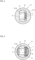
- Fig.3 shows a sectional view perpendicular to the flow direction of a slightly modified embodiment of the measuring device 1.
- the housing 18 of the measuring device is formed from a housing component 20 with high acoustic field impedance, for example made of metal, and further housing components 19 whose acoustic field impedance is rather low and which are made of plastic, for example.
- the waveguide 6 is held by the housing components 19 and, together with this and the housing component 20, closes the gap 15 between the waveguide 6 and the reflection surface 9 formed by the housing component 20 in a fluid-tight manner with respect to the measuring volume 28 carrying the fluid 27.
- This can be useful, for example, if the fluid layer 15 is to consist of a different fluid, for example a gel, than the fluid 27.
- the intermediate space 15 can be fluidically connected to at least one compensation volume (not shown), so that differences in the thermal expansion of the intermediate space 15 and the fluid layer 13 can be compensated. If the fluid layer 14 or a filler of the compensation volume is compressible or if a compressible solid body is used instead of the fluid layer 13, in addition to or as an alternative to a reception signal that causes wave propagation over the measuring volume 28, a reception signal can be detected which relates to a direct guidance of the guided wave from the ultrasonic transducer 2 to the ultrasonic transducer 3 within the waveguide 6.
- the transit time or phase position of this reception signal is predetermined by the phase velocity for the guided wave or the excited oscillation mode in the waveguide 6, which in turn correlates with the thickness D of the fluid layer 13 or of a solid body used instead of the fluid layer 13 between the waveguide 6 and the reflection surface 9.
- Fig.7 This connection is in Fig.7 where the X-axis 45 indicates the thickness D of the fluid layer 13 or the solid body used instead in mm and the Y-axis 46 indicates the phase velocity in m/s for the AO mode of a Lamb wave in the waveguide 6.
- the points shown in the diagram were calculated by simulation.
- the best fit line 47 at least for thicknesses where the value of the deviation ⁇ in the formula explained in the general part is close to 0, a linear best fit line 47 can be used with good accuracy to indicate the relationship between phase velocity c ph and thickness D. Since, in contrast to the case with reference to Fig.
- the intermediate space 15 could also be closed only to the measuring volume 28 and enable fluid exchange with the surroundings of the measuring device 1. This can, for example, enable the fluid layer 15 to be formed by condensation or a cooling fluid or the like located in the surroundings of the measuring device.
- Fig.4 shows a further modification of the measuring device 1, in which the housing comprises a tube as housing component 20, which accommodates the housing components 19 holding the other components.
- a housing component 21 for example a sheet metal, with high acoustic field impedance is used, which is opposite the waveguide 6.
- the housing components 19 hold a solid body 14 made of a material with a rather low acoustic field impedance, for example an unfilled plastic, which carries the waveguide 6 and the component 55 that forms the reflection surface 9.
- a contact layer or similar can be arranged between the solid body 14 and the reflection surface 9 or the rear surface 7 of the waveguide 6 in order to compensate for minor tolerance-related unevenness of the components mentioned. Due to the relatively low acoustic field impedance of the solid body 14, it acts in a similar way to the fluid layer 15 used in the previous embodiments, so that the same rule or formula can be used to determine the thickness D of the solid body 14 in the area between the waveguide 6 and the reflection surface 9 as also applies to the fluid layer 13 in the other embodiments.
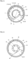
- the measuring device 1 is shown in Fig. 5 and 6 shown, which show sections through a measuring capsule meter in different separate cutting planes.
- the measuring volume 28 is formed by a measuring channel 35 which, apart from a channel inlet 36 and a channel outlet 37, is fluid-tight and runs around the fluid outlet 23 of the measuring device 1 in a torus-like manner.
- the fluid 27 is fed to the channel inlet 36 via a ramp 39 from a fluid inlet 22 which, when the measuring device is installed, is located below the measuring channel 35 and is connected to a connecting line (not shown).
- a transit time measurement or a measurement of the transit time difference for two propagation directions can be carried out to determine the flow.
- This basic structure of flow meters is known per se and is quite common, for example, for measuring capsule meters.
- an ultrasonic transducer 2 first excites a guided wave in the waveguide 6, which is guided directly within the waveguide and/or indirectly via the radiation of a pressure wave into the fluid 27 in the measuring volume 35 and/or indirectly via the radiation of a pressure wave into the fluid layer 13 in the intermediate space 15 to the ultrasonic transducer 3 in order to receive corresponding reception signals there.
- the described propagation paths can have significantly different propagation times, so that the received signals for these different propagation paths can be well separated in time.
- the waveguide 6 forms a side wall 38 of the measuring channel 35 and thus initially seals the measuring channel 35 off from the intermediate space 15 in a fluid-tight manner. A fluid exchange between the measuring channel 35 and the intermediate space 15 is thus only possible via the channel inlet 36 or the channel outlet 37.
- the waveguide 6 thus seals flush and fluid-tight with the Fig.5 lying bottom of the measuring channel 35, which separates the measuring channel from the fluid inlet 22, and which in Fig.5 above the image plane and in Fig.6 shown cover plate 44.
- the intermediate space 15 thus forms a bypass channel 24 which connects the fluid inflow 22 to the fluid outlet 23 via a connecting volume 40 located above the cover plate 44. A portion of the fluid supplied via the fluid inflow 22 can thus be guided via the bypass 24 past the measuring channel 35 to the fluid outlet 23.
- a further bypass channel 43 is additionally used, which is formed by the cover plate 44 having a recess so that the fluid can flow directly from the fluid inlet 22 into the connection volume 40.
- the connection volume 40 is connected to the fluid outlet 23 via throttle channels 41, which are delimited by partition walls 42, wherein the sum of the flow cross sections of the throttle channels 41 is smaller than the sum of the flow cross sections of the bypass channels 24 and 43.
- the portion of the fluid 27 fed to the measuring device that is guided via the bypass channels 24, 43 is primarily limited by the flow cross-sections of the throttle channels 41 and their number.
- the ratio of the flow cross-sections of the bypass channels 24 and 43 can thus be used to adjust the flow speed in the bypass channel 24 and thus in the intermediate space 15. This can be used, for example, to adjust the flow through the intermediate space 15 in such a way that deposits are avoided and at the same time no excessively high flow speeds occur, which could lead to turbulence in the fluid layer and thus to disruptions in the measuring operation.
- the flow direction in the bypass channel 24 or in the intermediate space 15 is essentially vertical, while the fluid flow in the measuring volume 35 and the direction of propagation of the guided wave or the pressure waves triggered by it are essentially horizontal. If travel times are thus determined for a propagation path that includes pressure waves in the intermediate space 15, these can be regarded as approximately independent of the flow velocity of the fluid in the measuring volume 35 or of the flow through the measuring device 1. This can make it possible in particular to estimate a speed of sound in the fluid layer 13 with just one measurement in one direction of propagation, i.e. on the basis of a single travel time or a single phase shift, for example at the receiving ultrasonic transducer 3, on the basis of which a temperature or a fluid composition can be determined, for example.
- a change in the speed of sound c f in the fluid layer 13 in the gap 15 between the waveguide 6 and the reflection surface 9 also affects the guidance of the guided wave in the waveguide 6 itself. It can therefore be advantageous to determine properties of the fluid forming the fluid layer 13 on the basis of a reception signal that relates to vibrations of the received ultrasonic transducer 2, 3 that are triggered directly by the guided wave excited by the other ultrasonic transducer 2, 3 in the waveguide 6.
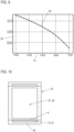
- curve 50 in Fig.8 the relationship between the speed of sound c f in the fluid layer 13, which occurred on the X-axis 48 in m/s, and the maximum amplitude of the received signal in V, which is plotted on the Y-axis 49 and achieved in a simulation of the measuring device. Due to the monotonic relationship shown, the speed of sound c f in the fluid and thus, for example, the fluid composition or temperature can be deduced directly from the amplitude of the received signal. A similar relationship also results for the density of the fluid layer 13 and the amplitude maximum of the received signal.
- the fluid layer 13 influences the phase velocity for the guided wave within the waveguide 6, the speed of sound c f in the fluid layer 13, its density or the other parameters mentioned above can also be deduced from the phase position or the position of a certain zero crossing.
- the curve 53 in Fig.9 by way of example, the relationship determined in a simulation between the speed of sound c f in the fluid layer 13 in m/s plotted on the X-axis 51 and the time of a specific zero crossing of the received signal plotted on the Y-axis 52 in ms. Due to the monotonic relationship, the speed of sound c f can be directly deduced from the time of the zero crossing.
- Fig.10 shows another possible embodiment of the measuring device 1, which differs from the previously discussed embodiments in that the housing 18 is one-piece, but is attached to the Fig.10 upper and lower ends of the measuring volume 28 delimited by the housing 18 have relatively thin side walls which form a respective waveguide 6.
- an intermediate space 15 can be delimited by a cover 54 which is placed on top and which receives the fluid layer 13 and forms the reflection surface.
- a solid body could also be used.
- the cover 54 and the fluid layer 13 or the solid body in the intermediate space 15 By using the cover 54 and the fluid layer 13 or the solid body in the intermediate space 15, the rear surface of the respective waveguide facing away from the measuring volume 28 is protected from environmental influences that could interfere with a measurement.
- the appropriate thickness of the fluid layer 13, as explained above it can be achieved that guided waves in the respective waveguide 6 remain essentially undisturbed.
- the cover 54 and the fluid layer 13 can also serve to support the waveguide 6 at high pressures in the measuring volume 28, so that even at high pressures there is essentially no deformation of the waveguide.
- a flexible fluid layer 13 or a solid body can be used to obtain pressure information based on the deformation of the waveguide 6, for example.
Landscapes
- Physics & Mathematics (AREA)
- General Physics & Mathematics (AREA)
- Biochemistry (AREA)
- Life Sciences & Earth Sciences (AREA)
- Chemical & Material Sciences (AREA)
- Analytical Chemistry (AREA)
- Health & Medical Sciences (AREA)
- General Health & Medical Sciences (AREA)
- Immunology (AREA)
- Pathology (AREA)
- Electromagnetism (AREA)
- Fluid Mechanics (AREA)
- Acoustics & Sound (AREA)
- Investigating Or Analyzing Materials By The Use Of Ultrasonic Waves (AREA)
Claims (14)
- Dispositif de mesure (1) destiné à déterminer une grandeur de mesure, comprenant un premier et un deuxième transducteur d'ultrasons (2, 3), un dispositif de commande (4), qui est conçu pour commander le premier transducteur d'ultrasons (2) de telle sorte que premier transducteur d'ultrasons (2) excite une onde guidée (5) ayant une fréquence d'oscillation f prédéfinie dans un guide d'ondes (6) du dispositif de mesure (1) couplé en oscillation avec le premier transducteur d'ultrasons (2), de telle sorte que l'onde guidée (5) se propage dans le guide d'ondes (6) parallèlement à une surface arrière (7) du guide d'ondes (6), le dispositif de commande (4) étant conçu pour déterminer la grandeur de mesure en fonction d'un signal reçu (10, 11, 12) du deuxième transducteur d'ultrasons (3), le signal reçu (10, 11, 12) dépendant des oscillations du deuxième transducteur d'ultrasons (3) provoquées directement et/ou indirectement par l'onde guidée (5),caractérisé en ce que la surface arrière (7) du guide d'ondes (6), au moins dans une portion de guidage d'ondes (8, 30, 31) du guide d'ondes (6), fait face à une surface de réflexion (9) du dispositif de mesure (1) et est espacée de celle-ci par un espace intermédiaire (15), le dispositif de mesure (1) étant conçu de telle sorte qu'au moins pendant la détermination de la grandeur de mesure, une couche de fluide (13) ou un corps solide (14) remplit l'espace intermédiaire (15) entre le guide d'ondes (6) et la surface de réflexion (9) au moins dans la portion de guidage d'ondes (8, 30, 31) du guide d'ondes (6), l'écart (16) entre la surface arrière (7) et la surface de réflexion (9) et ainsi l'épaisseur D de la couche de fluide (13) ou du corps solide (14) au moins dans la portion de guidage d'ondes (8, 30, 31) présentant la relation
 avec la fréquence d'oscillation f, la vitesse du son cf dans la couche de fluide (13) ou le corps solide (14) et la vitesse de phase cph dans le guide d'ondes (6), la variable de conception n étant un nombre entier positif et l'écart Δ étant d'une part égal à zéro ou d'autre part positif et inférieur à 0,7 ou à 0,5.
 - Dispositif de mesure selon la revendication 1, caractérisé en ce qu'il sert à mesurer une propriété d'un fluide (27) ou un écoulement du fluide (27), le guide d'ondes (6) étant disposé dans un volume de mesure (28) qui accueille ou guide le fluide (27) de telle sorte qu'une surface avant (29) du guide d'ondes (6), qui est à l'opposé de la surface arrière (7), entre en contact avec le fluide (27) dans le volume de mesure (28) en mode de mesure afin d'injecter dans le fluide (27) des ondes de pression (25) et/ou la surface avant (29) forme une paroi latérale (38) du volume de mesure (28).
- Dispositif de mesure selon la revendication 2, caractérisé en ce que l'espace intermédiaire (15) entre le guide d'ondes (6) et la surface de réflexion (9) est couplé fluidiquement au volume de mesure (28), de sorte que le fluide (27) introduit dans le volume de mesure (28) et/ou qui s'y trouve peut pénétrer dans l'espace intermédiaire (15) afin de former la couche de fluide (13) .
- Dispositif de mesure selon la revendication 3, caractérisé en ce qu'au moins une partie du volume de mesure (28) est formée par un canal de mesure (35), lequel est fermé de manière étanche aux fluides à l'exception d'une admission de canal (36) et d'une décharge de canal (37), une paroi latérale (38) du canal de mesure (35) est, au moins dans certaines portions, formée par la surface avant (29) du guide d'ondes (6), le canal de mesure (35) étant couplé fluidiquement à l'espace intermédiaire (15) entre la surface arrière (7) du guide d'ondes (6) et la surface de réflexion (9) exclusivement par le biais de l'admission de canal (36) et/ou de la décharge de canal (37).
- Dispositif de mesure selon la revendication 4, caractérisé en ce que le canal de mesure (35) circule autour d'une sortie de fluide (23) du dispositif de mesure (1) à la manière d'un tore, le fluide (27) pouvant être acheminé à l'admission de canal (36) par le biais d'une rampe (39) d'une arrivée de fluide (22) du dispositif de mesure (1) qui se trouve au-dessous du canal de mesure (35), notamment à l'état monté du dispositif de mesure (1), la décharge de canal (37) débouchant dans la sortie de fluide (23), l'espace intermédiaire (15) entre le guide d'ondes (6) et la surface de réflexion (9) formant un canal de contournement (24) qui entoure le canal de mesure (35) à la manière d'un tore au moins dans certaines portions et relie l'arrivée de fluide (22) à un volume de liaison (40) disposé au-dessus du canal de mesure (35), notamment à l'état monté du dispositif de mesure (1), lequel débouche dans la sortie de fluide (23).
- Dispositif de mesure selon la revendication 5, caractérisé en ce que le volume de liaison (40) est relié à la sortie de fluide (23) par le biais d'un canal d'étranglement (41) ou de plusieurs canaux d'étranglement (41), la section transversale d'écoulement du canal d'étranglement (41) ou la somme des sections transversales d'écoulement des canaux d'étranglement (41) étant inférieure à la section transversale d'écoulement du canal de contournement (24) formé par l'espace intermédiaire (15) ou que la somme des sections transversales d'écoulement de ce canal de contournement (24) et d'au moins un canal de contournement supplémentaire (43) qui relie l'arrivée de fluide (22) au volume de liaison (40).
- Dispositif de mesure selon la revendication 2 ou 3, caractérisé en ce que la portion de guidage d'ondes (8, 30, 31) du guide d'ondes (6) ou une portion partielle de la portion de guidage d'ondes (8, 30, 31) repose librement dans le volume de mesure (28) et peut ainsi être entourée par le courant du fluide (27).
- Dispositif de mesure selon la revendication 1 ou 2, caractérisé en ce que l'espace intermédiaire (15) entre le guide d'ondes (6) et la surface de réflexion (9), au moins dans la portion de guidage d'ondes (8, 30, 31) du guide d'ondes (6), est rempli par le corps solide (14) et/ou l'espace intermédiaire (15) est fermé de manière étanche aux fluides par rapport à l'environnement du dispositif de mesure (1), et notamment par rapport au volume de mesure (28), de sorte que l'épaisseur D du corps solide (14) ou de la couche de fluide (13) dépend de la pression au niveau de la ou d'une surface avant (29) du guide d'ondes tournée à l'opposé de la surface arrière (7), la pression étant déterminée comme la grandeur de mesure.
- Dispositif de mesure selon l'une des revendications 2 à 8, caractérisé en ce que le dispositif de commande (4) est conçu pour acquérir chronologiquement l'un après l'autre un premier et un deuxième signal reçu (10, 11, 12) du deuxième transducteur d'ultrasons (3) de telle sorte que le premier signal reçu (10, 11, 12) dépend des oscillations du deuxième transducteur d'ultrasons (3) qui sont excitées directement ou indirectement par une onde de pression excitée par l'onde guidée (5) dans la couche de fluide (13) ou dans le corps solide (14) ou qui sont excitées directement par l'onde guidée (5) dans le guide d'ondes (6), et que le deuxième signal reçu (10, 11, 12) dépend des oscillations du deuxième transducteur d'ultrasons (3) qui sont excitées directement ou indirectement par une onde de pression (25) excitée par l'onde guidée (5) dans le fluide (27) dans le volume de mesurer (28), et d'une part pour déterminer la grandeur de mesure en fonction du premier et du deuxième signal reçu (10, 11, 12) ou, d'autre part, pour déterminer la grandeur de mesure, notamment une pression dans le volume de mesure (28) et/ou une température et/ou densité de la couche de fluide (13) ou du corps solide (14) en fonction du premier signal reçu (10, 11, 12) et d'une grandeur de mesure supplémentaire, notamment une vitesse d'écoulement un ou débit volumique du fluide (27), en fonction du deuxième signal reçu (10, 11, 12).
- Dispositif de mesure selon l'une des revendications précédentes, caractérisé en ce que l'espace intermédiaire (15) entre le guide d'ondes (6) et la surface de réflexion (9) est fermé de manière étanche aux fluides, notamment par un boîtier (18) du dispositif de mesure (1), par rapport à l'environnement du dispositif de mesure (1) et/ou au volume de mesure (28).
- Dispositif de mesure selon l'une des revendications précédentes, caractérisé en ce que le dispositif de mesure (1) est conçu de telle sorte qu'au moins pendant la détermination de la grandeur de mesure, la ou une couche de fluide (13) supplémentaire ou le ou un corps solide (14) supplémentaire remplit un espace intermédiaire supplémentaire entre une portion de guidage d'ondes supplémentaire (31) de la surface arrière (7) du guide d'ondes (6) et une surface de réflexion supplémentaire, le guide d'ondes (6) étant soutenu dans une portion intermédiaire (32) du guide d'ondes (6) qui se trouve entre la portion de guidage d'ondes et la supplémentaire (30, 31) du guide d'ondes (6) par un composant (17) du dispositif de mesure (1), notamment le composant (20) qui forme la surface de réflexion (9), lequel présente une impédance de champ acoustique supérieure à celle de la couche de fluide (13) et/ou la supplémentaire ou du corps solide (14) et/ou du supplémentaire.
- Dispositif de mesure selon l'une des revendications précédentes, caractérisé en ce que le corps solide (14) ou la couche de fluide (13) et/ou le fluide (27) présentent une impédance de champ acoustique inférieure à celle du guide d'ondes (6) et/ou d'un composant (20) du dispositif de mesure (1) formant la surface de réflexion (9) et/ou en ce que le corps solide (14) ou la couche de fluide (13) présentent une impédance de champ acoustique d'au moins 10^5 Ns/m 3 ou d'au moins 10^6 Ns/m 3.
- Dispositif de mesure selon l'une des revendications précédentes, caractérisé en ce que d'une part la variable de conception n est au moins égale à 2 et/ou au maximum à 5, notamment égale à 2 ou égale à 3 et/ou en ce que d'autre part l'épaisseur (D) de la couche de fluide (13) ou du corps solide (14) est au minimum de 0,4 mm ou au minimum de 1,0 mm et/ou au maximum de 5 mm ou au maximum de 3,5 mm.
- Procédé de détermination d'une grandeur de mesure, un dispositif de mesure (1) étant utilisé, lequel comprend un premier et un deuxième transducteur d'ultrasons (2, 3) et un guide d'ondes (6), notamment un dispositif de mesure (1) selon l'une des revendications précédentes, le premier transducteur d'ultrasons (2) étant commandé par un dispositif de commande (4) du dispositif de mesure (1) de telle sorte qu'il excite une onde guidée (5) ayant une fréquence d'oscillation f prédéfinie dans le guide d'ondes (6), de telle sorte que l'onde guidée (5) se propage dans le guide d'ondes (6) parallèlement à une surface arrière (7) du guide d'ondes (6), le dispositif de commande (4) déterminant la grandeur de mesure en fonction d'un signal reçu (10, 11, 12) du deuxième transducteur d'ultrasons (3), le signal reçu (10, 11, 12) dépendant des oscillations du deuxième transducteur d'ultrasons (3) provoquées directement et/ou indirectement par l'onde guidée (5),caractérisé en ce que la surface arrière (7) du guide d'ondes (6), au moins dans une portion de guidage d'ondes (8, 30, 31) du guide d'ondes (6), fait face à une surface de réflexion (9) du dispositif de mesure (1) et est espacée de celle-ci par un espace intermédiaire (15), une couche de fluide (13) ou un corps solide (14), au moins pendant la détermination de la grandeur de mesure, remplissant l'espace intermédiaire (15) entre le guide d'ondes (6) et la surface de réflexion (9) au moins dans la portion de guidage d'ondes (8, 30, 31) du guide d'ondes (6), l'écart (16) entre la surface arrière (7) et la surface de réflexion (9) et ainsi l'épaisseur D de la couche de fluide (13) ou du corps solide (14) au moins dans la portion de guidage d'ondes (8, 30, 31) présentant la relation
 avec la fréquence d'oscillation f, la vitesse du son cf dans la couche de fluide (13) ou le corps solide (14) et la vitesse de phase cph dans le guide d'ondes, la variable de conception n étant un nombre entier positif et l'écart Δ étant d'une part égal à zéro ou d'autre part positif et inférieur à 0,7 ou à 0,5.
Applications Claiming Priority (1)
| Application Number | Priority Date | Filing Date | Title |
|---|---|---|---|
| DE102022105644.9A DE102022105644A1 (de) | 2022-03-10 | 2022-03-10 | Messeinrichtung und Verfahren zur Ermittlung einer Messgröße |
Publications (2)
| Publication Number | Publication Date |
|---|---|
| EP4242599A1 EP4242599A1 (fr) | 2023-09-13 |
| EP4242599B1 true EP4242599B1 (fr) | 2024-09-25 |
Family
ID=85477775
Family Applications (1)
| Application Number | Title | Priority Date | Filing Date |
|---|---|---|---|
| EP23160055.2A Active EP4242599B1 (fr) | 2022-03-10 | 2023-03-03 | Dispositif de mesure et procédé de détermination d'une grandeur de mesure |
Country Status (3)
| Country | Link |
|---|---|
| EP (1) | EP4242599B1 (fr) |
| CN (1) | CN116735704A (fr) |
| DE (1) | DE102022105644A1 (fr) |
Families Citing this family (1)
| Publication number | Priority date | Publication date | Assignee | Title |
|---|---|---|---|---|
| CN117156817A (zh) * | 2023-09-17 | 2023-12-01 | 深圳微电智控科技发展有限公司 | 多功能电力巡检仪 |
Family Cites Families (8)
| Publication number | Priority date | Publication date | Assignee | Title |
|---|---|---|---|---|
| US4336719A (en) * | 1980-07-11 | 1982-06-29 | Panametrics, Inc. | Ultrasonic flowmeters using waveguide antennas |
| US4590803A (en) * | 1984-06-28 | 1986-05-27 | Westinghouse Electric Corp. | Acoustic waveguide monitoring |
| DE102011076132B4 (de) | 2011-05-19 | 2023-03-23 | Endress+Hauser Flow Deutschland Ag | Vorrichtung und Verfahren zum Bestimmen von Eigenschaften eines Mediums |
| FR3006766B1 (fr) | 2013-06-05 | 2015-06-05 | Buerkert Werke Gmbh | Dispositif pour determiner des proprietes d'un milieu |
| FR3086388B1 (fr) | 2018-09-25 | 2021-06-04 | Buerkert Werke Gmbh & Co Kg | Moyen de mesure de fluide presentant un boitier de fluide, et procede de fabrication de boitier de fluide |
| JP7136685B2 (ja) * | 2018-12-27 | 2022-09-13 | 日立Geニュークリア・エナジー株式会社 | 気体音速の算出方法および算出装置 |
| DE102020002837A1 (de) * | 2020-05-12 | 2021-11-18 | Diehl Metering Gmbh | Verfahren zum Betrieb einer Messeinrichtung und Messeinrichtung |
| DE102020002834A1 (de) | 2020-05-12 | 2021-11-18 | Diehl Metering Gmbh | Messeinrichtung zur Ermittlung einer Fluidgröße |
-
2022
- 2022-03-10 DE DE102022105644.9A patent/DE102022105644A1/de not_active Withdrawn
-
2023
- 2023-03-03 EP EP23160055.2A patent/EP4242599B1/fr active Active
- 2023-03-09 CN CN202310225714.1A patent/CN116735704A/zh active Pending
Also Published As
| Publication number | Publication date |
|---|---|
| EP4242599A1 (fr) | 2023-09-13 |
| CN116735704A (zh) | 2023-09-12 |
| DE102022105644A1 (de) | 2023-09-14 |
Similar Documents
| Publication | Publication Date | Title |
|---|---|---|
| DE102011052670B4 (de) | Ultraschallwandlervorrichtung | |
| EP3577427B1 (fr) | Compteur à ultrasons et procédé d'acquisition d'une grandeur de débit | |
| EP3435041B1 (fr) | Module de mesure , dispositif de mesure et procédé permettant de déterminer une caractéristique de fluide | |
| EP1608939B1 (fr) | Dispositif permettant de determiner et/ou de surveiller le debit volumetrique et/ou massique d'un milieu | |
| EP3486630B1 (fr) | Dispositif de mesure permettant de déterminer une pression dans un volume de mesure | |
| EP2656017B1 (fr) | Élément de couplage d'un transducteur ultrasonique pour un débitmètre à ultrasons | |
| DE102011089685B4 (de) | Messanordnung zur Bestimmung eines Füllstands und/oder einer Konzentration einer Flüssigkeit | |
| DE102019124454A1 (de) | Fluidmesseinrichtung mit einem Fluidgehäuse und Verfahren zur Herstellung eines Fluidgehäuses | |
| EP2863215B1 (fr) | Dispositif de capteur destiné à détecter les propriétés d'un milieu fluidique | |
| DE102017110736A1 (de) | Messeinrichtung | |
| EP3855134B1 (fr) | Dispositif de mesure du débit d'écoulement d'un fluide | |
| DE102007062913A1 (de) | Ultraschallwandler zur Bestimmung und/oder Überwachung eines Durchflusses eines Messmediums durch ein Messrohr | |
| EP3246668B1 (fr) | Dispositif de mesure et procede de determination de la vitesse d'ecoulement d'un fluide s'ecoulant dans une conduite | |
| EP4242599B1 (fr) | Dispositif de mesure et procédé de détermination d'une grandeur de mesure | |
| EP3470799A1 (fr) | Dispositif de mesure permettant de déterminer une propriété de fluide | |
| DE4011923C2 (fr) | ||
| EP3910296B1 (fr) | Procédé de fonctionnement d'un dispositif de mesure et dispositif de mesure | |
| EP3940346B1 (fr) | Débitmètre et procédé de mesure du débit d'un fluide | |
| DE19535848C1 (de) | Vorrichtung zur Messung der akustischen Impedanz von flüssigen Medien | |
| EP1955019B1 (fr) | Dispositif de mesure à ultrasons pour déterminer et/ou surveiller l'écoulement volumique ou massique d'une substance dans une conduite tubulaire | |
| EP3405779A1 (fr) | Procédé de détermination acoustique de caractéristiques d'un milieu et dispositif de détermination acoustique de caractéristiques d'un milieu à l'aide d'un élément de réflexion | |
| EP3910295B1 (fr) | Dispositif de mesure pour déterminer une variable de fluide | |
| EP1046886B1 (fr) | Transducteur d'émission ou de réception pour un débitmètre à ultrasons | |
| DE202021103867U1 (de) | Fluidmesseinrichtung | |
| EP0905487B1 (fr) | Débitmètre |
Legal Events
| Date | Code | Title | Description |
|---|---|---|---|
| PUAI | Public reference made under article 153(3) epc to a published international application that has entered the european phase |
Free format text: ORIGINAL CODE: 0009012 |
|
| STAA | Information on the status of an ep patent application or granted ep patent |
Free format text: STATUS: THE APPLICATION HAS BEEN PUBLISHED |
|
| AK | Designated contracting states |
Kind code of ref document: A1 Designated state(s): AL AT BE BG CH CY CZ DE DK EE ES FI FR GB GR HR HU IE IS IT LI LT LU LV MC ME MK MT NL NO PL PT RO RS SE SI SK SM TR |
|
| STAA | Information on the status of an ep patent application or granted ep patent |
Free format text: STATUS: REQUEST FOR EXAMINATION WAS MADE |
|
| 17P | Request for examination filed |
Effective date: 20240216 |
|
| RBV | Designated contracting states (corrected) |
Designated state(s): AL AT BE BG CH CY CZ DE DK EE ES FI FR GB GR HR HU IE IS IT LI LT LU LV MC ME MK MT NL NO PL PT RO RS SE SI SK SM TR |
|
| GRAP | Despatch of communication of intention to grant a patent |
Free format text: ORIGINAL CODE: EPIDOSNIGR1 |
|
| STAA | Information on the status of an ep patent application or granted ep patent |
Free format text: STATUS: GRANT OF PATENT IS INTENDED |
|
| INTG | Intention to grant announced |
Effective date: 20240704 |
|
| GRAS | Grant fee paid |
Free format text: ORIGINAL CODE: EPIDOSNIGR3 |
|
| GRAA | (expected) grant |
Free format text: ORIGINAL CODE: 0009210 |
|
| STAA | Information on the status of an ep patent application or granted ep patent |
Free format text: STATUS: THE PATENT HAS BEEN GRANTED |
|
| AK | Designated contracting states |
Kind code of ref document: B1 Designated state(s): AL AT BE BG CH CY CZ DE DK EE ES FI FR GB GR HR HU IE IS IT LI LT LU LV MC ME MK MT NL NO PL PT RO RS SE SI SK SM TR |
|
| REG | Reference to a national code |
Ref country code: GB Ref legal event code: FG4D Free format text: NOT ENGLISH |
|
| REG | Reference to a national code |
Ref country code: CH Ref legal event code: EP |
|
| REG | Reference to a national code |
Ref country code: DE Ref legal event code: R096 Ref document number: 502023000183 Country of ref document: DE |
|
| REG | Reference to a national code |
Ref country code: IE Ref legal event code: FG4D Free format text: LANGUAGE OF EP DOCUMENT: GERMAN |
|
| REG | Reference to a national code |
Ref country code: LT Ref legal event code: MG9D |
|
| PG25 | Lapsed in a contracting state [announced via postgrant information from national office to epo] |
Ref country code: NO Free format text: LAPSE BECAUSE OF FAILURE TO SUBMIT A TRANSLATION OF THE DESCRIPTION OR TO PAY THE FEE WITHIN THE PRESCRIBED TIME-LIMIT Effective date: 20241225 |
|
| PG25 | Lapsed in a contracting state [announced via postgrant information from national office to epo] |
Ref country code: GR Free format text: LAPSE BECAUSE OF FAILURE TO SUBMIT A TRANSLATION OF THE DESCRIPTION OR TO PAY THE FEE WITHIN THE PRESCRIBED TIME-LIMIT Effective date: 20241226 Ref country code: FI Free format text: LAPSE BECAUSE OF FAILURE TO SUBMIT A TRANSLATION OF THE DESCRIPTION OR TO PAY THE FEE WITHIN THE PRESCRIBED TIME-LIMIT Effective date: 20240925 |
|
| PG25 | Lapsed in a contracting state [announced via postgrant information from national office to epo] |
Ref country code: BG Free format text: LAPSE BECAUSE OF FAILURE TO SUBMIT A TRANSLATION OF THE DESCRIPTION OR TO PAY THE FEE WITHIN THE PRESCRIBED TIME-LIMIT Effective date: 20240925 |
|
| PG25 | Lapsed in a contracting state [announced via postgrant information from national office to epo] |
Ref country code: LV Free format text: LAPSE BECAUSE OF FAILURE TO SUBMIT A TRANSLATION OF THE DESCRIPTION OR TO PAY THE FEE WITHIN THE PRESCRIBED TIME-LIMIT Effective date: 20240925 |
|
| PG25 | Lapsed in a contracting state [announced via postgrant information from national office to epo] |
Ref country code: RS Free format text: LAPSE BECAUSE OF FAILURE TO SUBMIT A TRANSLATION OF THE DESCRIPTION OR TO PAY THE FEE WITHIN THE PRESCRIBED TIME-LIMIT Effective date: 20241225 |
|
| REG | Reference to a national code |
Ref country code: NL Ref legal event code: MP Effective date: 20240925 |
|
| PG25 | Lapsed in a contracting state [announced via postgrant information from national office to epo] |
Ref country code: RS Free format text: LAPSE BECAUSE OF FAILURE TO SUBMIT A TRANSLATION OF THE DESCRIPTION OR TO PAY THE FEE WITHIN THE PRESCRIBED TIME-LIMIT Effective date: 20241225 Ref country code: NO Free format text: LAPSE BECAUSE OF FAILURE TO SUBMIT A TRANSLATION OF THE DESCRIPTION OR TO PAY THE FEE WITHIN THE PRESCRIBED TIME-LIMIT Effective date: 20241225 Ref country code: LV Free format text: LAPSE BECAUSE OF FAILURE TO SUBMIT A TRANSLATION OF THE DESCRIPTION OR TO PAY THE FEE WITHIN THE PRESCRIBED TIME-LIMIT Effective date: 20240925 Ref country code: GR Free format text: LAPSE BECAUSE OF FAILURE TO SUBMIT A TRANSLATION OF THE DESCRIPTION OR TO PAY THE FEE WITHIN THE PRESCRIBED TIME-LIMIT Effective date: 20241226 Ref country code: FI Free format text: LAPSE BECAUSE OF FAILURE TO SUBMIT A TRANSLATION OF THE DESCRIPTION OR TO PAY THE FEE WITHIN THE PRESCRIBED TIME-LIMIT Effective date: 20240925 Ref country code: BG Free format text: LAPSE BECAUSE OF FAILURE TO SUBMIT A TRANSLATION OF THE DESCRIPTION OR TO PAY THE FEE WITHIN THE PRESCRIBED TIME-LIMIT Effective date: 20240925 |
|
| PG25 | Lapsed in a contracting state [announced via postgrant information from national office to epo] |
Ref country code: NL Free format text: LAPSE BECAUSE OF FAILURE TO SUBMIT A TRANSLATION OF THE DESCRIPTION OR TO PAY THE FEE WITHIN THE PRESCRIBED TIME-LIMIT Effective date: 20240925 |
|
| PG25 | Lapsed in a contracting state [announced via postgrant information from national office to epo] |
Ref country code: IS Free format text: LAPSE BECAUSE OF FAILURE TO SUBMIT A TRANSLATION OF THE DESCRIPTION OR TO PAY THE FEE WITHIN THE PRESCRIBED TIME-LIMIT Effective date: 20250125 Ref country code: PT Free format text: LAPSE BECAUSE OF FAILURE TO SUBMIT A TRANSLATION OF THE DESCRIPTION OR TO PAY THE FEE WITHIN THE PRESCRIBED TIME-LIMIT Effective date: 20250127 |
|
| PG25 | Lapsed in a contracting state [announced via postgrant information from national office to epo] |
Ref country code: RO Free format text: LAPSE BECAUSE OF FAILURE TO SUBMIT A TRANSLATION OF THE DESCRIPTION OR TO PAY THE FEE WITHIN THE PRESCRIBED TIME-LIMIT Effective date: 20240925 Ref country code: SM Free format text: LAPSE BECAUSE OF FAILURE TO SUBMIT A TRANSLATION OF THE DESCRIPTION OR TO PAY THE FEE WITHIN THE PRESCRIBED TIME-LIMIT Effective date: 20240925 |
|
| PG25 | Lapsed in a contracting state [announced via postgrant information from national office to epo] |
Ref country code: ES Free format text: LAPSE BECAUSE OF FAILURE TO SUBMIT A TRANSLATION OF THE DESCRIPTION OR TO PAY THE FEE WITHIN THE PRESCRIBED TIME-LIMIT Effective date: 20240925 |
|
| PG25 | Lapsed in a contracting state [announced via postgrant information from national office to epo] |
Ref country code: EE Free format text: LAPSE BECAUSE OF FAILURE TO SUBMIT A TRANSLATION OF THE DESCRIPTION OR TO PAY THE FEE WITHIN THE PRESCRIBED TIME-LIMIT Effective date: 20240925 |
|
| PG25 | Lapsed in a contracting state [announced via postgrant information from national office to epo] |
Ref country code: CZ Free format text: LAPSE BECAUSE OF FAILURE TO SUBMIT A TRANSLATION OF THE DESCRIPTION OR TO PAY THE FEE WITHIN THE PRESCRIBED TIME-LIMIT Effective date: 20240925 Ref country code: PL Free format text: LAPSE BECAUSE OF FAILURE TO SUBMIT A TRANSLATION OF THE DESCRIPTION OR TO PAY THE FEE WITHIN THE PRESCRIBED TIME-LIMIT Effective date: 20240925 |
|
| PG25 | Lapsed in a contracting state [announced via postgrant information from national office to epo] |
Ref country code: IT Free format text: LAPSE BECAUSE OF FAILURE TO SUBMIT A TRANSLATION OF THE DESCRIPTION OR TO PAY THE FEE WITHIN THE PRESCRIBED TIME-LIMIT Effective date: 20240925 Ref country code: SK Free format text: LAPSE BECAUSE OF FAILURE TO SUBMIT A TRANSLATION OF THE DESCRIPTION OR TO PAY THE FEE WITHIN THE PRESCRIBED TIME-LIMIT Effective date: 20240925 |
|
| REG | Reference to a national code |
Ref country code: DE Ref legal event code: R097 Ref document number: 502023000183 Country of ref document: DE |
|
| PG25 | Lapsed in a contracting state [announced via postgrant information from national office to epo] |
Ref country code: DK Free format text: LAPSE BECAUSE OF FAILURE TO SUBMIT A TRANSLATION OF THE DESCRIPTION OR TO PAY THE FEE WITHIN THE PRESCRIBED TIME-LIMIT Effective date: 20240925 |
|
| PLBE | No opposition filed within time limit |
Free format text: ORIGINAL CODE: 0009261 |
|
| STAA | Information on the status of an ep patent application or granted ep patent |
Free format text: STATUS: NO OPPOSITION FILED WITHIN TIME LIMIT |
|
| 26N | No opposition filed |
Effective date: 20250626 |
|
| PG25 | Lapsed in a contracting state [announced via postgrant information from national office to epo] |
Ref country code: SE Free format text: LAPSE BECAUSE OF FAILURE TO SUBMIT A TRANSLATION OF THE DESCRIPTION OR TO PAY THE FEE WITHIN THE PRESCRIBED TIME-LIMIT Effective date: 20240925 |
|
| REG | Reference to a national code |
Ref country code: DE Ref legal event code: R119 Ref document number: 502023000183 Country of ref document: DE |
|
| PG25 | Lapsed in a contracting state [announced via postgrant information from national office to epo] |
Ref country code: MC Free format text: LAPSE BECAUSE OF FAILURE TO SUBMIT A TRANSLATION OF THE DESCRIPTION OR TO PAY THE FEE WITHIN THE PRESCRIBED TIME-LIMIT Effective date: 20240925 |
|
| PG25 | Lapsed in a contracting state [announced via postgrant information from national office to epo] |
Ref country code: LU Free format text: LAPSE BECAUSE OF NON-PAYMENT OF DUE FEES Effective date: 20250303 |
|
| REG | Reference to a national code |
Ref country code: BE Ref legal event code: MM Effective date: 20250331 |
|
| PG25 | Lapsed in a contracting state [announced via postgrant information from national office to epo] |
Ref country code: DE Free format text: LAPSE BECAUSE OF NON-PAYMENT OF DUE FEES Effective date: 20251001 |
|
| PG25 | Lapsed in a contracting state [announced via postgrant information from national office to epo] |
Ref country code: HR Free format text: LAPSE BECAUSE OF FAILURE TO SUBMIT A TRANSLATION OF THE DESCRIPTION OR TO PAY THE FEE WITHIN THE PRESCRIBED TIME-LIMIT Effective date: 20240925 Ref country code: FR Free format text: LAPSE BECAUSE OF NON-PAYMENT OF DUE FEES Effective date: 20250331 |
|
| PG25 | Lapsed in a contracting state [announced via postgrant information from national office to epo] |
Ref country code: BE Free format text: LAPSE BECAUSE OF NON-PAYMENT OF DUE FEES Effective date: 20250331 |
|
| PG25 | Lapsed in a contracting state [announced via postgrant information from national office to epo] |
Ref country code: IE Free format text: LAPSE BECAUSE OF NON-PAYMENT OF DUE FEES Effective date: 20250303 |
|
| PGFP | Annual fee paid to national office [announced via postgrant information from national office to epo] |
Ref country code: AT Payment date: 20260301 Year of fee payment: 4 |