EP4242644A1 - Inspektionssystem und verfahren zur inspektion einer optischen oberfläche eines laserscanners - Google Patents
Inspektionssystem und verfahren zur inspektion einer optischen oberfläche eines laserscanners Download PDFInfo
- Publication number
- EP4242644A1 EP4242644A1 EP22209031.8A EP22209031A EP4242644A1 EP 4242644 A1 EP4242644 A1 EP 4242644A1 EP 22209031 A EP22209031 A EP 22209031A EP 4242644 A1 EP4242644 A1 EP 4242644A1
- Authority
- EP
- European Patent Office
- Prior art keywords
- laser scanner
- optical
- light
- inspection system
- optical surface
- Prior art date
- Legal status (The legal status is an assumption and is not a legal conclusion. Google has not performed a legal analysis and makes no representation as to the accuracy of the status listed.)
- Pending
Links
Images





Classifications
-
- G—PHYSICS
- G01—MEASURING; TESTING
- G01N—INVESTIGATING OR ANALYSING MATERIALS BY DETERMINING THEIR CHEMICAL OR PHYSICAL PROPERTIES
- G01N21/00—Investigating or analysing materials by the use of optical means, i.e. using sub-millimetre waves, infrared, visible or ultraviolet light
- G01N21/84—Systems specially adapted for particular applications
- G01N21/88—Investigating the presence of flaws or contamination
- G01N21/95—Investigating the presence of flaws or contamination characterised by the material or shape of the object to be examined
- G01N21/958—Inspecting transparent materials or objects, e.g. windscreens
-
- G—PHYSICS
- G01—MEASURING; TESTING
- G01N—INVESTIGATING OR ANALYSING MATERIALS BY DETERMINING THEIR CHEMICAL OR PHYSICAL PROPERTIES
- G01N21/00—Investigating or analysing materials by the use of optical means, i.e. using sub-millimetre waves, infrared, visible or ultraviolet light
- G01N21/84—Systems specially adapted for particular applications
- G01N21/88—Investigating the presence of flaws or contamination
- G01N21/95—Investigating the presence of flaws or contamination characterised by the material or shape of the object to be examined
-
- G—PHYSICS
- G01—MEASURING; TESTING
- G01N—INVESTIGATING OR ANALYSING MATERIALS BY DETERMINING THEIR CHEMICAL OR PHYSICAL PROPERTIES
- G01N21/00—Investigating or analysing materials by the use of optical means, i.e. using sub-millimetre waves, infrared, visible or ultraviolet light
- G01N21/84—Systems specially adapted for particular applications
- G01N21/88—Investigating the presence of flaws or contamination
- G01N21/8851—Scan or image signal processing specially adapted therefor, e.g. for scan signal adjustment, for detecting different kinds of defects, for compensating for structures, markings, edges
-
- B—PERFORMING OPERATIONS; TRANSPORTING
- B23—MACHINE TOOLS; METAL-WORKING NOT OTHERWISE PROVIDED FOR
- B23K—SOLDERING OR UNSOLDERING; WELDING; CLADDING OR PLATING BY SOLDERING OR WELDING; CUTTING BY APPLYING HEAT LOCALLY, e.g. FLAME CUTTING; WORKING BY LASER BEAM
- B23K26/00—Working by laser beam, e.g. welding, cutting or boring
- B23K26/70—Auxiliary operations or equipment
- B23K26/702—Auxiliary equipment
- B23K26/707—Auxiliary equipment for monitoring laser beam transmission optics
-
- G—PHYSICS
- G01—MEASURING; TESTING
- G01M—TESTING STATIC OR DYNAMIC BALANCE OF MACHINES OR STRUCTURES; TESTING OF STRUCTURES OR APPARATUS, NOT OTHERWISE PROVIDED FOR
- G01M11/00—Testing of optical apparatus; Testing structures by optical methods not otherwise provided for
- G01M11/02—Testing optical properties
- G01M11/0242—Testing optical properties by measuring geometrical properties or aberrations
- G01M11/0278—Detecting defects of the object to be tested, e.g. scratches or dust
-
- G—PHYSICS
- G01—MEASURING; TESTING
- G01N—INVESTIGATING OR ANALYSING MATERIALS BY DETERMINING THEIR CHEMICAL OR PHYSICAL PROPERTIES
- G01N21/00—Investigating or analysing materials by the use of optical means, i.e. using sub-millimetre waves, infrared, visible or ultraviolet light
- G01N21/84—Systems specially adapted for particular applications
- G01N21/88—Investigating the presence of flaws or contamination
- G01N21/8806—Specially adapted optical and illumination features
-
- G—PHYSICS
- G01—MEASURING; TESTING
- G01N—INVESTIGATING OR ANALYSING MATERIALS BY DETERMINING THEIR CHEMICAL OR PHYSICAL PROPERTIES
- G01N21/00—Investigating or analysing materials by the use of optical means, i.e. using sub-millimetre waves, infrared, visible or ultraviolet light
- G01N21/84—Systems specially adapted for particular applications
- G01N21/88—Investigating the presence of flaws or contamination
- G01N21/94—Investigating contamination, e.g. dust
-
- G—PHYSICS
- G01—MEASURING; TESTING
- G01N—INVESTIGATING OR ANALYSING MATERIALS BY DETERMINING THEIR CHEMICAL OR PHYSICAL PROPERTIES
- G01N21/00—Investigating or analysing materials by the use of optical means, i.e. using sub-millimetre waves, infrared, visible or ultraviolet light
- G01N21/84—Systems specially adapted for particular applications
- G01N21/88—Investigating the presence of flaws or contamination
- G01N21/8851—Scan or image signal processing specially adapted therefor, e.g. for scan signal adjustment, for detecting different kinds of defects, for compensating for structures, markings, edges
- G01N2021/8887—Scan or image signal processing specially adapted therefor, e.g. for scan signal adjustment, for detecting different kinds of defects, for compensating for structures, markings, edges based on image processing techniques
-
- G—PHYSICS
- G01—MEASURING; TESTING
- G01N—INVESTIGATING OR ANALYSING MATERIALS BY DETERMINING THEIR CHEMICAL OR PHYSICAL PROPERTIES
- G01N21/00—Investigating or analysing materials by the use of optical means, i.e. using sub-millimetre waves, infrared, visible or ultraviolet light
- G01N21/84—Systems specially adapted for particular applications
- G01N21/88—Investigating the presence of flaws or contamination
- G01N21/94—Investigating contamination, e.g. dust
- G01N2021/945—Liquid or solid deposits of macroscopic size on surfaces, e.g. drops, films, or clustered contaminants
-
- G—PHYSICS
- G01—MEASURING; TESTING
- G01N—INVESTIGATING OR ANALYSING MATERIALS BY DETERMINING THEIR CHEMICAL OR PHYSICAL PROPERTIES
- G01N21/00—Investigating or analysing materials by the use of optical means, i.e. using sub-millimetre waves, infrared, visible or ultraviolet light
- G01N21/84—Systems specially adapted for particular applications
- G01N21/88—Investigating the presence of flaws or contamination
- G01N21/95—Investigating the presence of flaws or contamination characterised by the material or shape of the object to be examined
- G01N2021/9511—Optical elements other than lenses, e.g. mirrors
-
- G—PHYSICS
- G01—MEASURING; TESTING
- G01N—INVESTIGATING OR ANALYSING MATERIALS BY DETERMINING THEIR CHEMICAL OR PHYSICAL PROPERTIES
- G01N21/00—Investigating or analysing materials by the use of optical means, i.e. using sub-millimetre waves, infrared, visible or ultraviolet light
- G01N21/84—Systems specially adapted for particular applications
- G01N21/88—Investigating the presence of flaws or contamination
- G01N21/95—Investigating the presence of flaws or contamination characterised by the material or shape of the object to be examined
- G01N21/958—Inspecting transparent materials or objects, e.g. windscreens
- G01N2021/9583—Lenses
-
- G—PHYSICS
- G01—MEASURING; TESTING
- G01N—INVESTIGATING OR ANALYSING MATERIALS BY DETERMINING THEIR CHEMICAL OR PHYSICAL PROPERTIES
- G01N2201/00—Features of devices classified in G01N21/00
- G01N2201/02—Mechanical
- G01N2201/022—Casings
-
- G—PHYSICS
- G01—MEASURING; TESTING
- G01N—INVESTIGATING OR ANALYSING MATERIALS BY DETERMINING THEIR CHEMICAL OR PHYSICAL PROPERTIES
- G01N2201/00—Features of devices classified in G01N21/00
- G01N2201/06—Illumination; Optics
- G01N2201/062—LED's
-
- G—PHYSICS
- G01—MEASURING; TESTING
- G01N—INVESTIGATING OR ANALYSING MATERIALS BY DETERMINING THEIR CHEMICAL OR PHYSICAL PROPERTIES
- G01N2201/00—Features of devices classified in G01N21/00
- G01N2201/08—Optical fibres; light guides
Definitions
- the present disclosure relates generally to laser scanners and, in particular, to automated laser scanner lens inspection systems.
- Laser scanners are used in various ways during the manufacture of components for vehicles, such as, for example aircraft components.
- laser scanners can be used for laser ablation of the surfaces of components to increase adhesive capabilities of the surfaces of the components in order to make paint adhere to the surfaces of the components better.
- the optical surface of the laser scanner In order to ensure a high quality ablation of the surface, the optical surface of the laser scanner must be substantially unobstructed. That is, the outer portion of the optical surface at which the laser egresses the laser scanner must be substantially free from debris such that the laser light can egress the optical surface without being significantly deflected by debris on the optical surface.
- Example implementations of the present disclosure are directed to an inspection system for inspecting an optical surface of a laser scanner.
- the optical surface of the laser scanner is maneuvered to the inspection system (or vice versa) for detecting debris on the optical surface of the laser scanner.
- the optical surface is the egress point of the laser in the laser scanner.
- the inspection system comprises a directional optical source, such as a light emitting diode (LED), configured to emit a light beam across the optical surface, but the light beam does not intersect with the optical surface.
- the light beam extending across, and just above, the surface of the optical surface will impact on any debris in its path that is on the optical surface and deflect out.
- LED light emitting diode
- the inspection system further comprises an optical detector, such as a camera, configured to capture light deflected from the optical surface.
- an optical detector such as a camera
- the optical detector will capture images of the light and determine, from the images, if the amount of debris on the optical surface is above a predefined threshold. If it is, a computer associated with the inspection system will generate feedback to alert a user of the presence of the debris so that the optical surface can be cleaned.
- the present disclosure thus includes, without limitation, the following example implementations.
- Some example implementations provide an inspection system for inspecting an optical surface of a laser scanner, the inspection system comprising: a directional optical source configured to emit a light beam when at least one of the laser scanner or the inspection system are moved to a position in which a beam axis of the directional optical source extends across but does not intersect the optical surface of the laser scanner, between the optical surface of the laser scanner and an optical detector, the directional optical source configured to emit the light beam across the optical surface of the laser scanner so that light from the light beam is incident on debris disposed on the optical surface of the laser scanner; the optical detector configured to collect the light to form an image that indicates presence of the debris on the optical surface of the laser scanner; and a computer configured to generate feedback to alert a user of the presence of the debris.
- Some example implementations provide a method of inspecting an optical surface of a laser scanner with an inspection system that includes a directional optical source and an optical detector, the method comprising: moving at least one of the laser scanner or the inspection system to a position in which a beam axis of the directional optical source extends across but does not intersect the optical surface of the laser scanner, between the optical surface of the laser scanner and the optical detector; emitting a light beam from the directional optical source, across the optical surface of the laser scanner so that light from the light beam is incident on debris disposed on the optical surface of the laser scanner; collecting the light at the optical detector to form an image that indicates presence of the debris on the optical surface of the laser scanner; and generating feedback to alert a user of the presence of the debris.
- references to first, second or the like should not be construed to imply a particular order.
- a feature described as being above another feature may instead be below, and vice versa; and similarly, features described as being to the left of another feature else may instead be to the right, and vice versa.
- reference may be made herein to quantitative measures, values, geometric relationships or the like unless otherwise stated, any one or more if not all of these may be absolute or approximate to account for acceptable variations that may occur, such as those due to engineering tolerances or the like.
- Example implementations of the present disclosure relate generally to vehicular engineering and, in particular, to one or more of the design, construction, operation or use of vehicles.
- a vehicle is a machine designed as an instrument of conveyance by land, water or air.
- a vehicle designed and configurable to fly may at times be referred to as an aerial vehicle, an aircraft or the like.
- suitable vehicles include any of a number of different types of ground vehicles (e.g., motor vehicles, railed vehicles), watercraft, amphibious vehicles, spacecraft and the like.
- a vehicle generally includes a basic structure, and a propulsion system coupled to the basic structure.
- the basic structure is the main supporting structure of the vehicle to which other components are attached.
- the basic structure is the load-bearing framework of the vehicle that structurally supports the vehicle in its construction and function.
- the basic structure may be referred to as a chassis, an airframe or the like.
- the propulsion system includes one or more engines or motors configured to power one or more propulsors to generate propulsive forces that cause the vehicle to move.
- a propulsor is any of a number of different means of converting power into a propulsive force. Examples of suitable propulsors include rotors, propellers, wheels and the like.
- the propulsion system includes a drivetrain configured to deliver power from the engines / motors to the propulsors.
- the engines / motors and drivetrain may in some contexts be referred to as the powertrain of the vehicle.
- FIG. 1 illustrates one type of vehicle, namely, an aircraft 100 that may benefit from example implementations of the present disclosure.
- the aircraft includes a basic structure with an airframe 102 including a fuselage 104.
- the airframe also includes wings 106 that extend from opposing sides of the fuselage, an empennage or tail assembly 108 at a rear end of the fuselage, and the tail assembly includes stabilizers 110.
- the aircraft also includes a plurality of high-level systems 112 such as a propulsion system.
- the propulsion system includes two wing-mounted engines 114 configured to power propulsors to generate propulsive forces that cause the aircraft to move.
- the propulsion system can include other arrangements, for example, engines carried by other portions of the aircraft including the fuselage and/or the tail.
- the high-level systems may also include an electrical system 116, hydraulic system 118 and/or environmental system 120. Any number of other systems may be included.
- example implementations of the present disclosure relate generally to vehicular engineering and, in particular, to one or more of the design, construction, operation or use of vehicles such as aircraft 100.
- example implementations may be used in the context of an aircraft manufacturing and service method 200.
- the example method may include specification and design 202 of the aircraft, manufacturing sequence and processing planning 204 and material procurement 206.
- component and subassembly manufacturing 208 and system integration 210 of the aircraft takes place.
- the aircraft may go through certification and delivery 212 in order to be placed in service 214.
- the aircraft may be scheduled for maintenance and service (which may also include modification, reconfiguration, refurbishment or the like).
- a system integrator may include for example any number of aircraft manufacturers and major-system subcontractors; a third party may include for example any number of vendors, subcontractors and suppliers; and an operator may include for example an airline, leasing company, military entity, service organization or the like.
- computers are often used throughout the method 200; and in this regard, a "computer” is generally a machine that is programmable or programmed to perform functions or operations.
- the method as shown makes use of a number of example computers. These computers include computers 216, 218 used for the specification and design 202 of the aircraft, and the manufacturing sequence and processing planning 204.
- the method may also make use of computers 220 during component and subassembly manufacturing 208, which may also make use of computer numerical control (CNC) machines, machine tools 222 or other robotics that are controlled by computers 224.
- the machine tools may include one or more lasers or laser scanners 230 that are generally configured to perform laser ablation of surfaces of components and other tasks.
- computers 226 may be used while the aircraft is in service 214, as well as during maintenance and service; and as suggested in FIG. 1 , the aircraft may itself include one or more computers 228 as part of or separate from its electrical system 116.
- a number of the computers 216-228 used in the method 200 may be co-located or directly coupled to one another, or in some examples, various ones of the computers may communicate with one another across one or more computer networks. Further, although shown as part of the method, it should be understood that any one or more of the computers may function or operate separate from the method, without regard to any of the other computers. It should also be understood that the method may include one or more additional or alternative computers than those shown in FIG. 2 .
- Example implementations of the present disclosure may be implemented throughout the aircraft manufacturing and service method 200, but are particularly well suited for implementation during production, and while in service.
- some example implementations provide inspection systems and methods for inspecting an optical surface of a laser scanner.
- FIG. 3 illustrates a block diagram of an inspection system 300 for inspecting an optical surface 306 such as a lens of a laser scanner 230, according to some implementations of the present disclosure.
- the inspection system includes one or more of each of a number of components such as a directional optical source 302 (two shown), an optical detector 310, and a computer 308.
- FIG. 3 further illustrates how the directional optical source and optical detector interact with debris D on an optical surface 306, for example, an optical surface of a laser scanner 230 used in the process described with respect to FIG. 2 .
- One purpose of the inspection system is to detect the debris on the optical surface.
- the directional optical source is configured to emit a light beam across the optical surface when at least one of the laser scanner or the inspection system are moved to a position in which a beam axis of the directional optical source extends across, but does not intersect the optical surface of the laser scanner. Furthermore, in the position to which the at least one of the laser scanner or the inspection system is moved, the directional optical source is positioned on a perimeter of the optical surface of the laser scanner.
- the light beam(s) is emitted between the optical surface 306 of the laser scanner 230 and the optical detector 310.
- the directional optical source 302 is configured to emit the light beam across the optical surface of the laser scanner so that light from the light beam(s) is incident on debris D disposed on the optical surface of the laser scanner. When light from the light beam hits the debris, it deflects off the debris toward the optical detector.
- the optical detector is configured to collect the light that is deflected off the debris to form an image that indicates presence of the debris on the optical surface of the laser scanner.
- the optical detector 310 comprises a camera, or other suitable light capturing device, configured to collect light deflected off the debris D to form an image that indicates presence of the debris on the optical surface.
- the inspection system 300 includes a computer 308 configured to generate feedback to alert a user of the presence of the debris.
- the computer may also be configured to control various aspects of the optical detector, including processing one or more of the captured images, and the directional optical source 302.
- FIGS. 4A , 4B , and 4C illustrate various views of an inspection system 400 that may correspond to inspection system 300, according to some example implementations.
- the inspection system includes a housing 402 in which the optical detector 310 is contained.
- the housing defines a housing aperture 404, and the directional optical source 302 (not shown) is positioned on a perimeter of the housing aperture.
- FIG. 4B illustrates a close-up exterior view of the inspection system 400.
- the directional optical source 302 may comprise any suitable light source.
- the directional optical source includes an optical fiber configured to carry light to a fiber tip at which a light beam is emitted.
- the fiber tip is positioned on the perimeter of the housing aperture 404 so that the light beam is emitted across the housing aperture.
- the directional optical source comprises one or more light emitting diodes (LEDS).
- the directional optical source is contained in the housing 402 of the inspection system 400.
- the directional optical source 302 i.e., the fiber optic cables, if used
- the directional optical source can be integrated within the housing, including around a perimeter of the housing aperture 404 such that light emitted by the directional optical source is emitted across the opening of the housing aperture.
- the directional optical source In the position to which the at least one of the laser scanner 230 or the inspection system is moved, the directional optical source is positioned over the housing aperture and exposed to the optical detector 310 contained within the housing. In this position, the housing aperture is covered by the laser scanner to block ambient light from entering the housing through the housing aperture.
- the inspection system 400 comprises a plurality of directional optical sources 302 positioned and distributed around the perimeter of the housing aperture 404.
- beam axes of respective ones of the plurality of directional optical sources extend across but do not intersect the optical surface 306 of the laser scanner.
- respective ones of the plurality of directional optical sources are configured to emit light beams across the optical surface of the laser scanner so that light from one or more of the light beams is incident on the debris D.
- the light beams can be emitted individually for respective ones of the light beams to form respective images, one or more of which indicates the presence of debris on the optical surface of the laser scanner.
- the housing aperture has any suitable shape.
- the perimeter of the housing aperture has a circular, square, rectangular, triangular, pentagonal, or hexagonal shape.
- the directional optical source comprises a plurality of directional optical sources distributed around all the sides of the perimeter of the optical aperture.
- the housing aperture 404 is configured to be aligned with the optical surface 306 of a laser scanner 230, such as the one shown in FIG. 5A and FIG. 5B , that is moved to the system 400.
- a central axis of the housing aperture can be substantially aligned with a central axis of the optical surface.
- the housing aperture has a diameter, width, and/or length, that is equal to or greater than a diameter, width, or length of the optical surface. With the housing aperture being aligned with the optical surface and the housing aperture having a larger diameter, width, and/or length than the optical surface, this allows the directional optical source to emit one or more beams that travel across the entire diameter, width, or length of the optical surface.
- the inspection system 400 can comprise a mount 406 on an outer surface of the housing 402 over the housing aperture 404.
- the mount defines a mount aperture 408 that overlaps the housing aperture.
- a central axis of the mount aperture aligns with a central axis of the housing aperture.
- the mount aperture and housing aperture can have any suitable shape, and their respective shapes can be different or the same shape(s).
- the housing aperture can have a circular shape and the mount aperture can have a square or rectangular shape.
- the directional optical source 302 can be positioned on a perimeter of the mount aperture 408 and thereby the perimeter of the housing aperture 404.
- the directional optical source can include optical fiber configured to carry light to a fiber tip at which a light beam is emitted.
- the fiber tip can be or positioned around the perimeter of the mount aperture (e.g., integrated within the mount 406 on the perimeter of the mount aperture) so that the light beam is emitted across the mount aperture and thereby the housing aperture.
- the directional optical source 302 can comprise a plurality of directional optical sources, each comprising a fiber tip.
- each of the fiber tips can be integrated into and along a perimeter of the mount aperture 408.
- beam axes of respective ones of the plurality of directional optical sources extend across but do not intersect the optical surface 306 of the laser scanner 230.
- respective ones of the plurality of directional optical sources are configured to emit light beams across the optical surface of the laser scanner so that light from one or more of the light beams is incident on the debris.
- the light beams from the plurality of directional optical sources are emitted individually in a predefined sequence.
- the light is collected individually by the optical detector 310 for respective ones of the light beams to form respective images, one or more of which indicates the presence of the debris on the optical surface of the laser scanner.
- the laser scanner 230 and/or inspection system 400 is moved so that the optical surface 306 is positioned over the mount aperture 408 and exposed to the optical detector 310 contained in the housing 402. In this way, the mount aperture is covered by the laser scanner to block ambient light from entering the housing through the mount aperture and the housing aperture.
- the directional optical source 302 is activated (as described above) to emit beam(s) of light across the mount aperture and thereby the optical surface.
- a beam axis of the directional optical source extends across but does not intersect the optical surface of the laser scanner.
- the beam of light extends across the optical surface between the optical surface and the optical detector.
- the directional optical source is configured to emit the light beam across the optical surface of the laser scanner so that light from the light beam is incident on debris disposed on the optical surface.
- FIG. 5A illustrates an example laser scanner 230 according to some implementations of the present disclosure.
- the laser scanner can be attached to a movable structure, such as for example, a moveable arm, a robotic arm, crane, or other suitable movable structure. Via the moveable structure, the laser scanner can be brought to the inspection system 400 like the one mounted on the beam/wall in FIG. 4A .
- the laser scanner is used for any suitable purpose, including laser ablation of surfaces.
- the optical surface 306 described herein can be a surface of a lens of the laser scanner through which laser beams are emitted.
- FIG. 5B illustrates a close-up of the optical surface 306 of the laser scanner 230 illustrated in FIG. 5A .
- the inspection system 400 of the present disclosure is configured to inspect any suitably shaped and sized optical surface.
- the optical surface in FIG. 5B is illustrated as being circular, the methods and devices of the present subject matter can be used to inspect optical surfaces of any size or shape as long as the diameter, length, and/or width is less than or equal to the diameter, length, and/or width of the housing aperture 404 or mount aperture 408.
- At least one of the laser scanner 230 or the inspection system 400 is moved so that the optical surface 306 is positioned over the housing aperture 404, or the mount aperture 408, if the mount 406 is attached to the housing 402.
- the optical surface is then exposed to the optical detector 310 (described further hereinbelow) contained within the housing, and so that the housing aperture and/or the mount aperture is covered by the laser scanner to block ambient light from entering the housing through the housing aperture and/or the mount aperture. This is done to ensure only light from the directional optical source 302 is detected by the optical detector.
- the inspection system 400 is then triggered to begin inspecting the optical surface 306, one or more beams of light are emitted by directional optical source 302, across the housing aperture 404 and/or mount aperture 408 and thereby across and above the optical surface. The same process occurs regardless if the inspection system is moved to the laser scanner or vice-versa. The light deflected by the debris D is then captured by the optical detector 310.
- the inspection system 400 comprises a computer 308 either integrated within the system or as a separate workstation.
- the inspection system mounted on the wall in FIG. 4A can have a computer workstation attached to it.
- the computer can be a device separate from the inspection system at a distance and connected to the inspection system via a network (e.g., via the Internet, a wireless carrier communication network, via Bluetooth ® , via Wi-Fi, via a local area network (LAN), etc.).
- a network e.g., via the Internet, a wireless carrier communication network, via Bluetooth ® , via Wi-Fi, via a local area network (LAN), etc.
- the computer 308 is configured to receive images captured by the optical detector 310.
- the computer is configured to take the captured images and create a composite image from the respective images.
- the computer is configured to process the composite image to determine pixels in the composite image that have an intensity above a threshold that indicates the presence of the debris.
- the images can be captured while the directional optical source 302 on each side of the mount aperture 408 is activated to capture the respective images.
- multiple of the respective images can be overlaid or superimposed together.
- Various image filters can be applied to achieve clearer images. The goal is to get rid of the reflection from the optical surface 306.
- the threshold is determined based on a manual method. UV laser ablation of white HDPE (high density polyethylene) plastic sheet will turn it to dark gray.
- a dirty lens i.e., optical surface
- the threshold that indicates the presence of the debris can be determined.
- the intensity threshold is determined by inspecting an optical surface with known debris on it, determining the intensity values associated with the known debris, and setting the threshold based on the intensity values associated with the known debris.
- the computer 308 is configured to generate feedback to alert a user of the presence of debris D on the optical surface 306 as described herein.
- the computer may send an alert to a user, transmit an error message, sound an alarm (e.g., such as a buzz), and transmit any other suitable signal to inform the user of the presence of the debris on the optical surface.
- the computer 308 is configured to control the directional optical source 302 and the optical detector 310.
- the computer can be programmed to send a signal to the directional optical source to emit one or more beams of light based on a pre-programmed pattern.
- the computer can be configured to capture images by sending a signal to the optical detector to take an image of light coming from the optical surface 306.
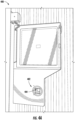
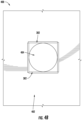
- FIG. 7A and FIG. 7B are example composite images 700A and 700B generated by capturing pictures of a laser scanner lens using an example implementation of the inspection system 300 of the present disclosure.
- intensity levels of the pixels in the images are determined and compared. Pixels that have an intensity above a threshold, determination of which is described above, indicates the presence of the debris as described above.
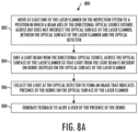
- FIGS. 8A - 8C are flowcharts illustrating various steps in a method 800 of inspecting an optical surface of a laser scanner with an inspection system that includes a directional optical source and an optical detector, according to various example implementations of the present disclosure.
- the method includes moving at least one of the laser scanner or the inspection system to a position in which a beam axis of the directional optical source extends across but does not intersect the optical surface of the laser scanner, between the optical surface of the laser scanner and the optical detector, as shown at block 802 of FIG. 8A .
- the method includes emitting a light beam from the directional optical source, across the optical surface of the laser scanner so that light from the light beam is incident on debris disposed on the optical surface of the laser scanner, as shown at block 804.
- the method includes collecting the light at the optical detector to form an image that indicates presence of the debris on the optical surface of the laser scanner, as shown at block 806.
- the method includes generating feedback to alert a user of the presence of the debris, as shown at block 8
- the directional optical source is positioned on a perimeter of the optical surface of the laser scanner.
- the inspection system includes a housing in which the optical detector is contained.
- the housing defines a housing aperture, and the directional optical source is positioned on a perimeter of the housing aperture.
- the directional optical source includes an optical fiber configured to carry light to a fiber tip at which light beam is emitted at block 804, and the fiber tip is positioned on the perimeter of the housing aperture so that the light beam is emitted across the housing aperture.
- the directional optical source is contained in the housing of the inspection system, and
- the at least one of the laser scanner or the inspection system is moved at block 802 so that the optical surface is positioned over the housing aperture and exposed to the optical detector contained in the housing, and so that the housing aperture is covered by the laser scanner to block ambient light from entering the housing through the housing aperture.
- the inspection system further includes a mount on an outer surface of the housing over the housing aperture.
- the mount defines a mount aperture that overlaps the housing aperture, and the directional optical source is positioned on a perimeter of the mount aperture and thereby the perimeter of the housing aperture.
- the directional optical source includes an optical fiber configured to carry light to a fiber tip at which light beam is emitted at block 804, and the fiber tip is positioned on the perimeter of the mount aperture so that the light beam is emitted across the mount aperture and thereby the housing aperture.
- the at least one of the laser scanner or the inspection system is moved at block 802 so that the optical surface is positioned over the mount aperture and exposed to the optical detector contained in the housing, and so that the mount aperture is covered by the laser scanner to block ambient light from entering the housing through the mount aperture and the housing aperture.
- the inspection system includes a plurality of directional optical sources, and in the position to which the at least one of the laser scanner or the inspection system is moved at block 802, beam axes of respective ones of the plurality of directional optical sources extend across but do not intersect the optical surface of the laser scanner.
- emitting the light beam at block 804 includes emitting light beams from respective ones of the plurality of directional optical sources, across the optical surface of the laser scanner so that light from one or more of the light beams is incident on the debris, as shown at block 810 of FIG. 8B .
- the light beams are emitted at block 810 individually, and the light is collected at block 806 individually for respective ones of the light beams to form respective images one or more of which indicates the presence of the debris on the optical surface of the laser scanner.
- the method 800 further includes creating a composite image from the respective images, as shown at block 812 of FIG. 8C .
- the method also includes processing the composite image to determine pixels in the composite image that have an intensity above a threshold that indicates the presence of the debris, as shown at block 814.
- the optical surface is of a lens through which laser beams are emitted from the laser scanner.
- the optical detector comprises a camera configured to collect the light at block 806 to form the image that indicates the presence of the debris.
- the directional optical source comprises light emitting diodes (LEDs).
- LEDs light emitting diodes
- An inspection system for inspecting an optical surface of a laser scanner comprising: a directional optical source configured to emit a light beam when at least one of the laser scanner or the inspection system are moved to a position in which a beam axis of the directional optical source extends across but does not intersect the optical surface of the laser scanner, between the optical surface of the laser scanner and the optical detector, the directional optical source configured to emit the light beam across the optical surface of the laser scanner so that light from the light beam is incident on debris disposed on the optical surface of the laser scanner; an optical detector configured to collect the light to form an image that indicates presence of the debris on the optical surface of the laser scanner; and a computer configured to generate feedback to alert a user of the presence of the debris.
- Clause 3 The inspection system of clause 1 or clause 2, wherein the inspection system further comprises a housing in which the optical detector is contained, and wherein the housing defines a housing aperture, and the directional optical source is positioned on a perimeter of the housing aperture.
- the directional optical source includes an optical fiber configured to carry light to a fiber tip at which light beam is emitted, and the fiber tip is positioned on the perimeter of the housing aperture so that the light beam is emitted across the housing aperture.
- Clause 5 The inspection system of clause 3 or clause 4, wherein the directional optical source is contained in the housing of the inspection system, and wherein the at least one of the laser scanner or the inspection system is moved so that the optical surface is positioned over the housing aperture and exposed to the optical detector contained in the housing, and so that the housing aperture is covered by the laser scanner to block ambient light from entering the housing through the housing aperture.
- the directional optical source includes an optical fiber configured to carry light to a fiber tip at which light beam is emitted, and the fiber tip is positioned on the perimeter of the mount aperture so that the light beam is emitted across the mount aperture and thereby the housing aperture.
- Clause 8 The inspection system of clause 6 or clause 7, wherein the at least one of the laser scanner or the inspection system is moved so that the optical surface is positioned over the mount aperture and exposed to the optical detector contained in the housing, and so that the mount aperture is covered by the laser scanner to block ambient light from entering the housing through the mount aperture and the housing aperture.
- Clause 9 The inspection system of any of clauses 1 to 8, wherein the inspection system includes a plurality of directional optical sources, and in the position to which the at least one of the laser scanner or the inspection system is moved, beam axes of respective ones of the plurality of directional optical sources extend across but do not intersect the optical surface of the laser scanner, and wherein the directional optical source configured to emit the light beam includes respective ones of the plurality of directional optical sources configured to emit light beams across the optical surface of the laser scanner so that light from one or more of the light beams is incident on the debris.
- Clause 10 The inspection system of clause 9, wherein the light beams are emitted individually, and the light is collected individually for respective ones of the light beams to form respective images one or more of which indicates the presence of the debris on the optical surface of the laser scanner.
- Clause 11 The inspection system of clause 10, wherein the computer is configured to at least: create a composite image from the respective images; process the composite image to determine pixels in the composite image that have an intensity above a threshold that indicates the presence of the debris.
- Clause 12 The inspection system of any of clauses 1 to 11, wherein the optical surface is of a lens through which laser beams are emitted from the laser scanner.
- Clause 13 The inspection system of any of clauses 1 to 12, wherein the optical detector comprises a camera configured to collect the light to form the image that indicates the presence of the debris.
- a method of inspecting an optical surface of a laser scanner with an inspection system that includes a directional optical source and an optical detector comprising: moving at least one of the laser scanner or the inspection system to a position in which a beam axis of the directional optical source extends across but does not intersect the optical surface of the laser scanner, between the optical surface of the laser scanner and the optical detector; emitting a light beam from the directional optical source, across the optical surface of the laser scanner so that light from the light beam is incident on debris disposed on the optical surface of the laser scanner; collecting the light at the optical detector to form an image that indicates presence of the debris on the optical surface of the laser scanner; and generating feedback to alert a user of the presence of the debris.
- Clause 16 The method of clause 15, wherein in the position to which the at least one of the laser scanner or the inspection system is moved, the directional optical source is positioned on a perimeter of the optical surface of the laser scanner.
- Clause 17 The method of clause 15 or clause 16, wherein the inspection system includes a housing in which the optical detector is contained, and wherein the housing defines a housing aperture, and the directional optical source is positioned on a perimeter of the housing aperture.
- the directional optical source includes an optical fiber configured to carry light to a fiber tip at which light beam is emitted, and the fiber tip is positioned on the perimeter of the housing aperture so that the light beam is emitted across the housing aperture.
- Clause 19 The method of clause 17 or clause 18, wherein the directional optical source is contained in the housing of the inspection system, and wherein the at least one of the laser scanner or the inspection system is moved so that the optical surface is positioned over the housing aperture and exposed to the optical detector contained in the housing, and so that the housing aperture is covered by the laser scanner to block ambient light from entering the housing through the housing aperture.
- Clause 20 The method of any of clauses 17 to 19, wherein the inspection system further includes a mount on an outer surface of the housing over the housing aperture, and wherein the mount defines a mount aperture that overlaps the housing aperture, and the directional optical source is positioned on a perimeter of the mount aperture and thereby the perimeter of the housing aperture.
- Clause 21 The method of clause 20, wherein the directional optical source includes an optical fiber configured to carry light to a fiber tip at which light beam is emitted, and the fiber tip is positioned on the perimeter of the mount aperture so that the light beam is emitted across the mount aperture and thereby the housing aperture.
- the directional optical source includes an optical fiber configured to carry light to a fiber tip at which light beam is emitted, and the fiber tip is positioned on the perimeter of the mount aperture so that the light beam is emitted across the mount aperture and thereby the housing aperture.
- Clause 22 The method of clause 20 or clause 21, wherein the at least one of the laser scanner or the inspection system is moved so that the optical surface is positioned over the mount aperture and exposed to the optical detector contained in the housing, and so that the mount aperture is covered by the laser scanner to block ambient light from entering the housing through the mount aperture and the housing aperture.
- Clause 23 The method of any of clauses 15 to 22, wherein the inspection system includes a plurality of directional optical sources, and in the position to which the at least one of the laser scanner or the inspection system is moved, beam axes of respective ones of the plurality of directional optical sources extend across but do not intersect the optical surface of the laser scanner, and wherein emitting the light beam includes emitting light beams from respective ones of the plurality of directional optical sources, across the optical surface of the laser scanner so that light from one or more of the light beams is incident on the debris.
- Clause 24 The method of clause 23, wherein the light beams are emitted individually, and the light is collected individually for respective ones of the light beams to form respective images one or more of which indicates the presence of the debris on the optical surface of the laser scanner.
- Clause 25 The method of clause 24 further comprising: creating a composite image from the respective images; processing the composite image to determine pixels in the composite image that have an intensity above a threshold that indicates the presence of the debris.
- Clause 26 The method of any of clauses 15 to 25, wherein the optical surface is of a lens through which laser beams are emitted from the laser scanner.
- Clause 27 The method of any of clauses 15 to 26, wherein the optical detector comprises a camera configured to collect the light to form the image that indicates the presence of the debris.
Landscapes
- Physics & Mathematics (AREA)
- General Physics & Mathematics (AREA)
- Engineering & Computer Science (AREA)
- Chemical & Material Sciences (AREA)
- Analytical Chemistry (AREA)
- Immunology (AREA)
- General Health & Medical Sciences (AREA)
- Biochemistry (AREA)
- Life Sciences & Earth Sciences (AREA)
- Pathology (AREA)
- Health & Medical Sciences (AREA)
- Optics & Photonics (AREA)
- Plasma & Fusion (AREA)
- Mechanical Engineering (AREA)
- Computer Vision & Pattern Recognition (AREA)
- Signal Processing (AREA)
- Geometry (AREA)
- Investigating Materials By The Use Of Optical Means Adapted For Particular Applications (AREA)
Applications Claiming Priority (1)
| Application Number | Priority Date | Filing Date | Title |
|---|---|---|---|
| US17/653,779 US12025565B2 (en) | 2022-03-07 | 2022-03-07 | Inspection system and methods for inspecting an optical surface of a laser scanner |
Publications (1)
| Publication Number | Publication Date |
|---|---|
| EP4242644A1 true EP4242644A1 (de) | 2023-09-13 |
Family
ID=84367181
Family Applications (1)
| Application Number | Title | Priority Date | Filing Date |
|---|---|---|---|
| EP22209031.8A Pending EP4242644A1 (de) | 2022-03-07 | 2022-11-23 | Inspektionssystem und verfahren zur inspektion einer optischen oberfläche eines laserscanners |
Country Status (3)
| Country | Link |
|---|---|
| US (1) | US12025565B2 (de) |
| EP (1) | EP4242644A1 (de) |
| CN (1) | CN116718610A (de) |
Citations (5)
| Publication number | Priority date | Publication date | Assignee | Title |
|---|---|---|---|---|
| EP1643281A1 (de) * | 2004-10-02 | 2006-04-05 | Trumpf Werkzeugmaschinen GmbH + Co. KG | Optisches Element einer Laserbearbeitungsmaschine und Halterung des optischen Elements |
| KR20070113381A (ko) * | 2006-05-23 | 2007-11-29 | 주식회사 케이씨텍 | 이물질 감지 장치 및 방법 |
| US20140218725A1 (en) * | 2013-02-05 | 2014-08-07 | Shenzhen China Star Optoelectronics Technology Co., Ltd. | Inspecting Device for Detecting Appearance of Debris on a Surface of a Glass Substrate, Inspecting Apparatus and Method for Conducting Inspection |
| DE102014203798A1 (de) * | 2014-03-03 | 2015-09-03 | Volkswagen Aktiengesellschaft | Verfahren zur Überwachung des Verschmutzungs- und/oder Beschädigungszustands an einem Schutzglas eines Laserbearbeitungskopfs und Vorrichtung zur Laserbearbeitung |
| WO2015134291A1 (en) * | 2014-03-06 | 2015-09-11 | Microsoft Technology Licensing, Llc | Object presence and condition detection |
-
2022
- 2022-03-07 US US17/653,779 patent/US12025565B2/en active Active
- 2022-11-23 EP EP22209031.8A patent/EP4242644A1/de active Pending
- 2022-12-02 CN CN202211539899.5A patent/CN116718610A/zh active Pending
Patent Citations (5)
| Publication number | Priority date | Publication date | Assignee | Title |
|---|---|---|---|---|
| EP1643281A1 (de) * | 2004-10-02 | 2006-04-05 | Trumpf Werkzeugmaschinen GmbH + Co. KG | Optisches Element einer Laserbearbeitungsmaschine und Halterung des optischen Elements |
| KR20070113381A (ko) * | 2006-05-23 | 2007-11-29 | 주식회사 케이씨텍 | 이물질 감지 장치 및 방법 |
| US20140218725A1 (en) * | 2013-02-05 | 2014-08-07 | Shenzhen China Star Optoelectronics Technology Co., Ltd. | Inspecting Device for Detecting Appearance of Debris on a Surface of a Glass Substrate, Inspecting Apparatus and Method for Conducting Inspection |
| DE102014203798A1 (de) * | 2014-03-03 | 2015-09-03 | Volkswagen Aktiengesellschaft | Verfahren zur Überwachung des Verschmutzungs- und/oder Beschädigungszustands an einem Schutzglas eines Laserbearbeitungskopfs und Vorrichtung zur Laserbearbeitung |
| WO2015134291A1 (en) * | 2014-03-06 | 2015-09-11 | Microsoft Technology Licensing, Llc | Object presence and condition detection |
Also Published As
| Publication number | Publication date |
|---|---|
| US12025565B2 (en) | 2024-07-02 |
| CN116718610A (zh) | 2023-09-08 |
| US20230280279A1 (en) | 2023-09-07 |
Similar Documents
| Publication | Publication Date | Title |
|---|---|---|
| EP3109622B1 (de) | Automatisches harzgratreduktionssystem | |
| EP2677312B1 (de) | Ultraschalluntersuchungssystem für Kompositstrukturen mit eingeschränktem Zugang | |
| US20170326729A1 (en) | Robot system path planning for asset health management | |
| US11287507B2 (en) | System and method for testing a structure using laser ultrasound | |
| EP2850417B1 (de) | Kontaminationsidentifizierungssystem | |
| US20150302669A1 (en) | Method for inspecting an airborne vehicle | |
| KR20030026972A (ko) | 테스팅의 목적으로 초음파 신호 발생기의 위치를 결정하여배치시키기 위한 시스템 및 방법 | |
| US9404898B1 (en) | Laser ultrasound testing in limited-access areas | |
| CN103163144A (zh) | 用于在喷漆之前监视施加到机动车车身上的底漆层的质量的方法 | |
| KR102858637B1 (ko) | 홀의 광학 이미징 및 스캐닝 | |
| EP4242644A1 (de) | Inspektionssystem und verfahren zur inspektion einer optischen oberfläche eines laserscanners | |
| CN117245228B (zh) | 工件识别及柔性加工装置、方法 | |
| CN115958640A (zh) | 用于进行准确拾放的打印式基准系统 | |
| US10539538B2 (en) | Laser ultrasound system and method for inspection of a contoured structure | |
| CN221506716U (zh) | 一种光学封装元件的缺陷检测装置 | |
| US20240070837A1 (en) | Natural feature pick and place system for composite materials | |
| CN115562298A (zh) | 一种机器人检测用围栏防护系统和方法 | |
| Schmutzler et al. | Automated Scarfing: A Prerequisite for Future Structural CFC Repairs | |
| EP4563296A1 (de) | Verfahren zum betrieb einer layup-zelle während der verbundstoffherstellung und zugehörige layup-zellen | |
| CA3182625A1 (en) | Method and apparatus for inspecting a composite assembly | |
| CN119596970A (zh) | 一种基于前端实时缺陷识别的无人机自主巡检系统 | |
| IL313563A (en) | System and method for detecting faults in a safety coupling | |
| CN121979278A (en) | Unmanned aerial vehicle autonomous inspection and live working cooperation method and system | |
| CN116721146A (zh) | 基于点云数据的机体凹坑检测设备及检测方法 | |
| AU2007200013A1 (en) | System and method for locating and positioning an ultrasonic signal generator for testing purposes |
Legal Events
| Date | Code | Title | Description |
|---|---|---|---|
| PUAI | Public reference made under article 153(3) epc to a published international application that has entered the european phase |
Free format text: ORIGINAL CODE: 0009012 |
|
| STAA | Information on the status of an ep patent application or granted ep patent |
Free format text: STATUS: THE APPLICATION HAS BEEN PUBLISHED |
|
| AK | Designated contracting states |
Kind code of ref document: A1 Designated state(s): AL AT BE BG CH CY CZ DE DK EE ES FI FR GB GR HR HU IE IS IT LI LT LU LV MC ME MK MT NL NO PL PT RO RS SE SI SK SM TR |
|
| STAA | Information on the status of an ep patent application or granted ep patent |
Free format text: STATUS: REQUEST FOR EXAMINATION WAS MADE |
|
| 17P | Request for examination filed |
Effective date: 20240311 |
|
| RBV | Designated contracting states (corrected) |
Designated state(s): AL AT BE BG CH CY CZ DE DK EE ES FI FR GB GR HR HU IE IS IT LI LT LU LV MC ME MK MT NL NO PL PT RO RS SE SI SK SM TR |
|
| GRAP | Despatch of communication of intention to grant a patent |
Free format text: ORIGINAL CODE: EPIDOSNIGR1 |
|
| STAA | Information on the status of an ep patent application or granted ep patent |
Free format text: STATUS: GRANT OF PATENT IS INTENDED |
|
| INTG | Intention to grant announced |
Effective date: 20260113 |
|
| GRAJ | Information related to disapproval of communication of intention to grant by the applicant or resumption of examination proceedings by the epo deleted |
Free format text: ORIGINAL CODE: EPIDOSDIGR1 |
|
| STAA | Information on the status of an ep patent application or granted ep patent |
Free format text: STATUS: REQUEST FOR EXAMINATION WAS MADE |
|
| GRAP | Despatch of communication of intention to grant a patent |
Free format text: ORIGINAL CODE: EPIDOSNIGR1 |
|
| STAA | Information on the status of an ep patent application or granted ep patent |
Free format text: STATUS: GRANT OF PATENT IS INTENDED |
|
| INTC | Intention to grant announced (deleted) | ||
| INTG | Intention to grant announced |
Effective date: 20260327 |