EP4242860B1 - Dispositif de décodage de communication de données selon une norme de bus série universel - Google Patents
Dispositif de décodage de communication de données selon une norme de bus série universel Download PDFInfo
- Publication number
- EP4242860B1 EP4242860B1 EP23160209.5A EP23160209A EP4242860B1 EP 4242860 B1 EP4242860 B1 EP 4242860B1 EP 23160209 A EP23160209 A EP 23160209A EP 4242860 B1 EP4242860 B1 EP 4242860B1
- Authority
- EP
- European Patent Office
- Prior art keywords
- data
- clock
- usb
- bit
- stuffed
- Prior art date
- Legal status (The legal status is an assumption and is not a legal conclusion. Google has not performed a legal analysis and makes no representation as to the accuracy of the status listed.)
- Active
Links
Images


Classifications
-
- H—ELECTRICITY
- H04—ELECTRIC COMMUNICATION TECHNIQUE
- H04L—TRANSMISSION OF DIGITAL INFORMATION, e.g. TELEGRAPHIC COMMUNICATION
- H04L1/00—Arrangements for detecting or preventing errors in the information received
- H04L1/004—Arrangements for detecting or preventing errors in the information received by using forward error control
- H04L1/0045—Arrangements at the receiver end
- H04L1/0047—Decoding adapted to other signal detection operation
-
- G—PHYSICS
- G06—COMPUTING OR CALCULATING; COUNTING
- G06F—ELECTRIC DIGITAL DATA PROCESSING
- G06F13/00—Interconnection of, or transfer of information or other signals between, memories, input/output devices or central processing units
- G06F13/38—Information transfer, e.g. on bus
- G06F13/42—Bus transfer protocol, e.g. handshake; Synchronisation
- G06F13/4282—Bus transfer protocol, e.g. handshake; Synchronisation on a serial bus, e.g. I2C bus, SPI bus
- G06F13/4291—Bus transfer protocol, e.g. handshake; Synchronisation on a serial bus, e.g. I2C bus, SPI bus using a clocked protocol
-
- G—PHYSICS
- G06—COMPUTING OR CALCULATING; COUNTING
- G06F—ELECTRIC DIGITAL DATA PROCESSING
- G06F1/00—Details not covered by groups G06F3/00 - G06F13/00 and G06F21/00
- G06F1/04—Generating or distributing clock signals or signals derived directly therefrom
- G06F1/14—Time supervision arrangements, e.g. real time clock
-
- G—PHYSICS
- G06—COMPUTING OR CALCULATING; COUNTING
- G06F—ELECTRIC DIGITAL DATA PROCESSING
- G06F13/00—Interconnection of, or transfer of information or other signals between, memories, input/output devices or central processing units
- G06F13/38—Information transfer, e.g. on bus
- G06F13/382—Information transfer, e.g. on bus using universal interface adapter
-
- G—PHYSICS
- G06—COMPUTING OR CALCULATING; COUNTING
- G06F—ELECTRIC DIGITAL DATA PROCESSING
- G06F13/00—Interconnection of, or transfer of information or other signals between, memories, input/output devices or central processing units
- G06F13/38—Information transfer, e.g. on bus
- G06F13/40—Bus structure
- G06F13/4063—Device-to-bus coupling
- G06F13/4068—Electrical coupling
-
- G—PHYSICS
- G06—COMPUTING OR CALCULATING; COUNTING
- G06F—ELECTRIC DIGITAL DATA PROCESSING
- G06F13/00—Interconnection of, or transfer of information or other signals between, memories, input/output devices or central processing units
- G06F13/38—Information transfer, e.g. on bus
- G06F13/42—Bus transfer protocol, e.g. handshake; Synchronisation
- G06F13/4282—Bus transfer protocol, e.g. handshake; Synchronisation on a serial bus, e.g. I2C bus, SPI bus
-
- H—ELECTRICITY
- H04—ELECTRIC COMMUNICATION TECHNIQUE
- H04L—TRANSMISSION OF DIGITAL INFORMATION, e.g. TELEGRAPHIC COMMUNICATION
- H04L7/00—Arrangements for synchronising receiver with transmitter
- H04L7/0079—Receiver details
-
- H—ELECTRICITY
- H04—ELECTRIC COMMUNICATION TECHNIQUE
- H04L—TRANSMISSION OF DIGITAL INFORMATION, e.g. TELEGRAPHIC COMMUNICATION
- H04L7/00—Arrangements for synchronising receiver with transmitter
- H04L7/0079—Receiver details
- H04L7/0087—Preprocessing of received signal for synchronisation, e.g. by code conversion, pulse generation or edge detection
Definitions
- the present application is generally directed to communication system, and more particularly to a device for decoding the data communication under universal serial bus standard.
- USB Universal Serial Bus
- USB device USB device/function device
- USB is a serial interface standard which allows communications between a host device and various USB-compliant devices to be performed via a common bus line.
- USB 1.X defines two modes having different data transfer rates, i.e. low-speed mode (LS) of 1.5 Mbps and full-speed mode (FS) of 12 Mbps.
- LS low-speed mode
- FS full-speed mode
- the LS and FS mode may also be used in the standard termed USB 2.0, USB 3.0, etc.
- one USB host device can be connected with up to 127 devices via a common bus line which includes USB data lines and power supply lines.
- a field programmable gate array (FPGA) or a microcontroller/microprocessor may be used to complete USB clock synchronization and USB signal analysis.
- US2003/018839 A1 , US2010/275037 A1 and XP011375064 disclose USB data receiver performing NRZI decoding before bit unstuffing implemented on programmable hardware logic like ASICs or FPGAs or using state machines.
- a device adapted to implement a state machine which defines a plurality of predetermined states and a plurality of predetermined events, for decoding USB data communicated over a universal serial bus (USB), the device comprising:
- a clock rate of the device clock is at least 6 times the data transferring rate over the USB.
- a clock rate of the device clock is no more than 12 times of the data transferring rate over the USB.
- the device further comprises an indicator output terminal configured to output an indication signal indicative that the bus state of the USB is an end of package or not.
- control circuity further comprises a counter unit (312) including first and second counters that are configurable to operate as a unified 32-bit counter or as two separate 16-bit counters.
- control circuity further comprises a control logic circuitry connected to the counter unit to provide control signals for the counters of the counter unit, wherein the control logic circuitry is also connected to the event generator to receive event signals therefrom, and wherein the control logic circuit is configured to use the control signals to reset the counter after an event is triggered by the event generator.
- control circuity further comprises a match register configured to load expected match value.
- control circuity further comprises a match logic module configured to generate a match logic in response to the count values from the counter unit being equals to the match values from the match register, and wherein the one of the predetermined events is triggered only when the match logic is generated.
- the device further comprises an interrupt module connected to the event generator, wherein the interrupt module is configured to generate an interrupt signal in response to receiving a predetermined one of the event signals from the event generator.
- USB does not transmit data directly on the USB data lines. It converts the data into NRZI encoded data with Not-Return-to-Zero-Inverse (NRZI) encoding, and then the NRZI encoded data are transmitted on the USB data lines. Data capture by using a conventional low cost microcontroller may therefore be challenging.
- the NRZI data comprises J state and K state.
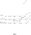
- FIG. 1 illustrates an example of a data encoding for USB transmission, using bit-stuffing and subsequent NRZI encoding.
- NRZI encoding a "1" is represented by no change in level and a "0” is represented by a change in level.
- a string of "0” thus causes the NRZI data to toggle each bit time.
- “1”s may also be referred to as “one”s.”
- 0"s may also be referred to as "zero"s.
- a "0" is inserted after every six consecutive "1", in the raw data, as shown by the middle waveform, at 102. This process is known as “bit stuffing” and the inserted "0” is known as a "stuffed-bit”.
- the stuffed data packet is then converted to NRZI, with each "0” causing a data transition, and each "1” causing no transition, as shown by the lower waveform, at 103.
- One difficulty in decoding the data on the USB data lines is how to detect the stuffed-bit.
- FIG. 2 is a schematic block diagram of a system 200 for decoding the data communication under universal serial bus (USB) standard.
- System 200 may comprise a USB host 202, a USB device 204 (also sometimes referred to as a "USB function", or “USB peripheral device”), USB data lines 206, a device 208, a USB transceiver 210, a co-processor 212, and a SPI interface 214.
- the USB device 204 may be coupled to the USB host 202 through USB cables.
- the USB includes two data lines D+/D- that carry data and two lines VBUS/GND that carry power.
- the supply voltage on the line VBUS may be +5V.
- the USB device 204 is configured to communicate data with the USB host 202 over data lines 206.
- the USB device 204 may receive data from the USB host 202.
- the USB device 204 may transmit data to the USB host 202 based on the request of the USB host 202.
- the system 200 uses bit stuffing and NRZI encoding system (not shown) in physical layer of the USB host 202 to encode the data for USB transmission.
- the system 200 may be used for LS and FS mode which may be used in the standard of USB 1.x, 2.0, 3.0 etc.
- the device 208 may be coupled to one of the USB host 202 and the USB device 204. In some embodiments, the device 208 may be on the host side and coupled to the USB host 202 through cables. In some embodiments, the device 208 may be on the function side and coupled to the USB device 204 through cables. In some other embodiments, the device 208 may be located separately from the host side and the function side and coupled to one of the USB host 202 and the USB device 204 through cables.
- the device 208 may be a peripheral which is adapted to implement a state machine with one 32 bit counter. In some embodiments, the device 208 is adapted to implement a state machine with two 16 bit counters. Each of the 16 bit counters may be used for some parts of the state machine.
- the state machine defines a plurality of predetermined states and a plurality of predetermined events, for decoding USB data communicated over a universal serial bus (USB).
- the device 208 is configured to receive the data over the USB data lines 206 and then synchronize the data, provide decoded stuffed-bit stripped synchronized data by using the predetermined states and events.
- the device 208 comprises pair of data input terminals 218, 228 for receiving the USB encoded data with bit stuffing which is encoded from the raw data. Then the device 208 synchronizes the data and processes the synchronized data based on the predetermined events and states.
- the device 208 also comprises a clock input terminal (not shown) for receiving a system clock from a clock source. Then the device 208 identifies the stuffed-bits and decode synchronized data to raw data "1" and raw data "0".
- Some of the predetermined events comprise identifying a stuffed-bit in the synchronized data. Some of the predetermined events comprise stripping the identified stuffed-bit from synchronized data and not toggling output clock, to provide stuff-bit stripped synchronized data.
- a combination of the predetermined events comprises decoding the stuffed-bit stripped synchronized data, to provide decoded stuffed-bit stripped synchronized data, and a further of the predetermined events comprises outputting decoded stuffed-bit stripped synchronized data and toggling the output clock at the output terminals.
- the USB data lines 206 include two data lines D+/D- that carry the encoded data.
- the synchronized data from each of the data lines D+ and D- have high level and low level. And there are rising edges from the low level to the high level and falling edges from the high level to the low level.
- the device 208 checks if the USB bus state is "end of package” (EOP) which means the synchronized data are not valid. If the USB bus state is not EOP, the synchronized data "1" means the state of the data on one of the data lines D+ and D- does not change, and the synchronized data "0" means the state of the data on the data lines D+ and D- changes.
- EOP end of package
- the device 208 may use one of the data lines D+ and D- to decode the synchronized data.
- the device 208 decodes the synchronized data "1" when the data on the data line D- and data line D+ does not have a rising edge or a falling edge.
- the device 208 decodes the synchronized data "0" when the data on the data lines D+ D- has one of the rising edge and the falling edge.
- the device 208 identifies a stuffed-bit when the synchronized data "0" is received after six synchronized data "1" received consecutively.
- the stuffed-bit will not be output by the device 208 and the output clock will not be toggled.
- the device 208 outputs the decoded stuffed-bit stripped synchronized data when the output clock is toggled.
- the details of the device 208 will be described below in combination of FIG. 3 .
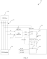
- FIG. 3 shows, at block level, an embodiment of the device 208 adapted to implement a state machine which defines a plurality of predetermined states and a plurality of predetermined events, for decoding USB data communicated over a universal serial bus (USB).
- the device 300 comprises a pair of data input terminals and a clock input terminal, a clock processor 302, an event generator 304, a state logic circuitry 306, output terminals 308, interrupts module 310, counter unit 312, prescaler 314, match register 316, match logic module 318 and control logic circuitry 320.
- the counter unit 312, prescaler 314, match register 316, match logic module 318 and control logic circuitry 320 are included in a control circuity 322 which is coupled to the event generator 304 and configured to provide control information to the event generator 304.
- control circuity 322 which is coupled to the event generator 304 and configured to provide control information to the event generator 304.
- the pair of data input terminals are used for receiving the USB data
- the clock input terminal is used for receiving a system clock.
- the clock processor 302 is coupled to the pair of data input terminals and the clock input terminal, and is configured to output synchronized data for the event generator 304 and a device clock (SCT clock) based on the system clock for various components of the device 300.
- the device also outputs a prescaler clock for the prescaler 314.
- the system clock may be generated by a clock generator.
- the device clock and the prescaler clock are equivalent to the system clock.
- one or both of the device clock and the prescaler clock may be differ from the system clock with respect to clock rate.
- the clock rate is also referred to as the clock frequency .
- the data transferring rate over the USB is typically 12Mbps.
- the clock rate of the device clock is no more than 12 times of the data transferring rate over the USB.
- the clock rate of the device clock may be one of 72MHz, 96MHz, 120MHz and 144MHz.
- the clock rate of the system clock of device 300 may be 6times, 8times, 10times or 12 times of the data transferring rate. By this way, the device 300 may have enough time to decode the data package on the USB.
- the prescaler 314 is configured to produce one or more clock signals for the counter unit 312 using the prescaler clock from the clock processor 302.
- the control logic circuitry 320 is configured to produce control signals to control at least one counter of the counter unit 312. The control signals determine when the counter is incremented, cleared and loaded.
- the control logic circuitry 320 includes an input to receive event signals generated by the event generator 304.
- the control logic circuitry is configured to provide corresponding control signals to the counter unit 312 in response to different event signals, i.e., when certain events are triggered.
- the control logic circuit 322 is configured to use the control signals to reset the counters of the counter unit 312 after an event is triggered by the event generator 304.
- the match register 316 is configured to load expected match value.
- the expected match value may be thirteen when the clock rate of the system clock of device 300 is 12 times of the data transferring rate, which means the USB data may be received at the time of the thirteenth clock cycle comes.
- the match logic module 318 is configured to generate a match logic in response to the count values from the counter unit 312 being equal to the expected match values from the match register, and wherein the one of the predetermined events is triggered only when the match logic is generated.
- each data from the USB could be captured for every twelve counts when the clock rate of the system clock of device 300 is twelve times of the data transferring rate.
- Another of the predetermined events comprises stripping the identified stuffed-bit from the synchronized data and not toggling output clock, to provide stuff-bit stripped synchronized data, such as data "1" and data "0".
- a combination of the predetermined events comprises decoding the stuffed-bit stripped synchronized data, to provide decoded stuffed-bit stripped synchronized data.
- a further of the predetermined events comprises outputting, at the output terminals, the decoded stuffed-bit stripped synchronized data and toggling the output clock.
- the output terminals 308 are configured to output an indication signal indicative whether the bus state of the USB is an end of package (EOP) or not.
- EOP end of package
- an interrupt module 310 is configured to generate an interrupt signal in response to receiving a predetermined one of the event signals from the event generator.
- present application uses a device adapted to implement a state machine with predetermined states and events to decode the data communication on the USB bus.
- the device may be implemented with a low cost MCU which may reduce the cost and may be easily integrated into other embedded products such as a secure bus monitor.
- an apparatus 216 is used for decoding USB data communicated over the USB data lines.
- the apparatus 216 comprises the device 208 which is also shown as the device 300 in FIG. 3 .
- the apparatus may also comprise a co-processor 212 and a serial peripheral interface (SPI) interface 214.
- SPI serial peripheral interface
- the co-processor 212 comprises input terminals 220, 222, and 224 and at least one output 226 terminal.
- the input terminals 220, 222 of the co-processor 212 are coupled to the output terminals of the device 208 and configured to receive the output clock (at input terminal 220) and the decoded stuffed-bit stripped synchronized data (at input terminal 224) from the device 208.
- the co-processor 212 is configured to convert the decoded stuffed-bit stripped synchronized data and output clock into serial peripheral interface (SPI) signals.
- the device 208 also outputs an indication signal as shown by SCT_CS to the input 222 of the co-processor 212.
- the indication signal SCT_CS is used for indicating whether the bus state of the USB is an end of package (EOP) or not. Then the co-processor 212 is configured to convert the indication signal to a SPI indication signal as shown as SPI_CS.
- the co-processor 212 may transmit the SPI signals to the SPI interface 214 by internal bus. In embodiments which are implemented on or together with an ARM Cortex M architecture, the internal bus may include AHB bus and APB bridge. In some other embodiments, the co-processor 212 may convert the raw data signals in other ways to meet different requirement.
- the serial peripheral interface (SPI) interface 214 is coupled to the output terminals 216 of the processor.
- the apparatus 216 may be configured to output the SPI indication signal (SPI_CS), SPI data signal (SPI_MOSI) and SPI clock signal (SPI_CLK) via the SPI interface 214.
- a USB transceiver 210 is coupled between the USB host 202 and the device 208 for improving the signal quality and signal integrity.
- the USB data lines D+ and D- carry analog data.
- the transceiver 210 is used to transfer the analog data to digital data.
- the device 208 may also receive the data from data lines directly without the transceiver 210 because the analog data from the data lines are similar to digital data.
- the USB transceiver 210 may be implemented using a transceiver which is well-known in the art.
- a non-transitory computer-readable medium stores a program to execute processing for decoding USB data.
- the USB data is communicated over a universal serial bus (USB) and input to a pair of data input terminals, and a system clock is put to the clock input terminal.
- USB universal serial bus
- the processing comprises generating synchronized data and a device clock based on a system clock by a clock processor 302; providing the synchronized data to an event generator 304; providing control information to the event generator, wherein the control information is generated by a control circuity 322; providing a present state stored by a state logic circuitry 306 to the event generator; providing a plurality of predetermined events to a plurality of registers of the event generator; triggering respective ones of the predetermined events is in response to respective combinations of values of the synchronized data, the device clock, the control information and the present state.
- a one of the predetermined events comprises identifying a stuffed-bit in the synchronized data, another of the predetermined events comprises stripping the identified stuffed-bit from the synchronized data and not toggling output clock, a combination of the predetermined events comprises decoding stuffed-bit stripped synchronized data, and a further of the predetermined events comprises outputting, at the output terminals, decoded stuffed-bit stripped synchronized data and toggling the output clock.
- a clock rate of the device clock is no more than 12 times of the data transferring rate over the USB.
- the processing provides control information to the event generator includes at least one of selecting a rising edge of the synchronized data as an ingredient of the event, and selecting a falling edge of the synchronized data as an ingredient of the event.
- the processing provides control information includes generating count values at counters; loading match values to match registers; and comparing the count values from the counters with the values stored in the match registers to produce a match result.
- the processing generates count values includes generating two counter values that represent a unified 32-bit count values or two separate 16-bit count values.
- the processing further comprises generating an interrupt signal in response to a predetermined event signal from the event generator.
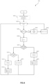
- FIG. 4 illustrates a flow chart 400 of the operation of a device 208 adapted to implement a state machine in accordance with an embodiment of the present application.
- the device 208 receives the data on the USB data lines and processes the data by using predetermined states and events of the state machine.
- the device 208 processes the data may comprise: handling bus state; checking the data on any of the USB data lines; detecting stuffed-bit, raw data 1 and raw data 0.
- the device 208 may output indication signals, raw data signals and clock signals.
- the device 208 may output data 1 when the data on the data line D- or D+ does not have rising edge or falling edge.
- the device may check if the data is a stuffed-bit when the data on the data line D- or D+ has a rising edge or a falling edge, and the device outputs data 0 if the data is not a stuffed-bit, or the device ignores the stuffed-bit if the stuffed-bit is detected.
- the operation of device 208 decode the data with NRZI encoding may include the following steps.
- S401 is a step for initializing output signals of the device 208.
- the indication signal SCT_CS is set to zero.
- Both of the clock signal SCT_CLOCK and the raw data signal SCT_DATA are set to one.
- S402 is a step for detecting or decoding the data received on the USB data lines D+ and D-. If a data packet has been supplied to the device, the operation goes to S403.
- S403 is a step for handling the bus state. If the bus state of the data signal lines is on an "SE0" state which means both of the data signal line D+ and the data signal line D- are at low level and the bus state of the USB is an end of package (EOP), then goes to S404. If the bus state is not an EOP, the operation goes to S406.
- S404 is a step for processing the end of packet (EOP). After processing the EOP, goes to S405.
- S405 is a step for setting the indication signal output by device 208 to zero. The operation returns to S402.
- S406 is a step for processing data on the USB data lines. And the operation goes to S407.
- S407 is a step for checking whether USB D- has rising or falling edge. If the USB D-does not have rising or falling edge, the operation goes to S408. If the USB D- has rising or falling edge, the operation goes to S410. In some embodiments, the step S407 may also be used for judging whether USB D+ has rising or falling edge.
- S408 is a step for telling the data on the USB data lines is not changed and the raw data is one. The operation goes to S409.
- S409 is a step for setting the raw data signal SCT_DATA to one, toggling the clock signal SCT_CLOCK and setting the indication signal SCT_CS to one.
- S410 is a step for checking whether a bit stuffing is inserted or not. If six ones have been received consecutively, the next data zero will be treated as a stuffed-bit and the operation goes to S411. Otherwise, the operation goes to S412.
- S411 is a step for ignoring the stuffed-bit. And the operation returns to S402.
- S412 is a step for telling the data zero received as the raw data zero. The operation goes to S413.
- S413 is for setting the raw data signal SCT_DATA to zero, toggling the clock signal SCT_CLOCK and setting the indication signal SCT_CS to one. And the operation returns to S402.
- the device 208 operates in this manner, making it possible to decoding the data with NRZI encoding on the USB and detecting the stuffed-bit and realizing clock synchronization.
- the device 208 may be adapted to implement a low state machine (“L State Machine”) part and a high state machine (“H State Machine”) part. Both the low state machine and the high state machine are implemented with hardware.
- FIG. 5A and FIG. 5B illustrate a low state machine part and FIG. 6 illustrates a high state machine part respectively in accordance with an embodiment of the present application.
- the state machine may only comprise one part to decode the data and detect the stuffed-bit. It might not be split into a high state machine part and a low state machine part.
- the clock source of state machine may be at 144MHz and the USB data communication may be under full speed mode with the data transferring rate over the USB of 12Mbps.
- the low state machine part may include first counter ("L counter") and the high state machine part may include second counter ("H counter").
- the first counter may be known as using the first half bits of a 32-bit counter.
- the higher counter may be known as using the second half bits of the 32-bit counter.
- Some of the predetermined events comprises stripping the identified stuffed-bit from the synchronized data and not toggling output clock, to provide stuff-bit stripped synchronized data.
- event 0 502, event1, 504, event 3 508, event 4 510, event 5 512, event 7 516 etc. are used to decode data "0" when the data on the data line D- has one of the rising edge and falling edge.
- event 9 520 is used to decode data "1" when no rising edge or falling edge is detected.
- Some of the predetermined events comprises identifying a stuffed-bit in the synchronized data, such as event 10 522 and event 11 524.
- the state logic circuitry 306 in FIG. 3 is configured to store a present state, being a one of the predetermined states.
- the predetermined states comprise state 0 532, state 1 534, state 2 536, state 3 538, state 4 540, state 5, 542, state 6, 544, state 10 552, state 11 554 as shown in FIG. 5A , FIG. 5B and FIG. 6 .
- the event generator 304 in FIG. 3 is configured to trigger respective ones of the predetermined events, in response to respective combinations of values of the synchronized data, the device clock, the control information and the present state.
- a combination of the predetermined events comprises decoding the stuffed-bit stripped synchronized data, to provide decoded stuffed-bit stripped synchronized data.
- a further of the predetermined events comprises outputting, at the output terminals, the decoded stuffed-bit stripped synchronized data and toggling the output clock.
- event 12 526, event 13 528, event 14 530 and event 15 556 are used to detect the end of the package ("EOP").
- the device 208 is configurated to comprise two state machine parts (L State Machine part and High State Machine part) to process the USB signal with predetermined states and events.
- the Low state machine part is for processing USB data streams.
- the high state machine part is for detecting USB EOP.
- the "H State Machine” part may be used for processing USB data streams.
- the “L State Machine” part may be used for detecting USB EOP.
- FIG. 7 illustrates the signals captured by using a logic analyzer.
- the waveform 701 shows the synchronized data carried by the data line D+ and the waveform 702 shows the synchronized data carried by the data line D-.
- the line 703 shows the SPI indication signal (HSPI_CS) output through the SPI interface.
- the waveforms 704 and 705 show the clock signal (HSPI CLK) and the stuffed-bit stripped synchronized data (HSPI_MOSI) output through the SPI interface respectively.
- the device 208 of FIG. 2 receives a synchronized data "E6" from the data line D+ as shown at 701 and the data line D- as shown at 702, the device 208 outputs the decoded stuffed-bit stripped synchronized data and toggling the output clock at the output terminals.
- the co-processor 212 received the decoded stuffed-bit stripped synchronized data, the output clock and the indication signal output from the device 208 and converts them to corresponding signals compliant with the SPI specification.
- the stuffed-bit stripped synchronized data "E6" output through the SPI interface as shown at 705 are captured when the clock signal (HSPI CLK) output through the SPI interface toggles. In this way, the present application may convert complex USB synchronized data into simple SPI signals.
Landscapes
- Engineering & Computer Science (AREA)
- Theoretical Computer Science (AREA)
- General Engineering & Computer Science (AREA)
- Physics & Mathematics (AREA)
- General Physics & Mathematics (AREA)
- Computer Networks & Wireless Communication (AREA)
- Signal Processing (AREA)
- Computer Hardware Design (AREA)
- Information Transfer Systems (AREA)
Claims (9)
- Dispositif adapté pour implémenter un automate fini qui définit une pluralité d'états prédéterminés et une pluralité d'événements prédéterminés, afin de décoder des données USB communiquées sur un bus série universel (USB), le dispositif comprenant :une paire de bornes d'entrée de données destinées à recevoir les données USB, et une borne d'entrée d'horloge destinée à recevoir une horloge système ;un processeur d'horloge (302) couplé à la paire de bornes d'entrée de données et à la borne d'entrée d'horloge, et configuré pour délivrer, en fonction de l'horloge système, des données synchronisées et une horloge de dispositif ;un générateur d'événements (304) couplé au processeur d'horloge pour recevoir les données synchronisées et l'horloge de dispositif ;des circuits logiques d'état (306) couplés à une sortie du générateur d'événements ;des bornes de sortie (308), couplées au générateur d'événements et comprenant une borne de sortie de données décodées et une borne de sortie d'horloge ; etdes circuits de commande (322) couplés au générateur d'événements et destinés à fournir des informations de commande au générateur d'événements ;dans lequel les circuits logiques d'état (306) sont configurés pour stocker un état actuel, celui-ci étant l'un des états prédéterminés ;dans lequel le générateur d'événements est configuré pour déclencher des événements respectifs des événements prédéterminés, en réponse à des combinaisons respectives de valeurs des données synchronisées, de l'horloge de dispositif, des informations de commande et de l'état actuel ;dans lequel :l'un des événements prédéterminés comprend l'identification d'un bit de remplissage dans les données synchronisées,un autre des événements prédéterminés comprend l'extraction du bit de remplissage identifié des données synchronisées et le non-basculement de l'horloge de sortie, afin de fournir des données synchronisées dépourvues de bit de remplissage,une combinaison des événements prédéterminés comprend le décodage des données synchronisées dépourvues de bit de remplissage, pour fournir des données synchronisées dépourvues de bit de remplissage décodées,et encore un autre des événements prédéterminés comprend la délivrance, au niveau des bornes de sortie, des données synchronisées dépourvues de bit de remplissage décodées et le basculement de l'horloge de sortie.
- Dispositif selon la revendication 1, dans lequel une cadence d'horloge de l'horloge SCT est au moins 6 fois le débit de transfert de données sur l'USB.
- Dispositif selon n'importe quelle revendication précédente, dans lequel une cadence d'horloge de l'horloge SCT n'est pas plus de 12 fois le débit de transfert de données sur l'USB.
- Dispositif selon n'importe quelle revendication précédente, comprenant en outre une borne de sortie d'indicateur configurée pour délivrer un signal d'indication indiquant que l'état de bus de l'USB est une fin de paquets (EOP) ou non.
- Dispositif selon n'importe quelle revendication précédente, dans lequel les circuits de commande (322) comprennent en outre une unité de compteur (312) comportant des premier et second compteurs qui sont configurables pour fonctionner en tant que compteur de 32 bits unifié ou en tant que deux compteurs de 16 bits séparés.
- Dispositif selon la revendication 5, dans lequel les circuits de commande (322) comprennent en outre des circuits logiques de commande (320) connectés à l'unité de compteur pour fournir des signaux de commande aux compteurs de l'unité de compteur (312), dans lequel les circuits logiques de commande (320) sont également connectés au générateur d'événements (304) pour recevoir de celui-ci des signaux d'événements, et dans lequel le circuit logique de commande est configuré pour utiliser les signaux de commande afin de réinitialiser le compteur après le déclenchement d'un événement par le générateur d'événements (304).
- Dispositif selon la revendication 5 ou 6, dans lequel les circuits de commande (322) comprennent en outre un registre de concordance (316) configuré pour charger une valeur de concordance attendue.
- Dispositif selon l'une quelconque des revendications 5 à 7, dans lequel les circuits de commande (322) comprennent en outre un module logique de concordance (318) configuré pour générer une logique de concordance lorsque les valeurs de compte provenant de l'unité de compteur sont égales aux valeurs de concordance provenant du registre de concordance, et dans lequel l'un des événements prédéterminés est déclenché uniquement lorsque la logique de concordance est générée.
- Dispositif selon n'importe quelle revendication précédente, comprenant en outre un module d'interruption (310) connecté au générateur d'événements (304), dans lequel le module d'interruption (310) est configuré pour générer un signal d'interruption en réponse à la réception d'un signal prédéterminé des signaux d'événements provenant du générateur d'événements.
Applications Claiming Priority (1)
| Application Number | Priority Date | Filing Date | Title |
|---|---|---|---|
| CN202210252656.7A CN116781207A (zh) | 2022-03-10 | 2022-03-10 | 一种通用串行总线标准下的数据通信解码设备 |
Publications (2)
| Publication Number | Publication Date |
|---|---|
| EP4242860A1 EP4242860A1 (fr) | 2023-09-13 |
| EP4242860B1 true EP4242860B1 (fr) | 2024-12-25 |
Family
ID=85505595
Family Applications (1)
| Application Number | Title | Priority Date | Filing Date |
|---|---|---|---|
| EP23160209.5A Active EP4242860B1 (fr) | 2022-03-10 | 2023-03-06 | Dispositif de décodage de communication de données selon une norme de bus série universel |
Country Status (3)
| Country | Link |
|---|---|
| US (1) | US20230289320A1 (fr) |
| EP (1) | EP4242860B1 (fr) |
| CN (1) | CN116781207A (fr) |
Citations (1)
| Publication number | Priority date | Publication date | Assignee | Title |
|---|---|---|---|---|
| US20100275037A1 (en) * | 2004-03-17 | 2010-10-28 | Super Talent Electronics Inc. | Low-Power USB SuperSpeed Device with 8-bit Payload and 9-bit Frame NRZI Encoding for Replacing 8/10-bit Encoding |
Family Cites Families (1)
| Publication number | Priority date | Publication date | Assignee | Title |
|---|---|---|---|---|
| JP3603732B2 (ja) * | 2000-03-16 | 2004-12-22 | セイコーエプソン株式会社 | データ転送制御装置及び電子機器 |
-
2022
- 2022-03-10 CN CN202210252656.7A patent/CN116781207A/zh active Pending
-
2023
- 2023-03-01 US US18/176,821 patent/US20230289320A1/en not_active Abandoned
- 2023-03-06 EP EP23160209.5A patent/EP4242860B1/fr active Active
Patent Citations (1)
| Publication number | Priority date | Publication date | Assignee | Title |
|---|---|---|---|---|
| US20100275037A1 (en) * | 2004-03-17 | 2010-10-28 | Super Talent Electronics Inc. | Low-Power USB SuperSpeed Device with 8-bit Payload and 9-bit Frame NRZI Encoding for Replacing 8/10-bit Encoding |
Also Published As
| Publication number | Publication date |
|---|---|
| EP4242860A1 (fr) | 2023-09-13 |
| US20230289320A1 (en) | 2023-09-14 |
| CN116781207A (zh) | 2023-09-19 |
Similar Documents
| Publication | Publication Date | Title |
|---|---|---|
| US10055376B1 (en) | Serial peripheral interface system with slave expander | |
| KR970007764B1 (ko) | 프로그램 제어장치 | |
| CN104809094B (zh) | Spi控制器及其通信方法 | |
| CN106569416B (zh) | 一种微控制器的串行接口与仿真调试接口复用方法及装置 | |
| CN107273329B (zh) | 虚拟gpio | |
| US9880965B2 (en) | Variable frame length virtual GPIO with a modified UART interface | |
| CN112559426A (zh) | 数据传输方法、接口电路以及装置 | |
| CA2111264A1 (fr) | Systeme et methode de transfert de donnees vers un peripherique | |
| KR20160125411A (ko) | 에러 검출 최적화를 용이하게 하는 공유된 버스를 통한 비트 할당 | |
| EP3714369B1 (fr) | Dispositif de communication sérielle | |
| US20080235405A1 (en) | USB controller and a testing method of the USB controller | |
| US12592848B2 (en) | Data transmission chip and electronic device | |
| US6170027B1 (en) | LPC/ISA bridge and its bridging method | |
| EP4242860B1 (fr) | Dispositif de décodage de communication de données selon une norme de bus série universel | |
| JP2008172657A (ja) | 受信装置 | |
| CN112631976A (zh) | 一种可配置硬件ip电路结构 | |
| KR101510862B1 (ko) | 시스템온칩에서 상이한 도메인의 블록연결을 위한 단일채널 비동기 브리지 시스템 | |
| CN102761320B (zh) | 一种数字量遥测电路 | |
| CN107748805B (zh) | 一种用于片上调试的单线接口方法 | |
| Li et al. | A Wrapper of PCI Express with FIFO Interfaces based on FPGA | |
| CN108509365B (zh) | 一种dbi的数据传输方法及系统 | |
| Sipala | Development and characterization of a USB communication between two microcontrollers general purpose STM32 to analyze the digital IP in order to improve its performance | |
| CN107810495B (zh) | 具有线活动检测器的uart | |
| CN114625610B (zh) | 一种按单时间轴传输的多通道spacewire总线监测方法 | |
| JP4427991B2 (ja) | クロック同期シリアルデータ転送方式 |
Legal Events
| Date | Code | Title | Description |
|---|---|---|---|
| PUAI | Public reference made under article 153(3) epc to a published international application that has entered the european phase |
Free format text: ORIGINAL CODE: 0009012 |
|
| STAA | Information on the status of an ep patent application or granted ep patent |
Free format text: STATUS: THE APPLICATION HAS BEEN PUBLISHED |
|
| AK | Designated contracting states |
Kind code of ref document: A1 Designated state(s): AL AT BE BG CH CY CZ DE DK EE ES FI FR GB GR HR HU IE IS IT LI LT LU LV MC ME MK MT NL NO PL PT RO RS SE SI SK SM TR |
|
| STAA | Information on the status of an ep patent application or granted ep patent |
Free format text: STATUS: REQUEST FOR EXAMINATION WAS MADE |
|
| 17P | Request for examination filed |
Effective date: 20240313 |
|
| RBV | Designated contracting states (corrected) |
Designated state(s): AL AT BE BG CH CY CZ DE DK EE ES FI FR GB GR HR HU IE IS IT LI LT LU LV MC ME MK MT NL NO PL PT RO RS SE SI SK SM TR |
|
| GRAP | Despatch of communication of intention to grant a patent |
Free format text: ORIGINAL CODE: EPIDOSNIGR1 |
|
| STAA | Information on the status of an ep patent application or granted ep patent |
Free format text: STATUS: GRANT OF PATENT IS INTENDED |
|
| INTG | Intention to grant announced |
Effective date: 20240717 |
|
| GRAS | Grant fee paid |
Free format text: ORIGINAL CODE: EPIDOSNIGR3 |
|
| GRAA | (expected) grant |
Free format text: ORIGINAL CODE: 0009210 |
|
| STAA | Information on the status of an ep patent application or granted ep patent |
Free format text: STATUS: THE PATENT HAS BEEN GRANTED |
|
| AK | Designated contracting states |
Kind code of ref document: B1 Designated state(s): AL AT BE BG CH CY CZ DE DK EE ES FI FR GB GR HR HU IE IS IT LI LT LU LV MC ME MK MT NL NO PL PT RO RS SE SI SK SM TR |
|
| REG | Reference to a national code |
Ref country code: GB Ref legal event code: FG4D |
|
| REG | Reference to a national code |
Ref country code: CH Ref legal event code: EP |
|
| REG | Reference to a national code |
Ref country code: DE Ref legal event code: R096 Ref document number: 602023001444 Country of ref document: DE |
|
| REG | Reference to a national code |
Ref country code: IE Ref legal event code: FG4D |
|
| REG | Reference to a national code |
Ref country code: LT Ref legal event code: MG9D |
|
| PG25 | Lapsed in a contracting state [announced via postgrant information from national office to epo] |
Ref country code: HR Free format text: LAPSE BECAUSE OF FAILURE TO SUBMIT A TRANSLATION OF THE DESCRIPTION OR TO PAY THE FEE WITHIN THE PRESCRIBED TIME-LIMIT Effective date: 20241225 |
|
| PG25 | Lapsed in a contracting state [announced via postgrant information from national office to epo] |
Ref country code: FI Free format text: LAPSE BECAUSE OF FAILURE TO SUBMIT A TRANSLATION OF THE DESCRIPTION OR TO PAY THE FEE WITHIN THE PRESCRIBED TIME-LIMIT Effective date: 20241225 |
|
| PG25 | Lapsed in a contracting state [announced via postgrant information from national office to epo] |
Ref country code: BG Free format text: LAPSE BECAUSE OF FAILURE TO SUBMIT A TRANSLATION OF THE DESCRIPTION OR TO PAY THE FEE WITHIN THE PRESCRIBED TIME-LIMIT Effective date: 20241225 |
|
| PG25 | Lapsed in a contracting state [announced via postgrant information from national office to epo] |
Ref country code: NO Free format text: LAPSE BECAUSE OF FAILURE TO SUBMIT A TRANSLATION OF THE DESCRIPTION OR TO PAY THE FEE WITHIN THE PRESCRIBED TIME-LIMIT Effective date: 20250325 |
|
| PG25 | Lapsed in a contracting state [announced via postgrant information from national office to epo] |
Ref country code: LV Free format text: LAPSE BECAUSE OF FAILURE TO SUBMIT A TRANSLATION OF THE DESCRIPTION OR TO PAY THE FEE WITHIN THE PRESCRIBED TIME-LIMIT Effective date: 20241225 Ref country code: GR Free format text: LAPSE BECAUSE OF FAILURE TO SUBMIT A TRANSLATION OF THE DESCRIPTION OR TO PAY THE FEE WITHIN THE PRESCRIBED TIME-LIMIT Effective date: 20250326 |
|
| PGFP | Annual fee paid to national office [announced via postgrant information from national office to epo] |
Ref country code: AT Payment date: 20250417 Year of fee payment: 3 |
|
| PG25 | Lapsed in a contracting state [announced via postgrant information from national office to epo] |
Ref country code: RS Free format text: LAPSE BECAUSE OF FAILURE TO SUBMIT A TRANSLATION OF THE DESCRIPTION OR TO PAY THE FEE WITHIN THE PRESCRIBED TIME-LIMIT Effective date: 20250325 |
|
| REG | Reference to a national code |
Ref country code: NL Ref legal event code: MP Effective date: 20241225 |
|
| PG25 | Lapsed in a contracting state [announced via postgrant information from national office to epo] |
Ref country code: NL Free format text: LAPSE BECAUSE OF FAILURE TO SUBMIT A TRANSLATION OF THE DESCRIPTION OR TO PAY THE FEE WITHIN THE PRESCRIBED TIME-LIMIT Effective date: 20241225 |
|
| REG | Reference to a national code |
Ref country code: AT Ref legal event code: MK05 Ref document number: 1754772 Country of ref document: AT Kind code of ref document: T Effective date: 20241225 |
|
| PG25 | Lapsed in a contracting state [announced via postgrant information from national office to epo] |
Ref country code: SM Free format text: LAPSE BECAUSE OF FAILURE TO SUBMIT A TRANSLATION OF THE DESCRIPTION OR TO PAY THE FEE WITHIN THE PRESCRIBED TIME-LIMIT Effective date: 20241225 |
|
| PG25 | Lapsed in a contracting state [announced via postgrant information from national office to epo] |
Ref country code: PL Free format text: LAPSE BECAUSE OF FAILURE TO SUBMIT A TRANSLATION OF THE DESCRIPTION OR TO PAY THE FEE WITHIN THE PRESCRIBED TIME-LIMIT Effective date: 20241225 |
|
| PG25 | Lapsed in a contracting state [announced via postgrant information from national office to epo] |
Ref country code: ES Free format text: LAPSE BECAUSE OF FAILURE TO SUBMIT A TRANSLATION OF THE DESCRIPTION OR TO PAY THE FEE WITHIN THE PRESCRIBED TIME-LIMIT Effective date: 20241225 |
|
| PG25 | Lapsed in a contracting state [announced via postgrant information from national office to epo] |
Ref country code: IS Free format text: LAPSE BECAUSE OF FAILURE TO SUBMIT A TRANSLATION OF THE DESCRIPTION OR TO PAY THE FEE WITHIN THE PRESCRIBED TIME-LIMIT Effective date: 20250425 |
|
| PG25 | Lapsed in a contracting state [announced via postgrant information from national office to epo] |
Ref country code: PT Free format text: LAPSE BECAUSE OF FAILURE TO SUBMIT A TRANSLATION OF THE DESCRIPTION OR TO PAY THE FEE WITHIN THE PRESCRIBED TIME-LIMIT Effective date: 20250428 |
|
| PG25 | Lapsed in a contracting state [announced via postgrant information from national office to epo] |
Ref country code: EE Free format text: LAPSE BECAUSE OF FAILURE TO SUBMIT A TRANSLATION OF THE DESCRIPTION OR TO PAY THE FEE WITHIN THE PRESCRIBED TIME-LIMIT Effective date: 20241225 |
|
| PG25 | Lapsed in a contracting state [announced via postgrant information from national office to epo] |
Ref country code: AT Free format text: LAPSE BECAUSE OF FAILURE TO SUBMIT A TRANSLATION OF THE DESCRIPTION OR TO PAY THE FEE WITHIN THE PRESCRIBED TIME-LIMIT Effective date: 20241225 Ref country code: RO Free format text: LAPSE BECAUSE OF FAILURE TO SUBMIT A TRANSLATION OF THE DESCRIPTION OR TO PAY THE FEE WITHIN THE PRESCRIBED TIME-LIMIT Effective date: 20241225 |
|
| PG25 | Lapsed in a contracting state [announced via postgrant information from national office to epo] |
Ref country code: SK Free format text: LAPSE BECAUSE OF FAILURE TO SUBMIT A TRANSLATION OF THE DESCRIPTION OR TO PAY THE FEE WITHIN THE PRESCRIBED TIME-LIMIT Effective date: 20241225 |
|
| PG25 | Lapsed in a contracting state [announced via postgrant information from national office to epo] |
Ref country code: CZ Free format text: LAPSE BECAUSE OF FAILURE TO SUBMIT A TRANSLATION OF THE DESCRIPTION OR TO PAY THE FEE WITHIN THE PRESCRIBED TIME-LIMIT Effective date: 20241225 |
|
| PG25 | Lapsed in a contracting state [announced via postgrant information from national office to epo] |
Ref country code: IT Free format text: LAPSE BECAUSE OF FAILURE TO SUBMIT A TRANSLATION OF THE DESCRIPTION OR TO PAY THE FEE WITHIN THE PRESCRIBED TIME-LIMIT Effective date: 20241225 |
|
| P01 | Opt-out of the competence of the unified patent court (upc) registered |
Free format text: CASE NUMBER: APP_29982/2025 Effective date: 20250623 |
|
| PG25 | Lapsed in a contracting state [announced via postgrant information from national office to epo] |
Ref country code: SE Free format text: LAPSE BECAUSE OF FAILURE TO SUBMIT A TRANSLATION OF THE DESCRIPTION OR TO PAY THE FEE WITHIN THE PRESCRIBED TIME-LIMIT Effective date: 20241225 |
|
| REG | Reference to a national code |
Ref country code: DE Ref legal event code: R097 Ref document number: 602023001444 Country of ref document: DE |
|
| PG25 | Lapsed in a contracting state [announced via postgrant information from national office to epo] |
Ref country code: DK Free format text: LAPSE BECAUSE OF FAILURE TO SUBMIT A TRANSLATION OF THE DESCRIPTION OR TO PAY THE FEE WITHIN THE PRESCRIBED TIME-LIMIT Effective date: 20241225 |
|
| PG25 | Lapsed in a contracting state [announced via postgrant information from national office to epo] |
Ref country code: MC Free format text: LAPSE BECAUSE OF FAILURE TO SUBMIT A TRANSLATION OF THE DESCRIPTION OR TO PAY THE FEE WITHIN THE PRESCRIBED TIME-LIMIT Effective date: 20241225 |
|
| PLBE | No opposition filed within time limit |
Free format text: ORIGINAL CODE: 0009261 |
|
| STAA | Information on the status of an ep patent application or granted ep patent |
Free format text: STATUS: NO OPPOSITION FILED WITHIN TIME LIMIT |
|
| PG25 | Lapsed in a contracting state [announced via postgrant information from national office to epo] |
Ref country code: LU Free format text: LAPSE BECAUSE OF NON-PAYMENT OF DUE FEES Effective date: 20250306 |
|
| 26N | No opposition filed |
Effective date: 20250926 |
|
| REG | Reference to a national code |
Ref country code: BE Ref legal event code: MM Effective date: 20250331 |
|
| PG25 | Lapsed in a contracting state [announced via postgrant information from national office to epo] |
Ref country code: BE Free format text: LAPSE BECAUSE OF NON-PAYMENT OF DUE FEES Effective date: 20250331 |
|
| PG25 | Lapsed in a contracting state [announced via postgrant information from national office to epo] |
Ref country code: IE Free format text: LAPSE BECAUSE OF NON-PAYMENT OF DUE FEES Effective date: 20250306 |
|
| PGFP | Annual fee paid to national office [announced via postgrant information from national office to epo] |
Ref country code: DE Payment date: 20260219 Year of fee payment: 4 |
|
| PGFP | Annual fee paid to national office [announced via postgrant information from national office to epo] |
Ref country code: FR Payment date: 20260219 Year of fee payment: 4 |