EP4243230A1 - Wasserdichte verdrahtung zwischen kabel und ffc - Google Patents
Wasserdichte verdrahtung zwischen kabel und ffc Download PDFInfo
- Publication number
- EP4243230A1 EP4243230A1 EP23160575.9A EP23160575A EP4243230A1 EP 4243230 A1 EP4243230 A1 EP 4243230A1 EP 23160575 A EP23160575 A EP 23160575A EP 4243230 A1 EP4243230 A1 EP 4243230A1
- Authority
- EP
- European Patent Office
- Prior art keywords
- cable
- shell
- wiring system
- ffc
- ring
- Prior art date
- Legal status (The legal status is an assumption and is not a legal conclusion. Google has not performed a legal analysis and makes no representation as to the accuracy of the status listed.)
- Pending
Links
Images
Classifications
-
- H—ELECTRICITY
- H02—GENERATION; CONVERSION OR DISTRIBUTION OF ELECTRIC POWER
- H02G—INSTALLATION OF ELECTRIC CABLES OR LINES, OR OF COMBINED OPTICAL AND ELECTRIC CABLES OR LINES
- H02G15/00—Cable fittings
- H02G15/08—Cable junctions
- H02G15/10—Cable junctions protected by boxes, e.g. by distribution, connection or junction boxes
- H02G15/113—Boxes split longitudinally in main cable direction
-
- H—ELECTRICITY
- H01—ELECTRIC ELEMENTS
- H01R—ELECTRICALLY-CONDUCTIVE CONNECTIONS; STRUCTURAL ASSOCIATIONS OF A PLURALITY OF MUTUALLY-INSULATED ELECTRICAL CONNECTING ELEMENTS; COUPLING DEVICES; CURRENT COLLECTORS
- H01R12/00—Structural associations of a plurality of mutually-insulated electrical connecting elements, specially adapted for printed circuits, e.g. printed circuit boards [PCB], flat or ribbon cables, or like generally planar structures, e.g. terminal strips, terminal blocks; Coupling devices specially adapted for printed circuits, flat or ribbon cables, or like generally planar structures; Terminals specially adapted for contact with, or insertion into, printed circuits, flat or ribbon cables, or like generally planar structures
- H01R12/50—Fixed connections
- H01R12/59—Fixed connections for flexible printed circuits, flat or ribbon cables or like structures
- H01R12/63—Fixed connections for flexible printed circuits, flat or ribbon cables or like structures connecting to another shape cable
-
- H—ELECTRICITY
- H01—ELECTRIC ELEMENTS
- H01R—ELECTRICALLY-CONDUCTIVE CONNECTIONS; STRUCTURAL ASSOCIATIONS OF A PLURALITY OF MUTUALLY-INSULATED ELECTRICAL CONNECTING ELEMENTS; COUPLING DEVICES; CURRENT COLLECTORS
- H01R4/00—Electrically-conductive connections between two or more conductive members in direct contact, i.e. touching one another; Means for effecting or maintaining such contact; Electrically-conductive connections having two or more spaced connecting locations for conductors and using contact members penetrating insulation
- H01R4/70—Insulation of connections
-
- H—ELECTRICITY
- H02—GENERATION; CONVERSION OR DISTRIBUTION OF ELECTRIC POWER
- H02G—INSTALLATION OF ELECTRIC CABLES OR LINES, OR OF COMBINED OPTICAL AND ELECTRIC CABLES OR LINES
- H02G1/00—Methods or apparatus specially adapted for installing, maintaining, repairing or dismantling electric cables or lines
- H02G1/14—Methods or apparatus specially adapted for installing, maintaining, repairing or dismantling electric cables or lines for joining or terminating cables
-
- H—ELECTRICITY
- H02—GENERATION; CONVERSION OR DISTRIBUTION OF ELECTRIC POWER
- H02G—INSTALLATION OF ELECTRIC CABLES OR LINES, OR OF COMBINED OPTICAL AND ELECTRIC CABLES OR LINES
- H02G15/00—Cable fittings
- H02G15/003—Filling materials, e.g. solid or fluid insulation
Definitions
- the present invention relates to the sector of wiring and, in particular, an innovative wiring system between a generic voltage cable and a flexible flat cable (FFC) which is able to guarantee total watertightness against infiltrations.
- FFC flexible flat cable
- the invention can be used, specifically, in wiring systems of windshields in the automotive sector, e.g., for supplying resistors for heating/demisting windshields, for wiring aerials integrated into the windshield and in general in laminated glass.
- the object of the invention is to overcome the limits of the prior art by forming wiring that enables the coupling between a cable and a flexible flat cable (FFC) and which enables perfect watertightness to be obtained in the wiring junction area.
- FFC flexible flat cable
- the proposed solution consists of a wiring system in which the connection area between the cable and the FFC (which takes place by soldering, resistance welding or other technologies) is completely coated with a sealing material which perfectly adheres both to the FFC, directly, and to the cable, by a proper O-Ring.
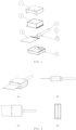
- the wiring system comprises the following elements:
- the upper (1) and lower (2) half-shells are joined to define within them a confined volume adapted to be filled with sealing material (6): in the preferred embodiment described herein, said half-shells have on one side a flat output adapted to the FFC cable (3), whereas on the opposite side they each have a semi-cylindrical output suitable to accommodate the voltage cable (4). Between said two opposing outputs, the half-shells (1, 2) define a closed cavity adapted to accommodate the connection area between the FFC (3) and the voltage cable (4).
- the upper half-shell (1) also has two holes whose function is to enable: in the first, the introduction of the sealing material (6) in liquid or paste form, and in the second, enable the exit of air, so as to prevent incomplete filling of the internal volume with the sealant (6).
- each shell has a semi-toroidal shaped groove suitable to accommodate the O-Ring (5) and to clamp it in a watertight way around the voltage cable (4).
- the coupling system provides first for electrically connecting the FFC cable (3) with the voltage cable (4), e.g. by tin brazing, resistance welding, ultrasonic welding, etc., in which said voltage cable (4) is provided with an O-Ring (5); the assembly thus composed is accommodated inside the shell comprising the lower half-shell (2) which is joined to the upper half-shell (1), after the cable assembly (3, 4) has been assembled and the O-Ring (5) positioned in its proper housing seat.
- the joining of said half-shells (1, 2) can take place by pressure or snap closure, or by heat sealing, ultrasonic welding or gluing.
- the system thus constituted is filled with a sealing material (6) adapted to solidify and then, after solidification, it assumes the joined shape of the compartment of the shell defined by joining the two half-shells (1, 2).
- the sealing material (6) consists of a resin (preferably, but not exclusively, epoxy) and both the half-shells, the upper (1) and lower (2) ones, are made of plastic material, preferably but not limited to, polyamide 66 (PA66).
- resin preferably, but not exclusively, epoxy
- PA66 polyamide 66
- the FCC (3) is selectable from all the known types, whether they are made of polyester or polyimide as an insulator.
- the FCC may be a thin sheet of tin plated copper covered with an insulator made of polyimide (a material whose most common trade name on the market is "Kapton").
- the cable (4) is selectable from known types, said cables being provided with an insulating coating which may be cross-linked polyethylene (XLPE), polyvinyl chloride (PCV), polypropylene (PP), fluorinated ethylene propylene (FEP), ethylene tetrafluoroethylene (ETFE), silicone, rubber, thermoplastic rubbers or the like.
- XLPE cross-linked polyethylene
- PCV polyvinyl chloride
- PP polypropylene
- FEP fluorinated ethylene propylene
- ETFE ethylene tetrafluoroethylene
- the O-Ring (5) is preferably made of rubber.
- the epoxy resin which constitutes the sealing material (6) has excellent adhesion to the polyimide which enables water infiltrations on the FFC/sealant side to be prevented.
- the presence of the O-Ring (5) has a dual function: preventing the exit of resin on the cable side during the injection process thereof into the cavity, but above all preventing water infiltrations on the cable/sealant side.
- epoxy resin would not have good adhesion to the cable (4) as the outer coating material of the latter is usually a cross-linked polyethylene which has difficult adhesion with resins in general.
- the system according to the invention enables a good connection to be obtained between an FCC (3) and an electric cable (4) which is totally watertight, thus preventing degradation of the contacts due to water infiltrations.
Landscapes
- Connector Housings Or Holding Contact Members (AREA)
Applications Claiming Priority (1)
| Application Number | Priority Date | Filing Date | Title |
|---|---|---|---|
| IT102022000004274A IT202200004274A1 (it) | 2022-03-07 | 2022-03-07 | Cablaggio tra cavo e ffc a tenuta stagna |
Publications (1)
| Publication Number | Publication Date |
|---|---|
| EP4243230A1 true EP4243230A1 (de) | 2023-09-13 |
Family
ID=81927772
Family Applications (1)
| Application Number | Title | Priority Date | Filing Date |
|---|---|---|---|
| EP23160575.9A Pending EP4243230A1 (de) | 2022-03-07 | 2023-03-07 | Wasserdichte verdrahtung zwischen kabel und ffc |
Country Status (2)
| Country | Link |
|---|---|
| EP (1) | EP4243230A1 (de) |
| IT (1) | IT202200004274A1 (de) |
Citations (4)
| Publication number | Priority date | Publication date | Assignee | Title |
|---|---|---|---|---|
| EP1058349A1 (de) * | 1999-06-01 | 2000-12-06 | Sumitomo Wiring Systems, Ltd. | Anordnung zum Verbinden von Kabeln zu Flachkabeln |
| EP0888951B1 (de) * | 1997-07-02 | 2002-11-06 | Kabushiki Kaisha Toyota Jidoshokki | Sensoreinbaustrukur für Fahrzeuge |
| US20120100750A1 (en) * | 2009-07-02 | 2012-04-26 | Yazaki Corporation | Connecting structure and connecting method for flexible flat cable |
| CN109987038A (zh) * | 2017-12-06 | 2019-07-09 | 矢崎总业株式会社 | 布线构件连接结构 |
-
2022
- 2022-03-07 IT IT102022000004274A patent/IT202200004274A1/it unknown
-
2023
- 2023-03-07 EP EP23160575.9A patent/EP4243230A1/de active Pending
Patent Citations (4)
| Publication number | Priority date | Publication date | Assignee | Title |
|---|---|---|---|---|
| EP0888951B1 (de) * | 1997-07-02 | 2002-11-06 | Kabushiki Kaisha Toyota Jidoshokki | Sensoreinbaustrukur für Fahrzeuge |
| EP1058349A1 (de) * | 1999-06-01 | 2000-12-06 | Sumitomo Wiring Systems, Ltd. | Anordnung zum Verbinden von Kabeln zu Flachkabeln |
| US20120100750A1 (en) * | 2009-07-02 | 2012-04-26 | Yazaki Corporation | Connecting structure and connecting method for flexible flat cable |
| CN109987038A (zh) * | 2017-12-06 | 2019-07-09 | 矢崎总业株式会社 | 布线构件连接结构 |
Also Published As
| Publication number | Publication date |
|---|---|
| IT202200004274A1 (it) | 2023-09-07 |
Similar Documents
| Publication | Publication Date | Title |
|---|---|---|
| US8011976B2 (en) | Waterproof connector and method for producing the same | |
| US5168124A (en) | Waterproof seal construction for wire harness | |
| US7344408B2 (en) | Waterproof packing, waterproof connector using the same and process for producing waterproof connector | |
| US10770832B2 (en) | Electric cable subassembly | |
| JP5373401B2 (ja) | 一体形成されたシール部材を有するフラットフレキシブルケーブルアセンブリ | |
| US20100300748A1 (en) | Waterproof joint section forming method and wire harness provided with waterproof joint section formed by the method | |
| US8801457B2 (en) | Connecting structure and connecting method for flexible flat cable | |
| JP2000348791A (ja) | フラットケーブルと電線の接続構造 | |
| US9614361B2 (en) | Waterproof seal for electrical assemblies | |
| JP2005005042A (ja) | 防水栓付きケーブル、防水栓付きコネクタケーブル、防水栓付きケーブルの製造方法及び防水栓付きケーブルの端子金具接続構造 | |
| US10027077B2 (en) | Contact point for connecting a flat conductor to a conductor element | |
| JP2013101806A (ja) | 差込プラグ付きコード | |
| US20170141557A1 (en) | Device for sealing an electrical connection | |
| CN113285282B (zh) | 装配有电线的端子以及传感器的固定方法 | |
| US5792989A (en) | Wrap type cable closure end seal | |
| JP2002170627A (ja) | 防水コネクタ及びその製造方法 | |
| US4674816A (en) | Electrical connection system | |
| CN115803977B (zh) | 接头电缆、特别是高压接头电缆、及电缆、特别是高压电缆的接头连接方法 | |
| US8870229B2 (en) | System for connecting hose lines | |
| JP4097175B2 (ja) | シールドコネクタ | |
| JPH07106014A (ja) | コネクタ | |
| KR100312084B1 (ko) | 접속소자를구비한페인과그의제작방법및실행장치 | |
| JP7102466B2 (ja) | ワイヤハーネス | |
| CN114883841A (zh) | 防水型射频连接器及其组装方法 | |
| JP2014229586A (ja) | ワイヤハーネス |
Legal Events
| Date | Code | Title | Description |
|---|---|---|---|
| PUAI | Public reference made under article 153(3) epc to a published international application that has entered the european phase |
Free format text: ORIGINAL CODE: 0009012 |
|
| STAA | Information on the status of an ep patent application or granted ep patent |
Free format text: STATUS: THE APPLICATION HAS BEEN PUBLISHED |
|
| AK | Designated contracting states |
Kind code of ref document: A1 Designated state(s): AL AT BE BG CH CY CZ DE DK EE ES FI FR GB GR HR HU IE IS IT LI LT LU LV MC ME MK MT NL NO PL PT RO RS SE SI SK SM TR |
|
| STAA | Information on the status of an ep patent application or granted ep patent |
Free format text: STATUS: REQUEST FOR EXAMINATION WAS MADE |
|
| 17P | Request for examination filed |
Effective date: 20240312 |
|
| RBV | Designated contracting states (corrected) |
Designated state(s): AL AT BE BG CH CY CZ DE DK EE ES FI FR GB GR HR HU IE IS IT LI LT LU LV MC ME MK MT NL NO PL PT RO RS SE SI SK SM TR |