EP4244098B1 - Vorrichtung und verfahren zur handhabung von twistlocks - Google Patents
Vorrichtung und verfahren zur handhabung von twistlocks Download PDFInfo
- Publication number
- EP4244098B1 EP4244098B1 EP20961072.4A EP20961072A EP4244098B1 EP 4244098 B1 EP4244098 B1 EP 4244098B1 EP 20961072 A EP20961072 A EP 20961072A EP 4244098 B1 EP4244098 B1 EP 4244098B1
- Authority
- EP
- European Patent Office
- Prior art keywords
- vehicle
- robot
- corner fitting
- handling
- twistlocks
- Prior art date
- Legal status (The legal status is an assumption and is not a legal conclusion. Google has not performed a legal analysis and makes no representation as to the accuracy of the status listed.)
- Active
Links
Images

Classifications
-
- B—PERFORMING OPERATIONS; TRANSPORTING
- B25—HAND TOOLS; PORTABLE POWER-DRIVEN TOOLS; MANIPULATORS
- B25J—MANIPULATORS; CHAMBERS PROVIDED WITH MANIPULATION DEVICES
- B25J15/00—Gripping heads and other end effectors
- B25J15/0033—Gripping heads and other end effectors with gripping surfaces having special shapes
-
- B—PERFORMING OPERATIONS; TRANSPORTING
- B25—HAND TOOLS; PORTABLE POWER-DRIVEN TOOLS; MANIPULATORS
- B25J—MANIPULATORS; CHAMBERS PROVIDED WITH MANIPULATION DEVICES
- B25J19/00—Accessories fitted to manipulators, e.g. for monitoring, for viewing; Safety devices combined with or specially adapted for use in connection with manipulators
- B25J19/02—Sensing devices
- B25J19/021—Optical sensing devices
- B25J19/023—Optical sensing devices including video camera means
-
- B—PERFORMING OPERATIONS; TRANSPORTING
- B25—HAND TOOLS; PORTABLE POWER-DRIVEN TOOLS; MANIPULATORS
- B25J—MANIPULATORS; CHAMBERS PROVIDED WITH MANIPULATION DEVICES
- B25J5/00—Manipulators mounted on wheels or on carriages
- B25J5/007—Manipulators mounted on wheels or on carriages mounted on wheels
-
- B—PERFORMING OPERATIONS; TRANSPORTING
- B25—HAND TOOLS; PORTABLE POWER-DRIVEN TOOLS; MANIPULATORS
- B25J—MANIPULATORS; CHAMBERS PROVIDED WITH MANIPULATION DEVICES
- B25J5/00—Manipulators mounted on wheels or on carriages
- B25J5/02—Manipulators mounted on wheels or on carriages travelling along a guideway
-
- B—PERFORMING OPERATIONS; TRANSPORTING
- B25—HAND TOOLS; PORTABLE POWER-DRIVEN TOOLS; MANIPULATORS
- B25J—MANIPULATORS; CHAMBERS PROVIDED WITH MANIPULATION DEVICES
- B25J9/00—Program-controlled manipulators
- B25J9/0093—Program-controlled manipulators co-operating with conveyor means
-
- B—PERFORMING OPERATIONS; TRANSPORTING
- B25—HAND TOOLS; PORTABLE POWER-DRIVEN TOOLS; MANIPULATORS
- B25J—MANIPULATORS; CHAMBERS PROVIDED WITH MANIPULATION DEVICES
- B25J9/00—Program-controlled manipulators
- B25J9/16—Program controls
- B25J9/1679—Program controls characterised by the tasks executed
-
- B—PERFORMING OPERATIONS; TRANSPORTING
- B25—HAND TOOLS; PORTABLE POWER-DRIVEN TOOLS; MANIPULATORS
- B25J—MANIPULATORS; CHAMBERS PROVIDED WITH MANIPULATION DEVICES
- B25J9/00—Program-controlled manipulators
- B25J9/16—Program controls
- B25J9/1694—Program controls characterised by use of sensors other than normal servo-feedback from position, speed or acceleration sensors, perception control, multi-sensor controlled systems, sensor fusion
- B25J9/1697—Vision controlled systems
-
- B—PERFORMING OPERATIONS; TRANSPORTING
- B65—CONVEYING; PACKING; STORING; HANDLING THIN OR FILAMENTARY MATERIAL
- B65D—CONTAINERS FOR STORAGE OR TRANSPORT OF ARTICLES OR MATERIALS, e.g. BAGS, BARRELS, BOTTLES, BOXES, CANS, CARTONS, CRATES, DRUMS, JARS, TANKS, HOPPERS, FORWARDING CONTAINERS; ACCESSORIES, CLOSURES, OR FITTINGS THEREFOR; PACKAGING ELEMENTS; PACKAGES
- B65D90/00—Component parts, details or accessories for large containers
- B65D90/0006—Coupling devices between containers, e.g. ISO-containers
- B65D90/0013—Twist lock
- B65D90/002—Apparatus for manual or automatic installation/removal of twist-lock
-
- B—PERFORMING OPERATIONS; TRANSPORTING
- B60—VEHICLES IN GENERAL
- B60P—VEHICLES ADAPTED FOR LOAD TRANSPORTATION OR TO TRANSPORT, TO CARRY, OR TO COMPRISE SPECIAL LOADS OR OBJECTS
- B60P7/00—Securing or covering of load on vehicles
- B60P7/06—Securing of load
- B60P7/13—Securing freight containers or forwarding containers on vehicles
- B60P7/132—Securing freight containers or forwarding containers on vehicles twist-locks for containers or frames
-
- G—PHYSICS
- G05—CONTROLLING; REGULATING
- G05B—CONTROL OR REGULATING SYSTEMS IN GENERAL; FUNCTIONAL ELEMENTS OF SUCH SYSTEMS; MONITORING OR TESTING ARRANGEMENTS FOR SUCH SYSTEMS OR ELEMENTS
- G05B2219/00—Program-control systems
- G05B2219/30—Nc systems
- G05B2219/40—Robotics, robotics mapping to robotics vision
- G05B2219/40252—Robot on track, rail moves only back and forth
-
- G—PHYSICS
- G05—CONTROLLING; REGULATING
- G05B—CONTROL OR REGULATING SYSTEMS IN GENERAL; FUNCTIONAL ELEMENTS OF SUCH SYSTEMS; MONITORING OR TESTING ARRANGEMENTS FOR SUCH SYSTEMS OR ELEMENTS
- G05B2219/00—Program-control systems
- G05B2219/30—Nc systems
- G05B2219/40—Robotics, robotics mapping to robotics vision
- G05B2219/40298—Manipulator on vehicle, wheels, mobile
Definitions
- Example embodiments of the present disclosure generally relate to the field of twistlock handling, and more specifically, to an apparatus and a method for handling twistlocks on a moving vehicle with robots.
- Twistlocks are commonly used together with a shipping container to for example lock the container onto a truck or a ship.
- the container Upon loading the container from the truck onto the ship, the container needs to be unlocked from the truck through handling the twistlocks first, and is then transferred from the truck onto the ship.
- the container Upon unloading the container from the ship, the container needs to be locked onto the truck through handling the twistlocks after being transferred onto the truck.
- Modem ports aim to realize high efficiency and automation of container loading and unloading.
- twistlock handling becomes a stumbling block for such an automation process.
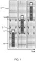
- FIG. 1 illustrates a conventional process for handling twistlocks on a vehicle 1 in a twistlock handling station 3.
- three twistlocks (not shown) are provided, including two side twistlocks and one middle twistlock, so as to lock the container 4 onto the vehicle 1.
- the vehicle 1 drives into the twistlock handling station 3.
- three robots 2 are fixed on the ground so as to handle the corresponding twistlocks. Then, as shown in the central part of Fig.
- the vehicle 1 stops at an appropriate position at which the robots 2 at each side of the vehicle 1 handle the corresponding twistlocks, e.g., dismounting the twistlocks from the vehicle 1 or mounting the twistlocks onto the vehicle 1.
- the vehicle 1 drives out of the twistlock handling station 3, as shown in the right part of Fig. 1 .
- the handling of the twistlocks is discrete in time.
- the vehicle 1 drives into the twistlock handling station 3, stops at the appropriate position and waits for the robots 2 to handle the twistlocks. After the handling of all the twistlocks is completed, the vehicle 1 drives out of the twistlock handling station 3.
- each side of the vehicle 1 would be provided with no less than three robots, which would result in a huge cost.
- the twistlock handling station 3 would occupy a large area.
- the total length of the twistlock handling station 3 is about three times the length of the container 4, which will lead to a large turning circle of the moving path of the vehicle 1 and lower entire quay efficiency.
- WO 2012/141658 A2 describes an automatic stevedore remote station having a camera, a gripper and a twister which can move to the detected inter-box connector and remove/install an inter-box connector from/onto a shipping container.
- US 2014/0067188 Al describes a railway maintenance device configured to decouple and/or attach rail vehicles.
- WO 2020/009656 Al describes an apparatus for container coning and/or deconing.
- WO 2019/007318 Al describes an automatic mounting and dismounting system for a container twistlock.
- example embodiments of the present disclosure provide solutions for handling twistlocks with robots.
- example embodiments of the present disclosure provide an apparatus for handling twistlocks configured to lock a container onto a vehicle.
- the apparatus comprises a robot comprising a gripper configured to grip one of the twistlocks to be mounted onto or dismounted from a corner fitting of the container; a visual sensor arranged on the robot and configured to capture a first image of the corner fitting when the vehicle is moving in a twistlock handling station; and a control unit.
- the control unit is configured to obtain, from the visual sensor, the first image of the corner fitting; determine, based on the first image, a first position of the corner fitting at the moment when the first image is captured by the visual sensor; determine a handling position of the gripper for the one of the twistlocks, at which the gripper is to be aligned with the corner fitting, based on the first position of the corner fitting and a position correction parameter representative of a predictive displacement of the corner fitting within a predetermined response time of the robot; and send the handling position to the robot such that the gripper moves to the handling position to handle the one of the twistlocks during the moving of the vehicle.
- the robot can locate the corner fitting on the container in real-time.
- the robot has abilities to track and handle the twistlocks on a moving vehicle.
- only one robot is needed at each side of the moving vehicle to handle the corresponding twistlocks at each side of the vehicle.
- the number of the robots to be used in the twistlock handling station could be reduced greatly, leading to a lower overall cost.
- the area occupied by the twistlock handling station could also be reduced, improving the overall efficiency of the quay.
- the robot is fixed on ground, or arranged on a movable base, or slidably arranged on a guide rail. With these embodiments, the robot may be arranged at any appropriate sites so as to handle the twistlocks on the vehicle in an efficient way.
- the apparatus when the robot is arranged on the movable base or slidably arranged on the guide rail, the apparatus further comprises a proximity sensor arranged on the robot and configured to detect a rough position of the vehicle after the vehicle enters into the twistlock handling station.
- the control unit is further configured to obtain the rough position of the vehicle from the proximity sensor; and cause the robot to move towards the vehicle based on the rough position of the vehicle.
- the proximity sensor could get the rough position of the vehicle in the twistlock handling station such that the robot could be guided to move towards the vehicle quickly. In this way, the handling speed of the twistlocks on the vehicle could be further improved and the length of the twistlock handling station could be further reduced.
- control unit is further configured to cause the robot to move towards a next one of the twistlocks after the handling of the one of the twistlocks is completed.
- the robot could move towards the next twistlock quickly. In this way, the twistlocks at each side of the vehicle could be handled one after the other rapidly, further improving the handling speed of the twistlocks.
- the position correction parameter is preset.
- the vehicle could move at a substantially constant speed in the twistlock handling station.
- the vehicle could be an automatic container truck running at a constant speed.
- control unit is further configured to: determine the position correction parameter dynamically based on a speed of the vehicle and the predetermined response time of the robot.
- the position correction parameter could be determined dynamically based on the speed of the vehicle. Since the speed of the vehicle is a continuous physical quantity and would not be changed abruptly, it could be supposed as constant in a short time. Thus, the position correction parameter could ensure the robot tracks the corner fitting in real-time.
- the visual senor is further configured to capture second and third images of the corner fitting prior to capturing the first image of the corner fitting
- the control unit is further configured to: obtain, from the visual sensor, the second and third images of the corner fitting; determine, based on the second and third images respectively, second and third positions of the corner fitting at the moments when the second and third images are captured by the visual sensor; and determine the speed of the vehicle based on the second and third positions of the corner fitting.
- the real-time speed of the corner fitting could be determined based on the images obtained by the visual sensor, without the need of any additional sensors.
- the speed of the vehicle is detected by a camera arranged in the twistlock handling station or a GPS device arranged on the vehicle. With these embodiments, the speed of the vehicle could be determined precisely through the use of the camera or the GPS device.
- example embodiments of the present disclosure provide a method for handling twistlocks configured to lock a container onto a vehicle.
- the method comprises: obtaining, from a visual sensor arranged on a robot, a first image of a corner fitting of the container, wherein the robot comprises a gripper configured to grip one of the twistlocks to be mounted onto or dismounted from the corner fitting, and wherein the visual sensor is configured to capture the first image of the corner fitting when the vehicle is moving in a twistlock handling station; determining, based on the first image, a first position of the corner fitting at the moment when the first image is captured by the visual sensor; determining a handling position of the gripper for the one of the twistlocks, at which the gripper is to be aligned with the corner fitting, based on the first position of the corner fitting and a position correction parameter representative of a predictive displacement of the corner fitting within a predetermined response time of the robot; and sending the handling position to the robot such that the gripper moves to the handling position to handle the one of the twistlock
- the robot is fixed on ground, or arranged on a movable base, or slidably arranged on a guide rail.
- the method when the robot is arranged on the movable base or slidably arranged on the guide rail, the method further comprises: obtaining a rough position of the vehicle detected by a proximity sensor arranged on the robot after the vehicle enters into the twistlock handling station; and causing the robot to move towards the vehicle based on the rough position of the vehicle.
- the method further comprises: causing the robot to move towards a next one of the twistlocks after the handling of the one of the twistlocks is completed.
- the position correction parameter is preset.
- the method further comprises: determining the position correction parameter dynamically based on a speed of the vehicle and the predetermined response time of the robot.
- the visual senor is further configured to capture second and third images of the corner fitting prior to capturing the first image of the corner fitting
- the method further comprises: obtaining, from the visual sensor, the second and third images of the corner fitting; determining, based on the second and third images respectively, second and third positions of the corner fitting at the moments when the second and third images are captured by the visual sensor; and determining the speed of the vehicle based on the second and third positions of the corner fitting.
- the speed of the vehicle is detected by a camera arranged in the twistlock handling station or a GPS device arranged on the vehicle.
- example embodiments of the present disclosure provide a system for handling twistlocks, comprising: a computer processor coupled to a computer-readable memory unit, the memory unit comprising instructions that when executed by the computer processor implements the method according to the second aspect of the present disclosure.
- example embodiments of the present disclosure provide a computer readable medium having instructions stored thereon, the instructions, when executed on at least one processor, cause the at least one processor to perform the method according to the second aspect of the present disclosure.
- each side of the vehicle needs be provided with no less than three robots, which would result in a huge cost; moreover, the conventional twistlock handling station would occupy a large area, which will lead to a large turning circle of the moving path of the vehicle and lower entire quay efficiency.
- the vision-based control technology and position correction technology are used so as to handle the twistlocks when the vehicle is moving in the twistlock handling station.
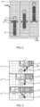
- Fig. 2 illustrates an example process for handling twistlocks on the vehicle 1 in the twistlock handling station 3 in accordance with an embodiment of the present disclosure
- Fig. 3 illustrates an example process for handling a first twistlock on the vehicle 1 in the twistlock handling station 3 in accordance with an embodiment of the present disclosure
- the twistlocks are configured to be mated with corner fittings of a container 4 so as to lock the container 4 onto the vehicle 1.
- the first twistlock is arranged at the front of the vehicle 1, i.e., closer to the head of the vehicle 1 than other twistlocks.
- a plurality of corner fittings are provided at each side of the container 4 so as to receive the corresponding twistlocks and thus lock the container 4 onto the vehicle 1.
- the number of the corner fittings at each side of the container 4 may be three, including two side corner fittings to be mated with side twistlocks and one middle corner fitting to be mated with a middle twistlock.
- the number of the corner fittings at each side of the vehicle 1 may be more or less than three. The scope of the present disclosure is not intended to be limited in this respect.
- one robot 2 is arranged at each side of the vehicle 1.
- the robot 2 may be fixed on the ground or other platforms.
- the robot 2 may be of any known types or other types available in the future.
- the robot 2 includes a gripper 201 configured to grip one of the twistlocks to be mounted onto or dismounted from the corner fitting of the container 4.
- the gripper 20 has the ability to deal with both the side and middle twistlocks.
- a visual senor is arranged on the robot 2 to capture a first image of the corner fitting when the vehicle 1 is moving in the twistlock handling station 3. Based on the first image of the corner fitting, the position of the corner fitting could be determined by a control unit, as described in detail hereinafter.
- the control unit described herein is configured to obtain the first image of the corner fitting from the visual sensor and determine a first position of the corner fitting based on the first image.
- the first position refers to the current position of the corner fitting at the moment when the first image is captured by the visual sensor.
- the gripper 201 needs to handle the corresponding twistlock. In some cases, upon loading the container 4 from the vehicle 1 onto the ship, the gripper 201 would need to grip the twistlock and dismount the twistlock from the corner fitting of the container 4. In some other cases, after the container 4 is unloaded from the ship onto the vehicle 1, the gripper 201 would need to grip the twistlock and mount the twistlock onto the corner fitting of the container 4.
- the gripper 201 Since the twistlock is moving continuously on the vehicle 1, the gripper 201 would not be able to grip the twistlock successfully at the first position. This is because the twistlock would have reached a next position when the gripper 201 moves to the first position. To avoid that the gripper 201 will always move to a previous position of the twistlock, a predictive position correction may be applied to the first position of the twistlock. Specifically, the control unit may determine a handling position of the gripper 201 for the twistlock to be handled based on the first position of the corner fitting and a position correction parameter. The gripper 201 is to be aligned with the corner fitting at the handling position. In other words, the gripper 201 would be able to insert the twistlock into the corner fitting or grip the twistlock mounted on the corner fitting successfully at the handling position.
- the position correction parameter is representative of a predictive displacement of the corner fitting within a predetermined response time of the robot 2.
- the predetermined response time of the robot 2 refers to the time from the moment when an image is captured by the visual sensor to the moment when the robot 2 arrives at a desired position.
- the predetermined response time of the robot 2 may be supposed to be substantially constant.
- control unit may send the handling position to the robot 2.
- the robot 2 may translate the handling position into angle values of joints of the robot 2. Thereafter, motors of the joints rotate according to the angle values and the gripper 201 moves to the handling position to handle the twistlock during the moving of the vehicle 1.
- the robot 2, the visual sensor, and the control unit as described above may form an apparatus for handling the twistlocks.
- the apparatus for handling the twistlocks is adapted to handle each of the twistlocks at one side of the vehicle 1 one after the other when the vehicle 1 is moving in the twistlock handling station 3. Taking the process of dismounting the twistlocks from the corner fittings as an example, the specific operations of the apparatus may be as below.
- the first twistlock is handled by the robot 2.
- the gripper 201 may move together with the first twistlock and implement the handling of the first twistlock.
- the robot 2 would wait for a second one of the twistlocks to arrive and then handle it. Finally, as shown in the right part of Fig. 2 , the robot 2 would wait for a third one of the twistlocks to arrive and then handle it.
- the specific process of mounting the twistlocks onto the corner fittings is analogous to the process of dismounting the twistlocks as described above, and would not be described in detail herein any more.
- the twistlocks at the other side of the vehicle 1 may be handled in the similar manner and would not be described in detail herein any more likewise.
- the robot 2 can locate the corner fitting on the container 4 in real-time. Hence, the robot 2 has the abilities to track and handle the twistlocks on the moving vehicle 1. Moreover, only one robot 2 is needed at each side of the moving vehicle 1 to handle the corresponding twistlocks at each side of the vehicle 1. Compared with the conventional solution for handling the twistlocks, the number of the robots to be used in the twistlock handling station 3 could be reduced greatly, from six to two, leading to a lower overall cost. Moreover, the area occupied by the twistlock handling station 3 could also be reduced. Specifically, the length of the twistlock handling station 3 could be decreased from three times to two times of the length of the container 4, improving the overall efficiency of the quay.
- the position correction parameter may be preset.
- the vehicle 1 could be an automatic container truck running at a constant speed.
- the predictive displacement of the corner fitting within the predetermined response time would be substantially constant.
- the first position of the corner fitting could be corrected accurately to obtain the actual handling position of the gripper 201.
- the control unit may be further configured to determine the position correction parameter dynamically based on the speed of the vehicle 1 and the predetermined response time of the robot 2. That is, the speed of the vehicle 1 may be multiplied by the predetermined response time of the robot 2 to obtain the predictive displacement of the corner fitting during the predetermined response time.
- the position correction parameter could be determined dynamically based on the speed of the vehicle 1. Since the speed of the vehicle 1 is a continuous physical quantity and would not be changed abruptly, it could be supposed as constant in a short time. Thus, the position correction parameter could ensure the robot 2 tracks the corner fitting in real-time.
- the speed of the vehicle 1 may be determined in various manners, as described in detail hereinafter.
- the visual senor is further configured to capture second and third images of the corner fitting prior to capturing the first image of the corner fitting.
- the control unit may obtain the second and third images of the corner fitting from the visual sensor. Then, the control unit determines, based on the second and third images respectively, second and third positions of the corner fitting at the moments when the second and third images are captured by the visual sensor. Then, the control unit determines the speed of the vehicle 1 based on the second and third positions of the corner fitting. Specifically, since the time interval between the capturing of the second and third images is known, the speed of the vehicle 1 may be obtained based on the time interval and the second and third positions of the corner fitting. With these embodiments, the real-time speed of the corner fitting could be determined based on the images obtained by the visual sensor, without the need of any additional sensors.
- the speed of the vehicle 1 is detected by a camera arranged in the twistlock handling station 3.
- the camera may collect real-time images of the vehicle 1 and send them to the control unit. Then, the control unit may determine the speed of the vehicle 1 based on the collected real-time images.
- the speed of the vehicle 1 is detected by a GPS device arranged on the vehicle 1. With these embodiments, the speed of the vehicle 1 could be determined precisely through the use of the camera or the GPS device. In other embodiments, the speed of the vehicle 1 may be detected in other manners. The scope of the present disclosure is not intended to be limited in this respect.
- the robot 2 may be movable in the twistlock handling station 3.
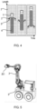
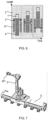
- Figs. 4-7 illustrate such embodiments of the robot 2.
- the robot 2 is arranged on a movable base 5, such as an automated guided vehicle (AGV).
- AGV automated guided vehicle
- the robot 2 is slidably arranged on a guide rail 6.
- the apparatus for handling twistlocks further comprises a proximity sensor arranged on the robot 2.
- the proximity sensor is configured to detect a rough position of the vehicle 1 after the vehicle 1 enters into the twistlock handling station 3. Then, the control unit obtains the rough position of the vehicle 1 from the proximity sensor and cause the robot 2 to move towards the vehicle 1 based on the rough position of the vehicle 1.
- the proximity sensor could get the rough position of the vehicle 1 in the twistlock handling station 3 such that the robot 2 could be guided to move towards the vehicle 1 quickly.
- the movable base 5 stands still, and the robot 2 locates, tracks, and handles the twistlock dynamically.
- the specific operations of the apparatus may be as below.
- the movable base 5 moves near to the first twistlock
- the movable base 5 stands still such that the first twistlock is handled by the robot 2.
- the gripper 201 may move together with the first twistlock and implement the handling of the first twistlock.
- the robot 2 would move near to a second one of the twistlocks quickly after the handling of the first twistlock is completed, and the robot 2 locates, tracks, and handles the second twistlock dynamically while the movable base 5 stands still.
- the robot 2 would move near to a third one of the twistlocks quickly after the handling of the second twistlock is completed, and the robot 2 locates, tracks, and handles the third twistlock dynamically while the movable base 5 stands still.
- the specific process of mounting the twistlocks onto the corner fittings is analogous to the process of dismounting the twistlocks as described above, and would not be described in detail herein any more.
- the twistlocks at the other side of the vehicle 1 may be handled in the similar manner and would not be described in detail herein any more likewise.
- the handling speed of the twistlocks on the vehicle 1 could be further improved and the length of the twistlock handling station 3 could be further reduced.
- the length of the twistlock handling station 3 could be decreased from three times to about one time of the length of the container 4, improving the overall efficiency of the quay.
- the robot 2 on the movable base 5 could move to anywhere on the port taking the traffic condition on the quay and the berth condition of the ship into account. If one quay has very urgent loading and unloading task, the robot 2 from another free quay can move to the busy quay to support the handling of the twistlocks in the busy quay.
- the apparatus for handling twistlocks further comprises a proximity sensor arranged on the robot 2.
- the proximity sensor is configured to detect a rough position of the vehicle 1 after the vehicle 1 enters into the twistlock handling station 3. Then, the control unit obtains the rough position of the vehicle 1 from the proximity sensor and cause the robot 2 to move towards the vehicle 1 based on the rough position of the vehicle 1. Then, the movable base 5 stands still on the guide rail 6, and the robot 2 locates, tracks, and handles the twistlock dynamically.
- the specific operations of the apparatus for handling twistlocks may be as below.
- the robot 2 moves near to the first twistlock on the guide rail 6, the robot 2 stands still such that the first twistlock is handled by the robot 2.
- the gripper 201 may move together with the first twistlock and implement the handling of the first twistlock. Then, as shown in the central part of Fig.
- the robot 2 would move near to a second one of the twistlocks on the guide rail 6 quickly after the handling of the first twistlock is completed, and the robot 2 locates, tracks, and handles the second twistlock dynamically while the robot 2 stands still.
- the robot 2 would move near to a third one of the twistlocks on the guide rail 6 quickly after the handling of the second twistlock is completed, and the robot 2 locates, tracks, and handles the third twistlock dynamically while the robot 2 stands still.
- the specific process of mounting the twistlocks onto the corner fittings is analogous to the process of dismounting the twistlocks as described above, and would not be described in detail herein any more.
- the twistlocks at the other side of the vehicle 1 may be handled in the similar manner and would not be described in detail herein any more likewise.
- Example embodiments of the present disclosure also provide a method for handling twistlocks.
- Fig. 8 illustrates a flowchart of a method 800 for handling twistlocks in accordance with embodiments of the present disclosure.
- the method 800 comprises: at 810, obtaining, from a visual sensor arranged on a robot, a first image of a corner fitting of the container, wherein the robot comprises a gripper configured to grip one of the twistlocks to be mounted onto or dismounted from the corner fitting, and wherein the visual sensor is configured to capture the first image of the corner fitting when the vehicle is moving in a twistlock handling station; at 820, determining, based on the first image, a first position of the corner fitting at the moment when the first image is captured by the visual sensor; at 830, determining a handling position of the gripper for the one of the twistlocks, at which the gripper is to be aligned with the corner fitting, based on the first position of the corner fitting and a position correction parameter representative of a predictive displacement of the corner fitting within
- the robot is fixed on ground, or arranged on a movable base, or slidably arranged on a guide rail.
- the method when the robot is arranged on the movable base or slidably arranged on the guide rail, the method further comprises: obtaining a rough position of the vehicle detected by a proximity sensor arranged on the robot after the vehicle enters into the twistlock handling station; and causing the robot to move towards the vehicle based on the rough position of the vehicle.
- the method further comprises: causing the robot to move towards a next one of the twistlocks after the handling of the one of the twistlocks is completed.
- the position correction parameter is preset.
- the method further comprises: determining the position correction parameter dynamically based on a speed of the vehicle and the predetermined response time of the robot.
- the visual senor is further configured to capture second and third images of the corner fitting prior to capturing the first image of the corner fitting
- the method further comprises: obtaining, from the visual sensor, the second and third images of the corner fitting; determining, based on the second and third images respectively, second and third positions of the corner fitting at the moments when the second and third images are captured by the visual sensor; and determining the speed of the vehicle based on the second and third positions of the corner fitting.
- the speed of the vehicle is detected by a camera arranged in the twistlock handling station or a GPS device arranged on the vehicle.
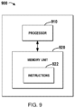
- a system 900 for handling twistlocks is provided.
- Fig. 9 illustrates a schematic diagram of the system 900 for handling twistlocks in accordance with embodiments of the present disclosure.
- the system 900 may comprise a computer processor 910 coupled to a computer-readable memory unit 920, and the memory unit 920 comprises instructions 922.
- the instructions 922 may implement the method for handling twistlocks as described in the preceding paragraphs, and details will be omitted hereinafter.
- a computer readable medium for handling twistlocks has instructions stored thereon, and the instructions, when executed on at least one processor, may cause at least one processor to perform the method for handling twistlocks as described in the preceding paragraphs, and details will be omitted hereinafter.
- various embodiments of the present disclosure may be implemented in hardware or special purpose circuits, software, logic or any combination thereof. Some aspects may be implemented in hardware, while other aspects may be implemented in firmware or software which may be executed by a controller, microprocessor or other computing device. While some aspects of embodiments of the present disclosure are illustrated and described as block diagrams, flowcharts, or using some other pictorial representation, it will be appreciated that the blocks, apparatus, systems, techniques or methods described herein may be implemented in, as non-limiting examples, hardware, software, firmware, special purpose circuits or logic, general purpose hardware or controller or other computing devices, or some combination thereof.
- the present disclosure also provides at least one computer program product tangibly stored on a non-transitory computer readable storage medium.
- the computer program product includes computer-executable instructions, such as those included in program modules, being executed in a device on a target real or virtual processor, to carry out the process or method as described above with reference to Figs. 2-8 .
- program modules include routines, programs, libraries, objects, classes, components, data structures, or the like that perform particular tasks or implement particular abstract data types.
- the functionality of the program modules may be combined or split between program modules as ideal in various embodiments.
- Machine-executable instructions for program modules may be executed within a local or distributed device. In a distributed device, program modules may be located in both local and remote storage media.
- Program code for carrying out methods of the present disclosure may be written in any combination of one or more programming languages. These program codes may be provided to a processor or controller of a general purpose computer, special purpose computer, or other programmable data processing apparatus, such that the program codes, when executed by the processor or controller, cause the functions/operations specified in the flowcharts and/or block diagrams to be implemented.
- the program code may execute entirely on a machine, partly on the machine, as a stand-alone software package, partly on the machine and partly on a remote machine or entirely on the remote machine or server.
- the above program code may be embodied on a machine readable medium, which may be any tangible medium that may contain, or store a program for use by or in connection with an instruction execution system, apparatus, or device.
- the machine readable medium may be a machine readable signal medium or a machine readable storage medium.
- a machine readable medium may include but not limited to an electronic, magnetic, optical, electromagnetic, infrared, or semiconductor system, apparatus, or device, or any suitable combination of the foregoing.
- machine readable storage medium More specific examples of the machine readable storage medium would include an electrical connection having one or more wires, a portable computer diskette, a hard disk, a random access memory (RAM), a read-only memory (ROM), an erasable programmable read-only memory (EPROM or Flash memory), an optical fiber, a portable compact disc read-only memory (CD-ROM), an optical storage device, a magnetic storage device, or any suitable combination of the foregoing.
- RAM random access memory
- ROM read-only memory
- EPROM or Flash memory erasable programmable read-only memory
- CD-ROM portable compact disc read-only memory
- magnetic storage device or any suitable combination of the foregoing.
Landscapes
- Engineering & Computer Science (AREA)
- Mechanical Engineering (AREA)
- Robotics (AREA)
- Multimedia (AREA)
- Manipulator (AREA)
Claims (15)
- Vorrichtung zur Handhabung von Twistlocks, die so konfiguriert sind, dass sie einen Container (4) auf einem Fahrzeug (1) verriegeln, wobei die Vorrichtung umfasst:einen Roboter (2) mit einem Greifer (201), der so konfiguriert ist, dass er einen der Twistlocks greift, die an einem Eckbeschlag des Containers angebracht oder von diesem abgenommen werden sollen;einen visuellen Sensor, der an dem Roboter angeordnet und so konfiguriert ist, dass er ein erstes Bild des Eckbeschlags erfasst, wenn sich das Fahrzeug in einer Twistlock-Handhabungsstation (3) bewegt; undeine Steuereinheit, die so konfiguriert ist:von dem visuellen Sensor das erste Bild des Eckbeschlags zu erhalten;auf der Grundlage des ersten Bildes eine erste Position des Eckbeschlags in dem Moment zu bestimmen, in dem das erste Bild von dem visuellen Sensor erfasst wird;eine Handhabungsposition des Greifers für einen der Twistlocks zu bestimmen, an der der Greifer mit dem Eckbeschlag ausgerichtet werden soll, basierend auf der ersten Position des Eckbeschlags und einem Positionskorrekturparameter, der eine voraussichtliche Verschiebung des Eckbeschlags innerhalb einer vorgegebenen Reaktionszeit des Roboters darstellt; unddie Handhabungsposition an den Roboter zu senden, so dass sich der Greifer zur Handhabung des einen der Twistlocks während der Bewegung des Fahrzeugs zur Handhabungsposition bewegt.
- Vorrichtung nach Anspruch 1, wobei der Roboter am Boden befestigt ist oder auf einer beweglichen Basis (5) angeordnet ist oder verschiebbar auf einer Führungsschiene (6) angeordnet ist.
- Vorrichtung nach Anspruch 2, wobei die Vorrichtung, wenn der Roboter auf der beweglichen Basis oder verschiebbar auf der Führungsschiene angeordnet ist, ferner einen Näherungssensor umfasst, der auf dem Roboter angeordnet und so konfiguriert ist, dass er eine ungefähre Position des Fahrzeugs erfasst, nachdem das Fahrzeug in die Twistlock-Handhabungsstation einfährt, und
wobei die Steuereinheit ferner so konfiguriert ist:die ungefähre Position des Fahrzeugs von dem Näherungssensor zu erhalten; undden Roboter dazu zu veranlassen, sich auf der Grundlage der ungefähren Position des Fahrzeugs auf das Fahrzeug zuzubewegen. - Vorrichtung nach Anspruch 3, wobei die Steuereinheit ferner so konfiguriert ist:
den Roboter zu veranlassen, sich auf einen nächsten der Twistlocks zuzubewegen, nachdem die Handhabung des einen der Twistlocks abgeschlossen ist. - Vorrichtung nach Anspruch 1, wobei der Positionskorrekturparameter voreingestellt ist.
- Vorrichtung nach Anspruch 1, wobei die Steuereinheit ferner so konfiguriert ist, dass sie
den Positionskorrekturparameter dynamisch auf der Grundlage einer Geschwindigkeit des Fahrzeugs und der vorgegebenen Reaktionszeit des Roboters bestimmt. - Vorrichtung nach Anspruch 6, wobei der visuelle Sensor ferner so konfiguriert ist, dass er ein zweites und ein drittes Bild des Eckbeschlags vor der Aufnahme des ersten Bildes des Eckbeschlags erfasst, und
wobei die Steuereinheit ferner so konfiguriert ist:vom visuellen Sensor das zweite und dritte Bild des Eckbeschlags zu erhalten;auf der Grundlage des zweiten bzw. dritten Bildes die zweite und dritte Position des Eckbeschlags zu den Zeitpunkten zu bestimmen, zu denen das zweite und dritte Bild vom visuellen Sensor erfasst werden; unddie Geschwindigkeit des Fahrzeugs auf der Grundlage der zweiten und dritten Position des Eckbeschlags zu bestimmen. - Vorrichtung nach Anspruch 6, wobei die Geschwindigkeit des Fahrzeugs durch eine in der Twistlock-Handhabungsstation angeordnete Kamera oder ein am Fahrzeug angeordnetes GPS-Gerät erfasst wird.
- Verfahren (800) zum Handhaben von Twistlocks, die so konfiguriert sind, dass sie einen Container auf einem Fahrzeug verriegeln, wobei das Verfahren umfasst:Erhalten (810) eines ersten Bildes eines Eckbeschlags des Containers von einem visuellen Sensor, der an einem Roboter angeordnet ist, wobei der Roboter einen Greifer umfasst, der so konfiguriert ist, dass er einen der Twistlocks greift, die an dem Eckbeschlag anzubringen oder von diesem abzunehmen sind, und wobei der visuelle Sensor so konfiguriert ist, dass er das erste Bild des Eckbeschlags erfasst, wenn sich das Fahrzeug in einer Twistlock-Handhabungsstation bewegt;Bestimmen (820), basierend auf dem ersten Bild, einer ersten Position des Eckbeschlags in dem Moment, in dem das erste Bild durch den visuellen Sensor erfasst wird;Bestimmen (830) einer Handhabungsposition des Greifers für einen der Twistlocks, an der der Greifer mit dem Eckbeschlag ausgerichtet werden soll, basierend auf der ersten Position des Eckbeschlags und einem Positionskorrekturparameter, der eine voraussichtliche Verschiebung des Eckbeschlags innerhalb einer vorbestimmten Reaktionszeit des Roboters darstellt; undSenden (840) der Handhabungsposition an den Roboter, so dass sich der Greifer zur Handhabung des einen der Twistlocks während der Bewegung des Fahrzeugs zur Handhabungsposition bewegt.
- Verfahren nach Anspruch 9, wobei der Roboter am Boden befestigt oder auf einer beweglichen Basis oder verschiebbar auf einer Führungsschiene angeordnet ist, insbesondere
wobei, wenn der Roboter auf der beweglichen Basis angeordnet ist oder verschiebbar auf der Führungsschiene angeordnet ist, das Verfahren ferner umfasst:Erhalten einer ungefähren Position des Fahrzeugs, die durch einen auf dem Roboter angeordneten Näherungssensor erfasst wird, nachdem das Fahrzeug in die Twistlock-Handhabungsstation einfährt; undBewirken, dass sich der Roboter auf der Grundlage der ungefähren Position des Fahrzeugs auf das Fahrzeug zubewegt;insbesondere ferner umfassend:
Bewirken, dass sich der Roboter zu einem nächsten der Twistlocks bewegt, nachdem die Handhabung des einen der Twistlocks abgeschlossen ist. - Verfahren nach Anspruch 9, wobei der Positionskorrekturparameter voreingestellt ist.
- Verfahren nach Anspruch 9, ferner umfassend:
dynamisches Bestimmen des Positionskorrekturparameters auf der Grundlage einer Geschwindigkeit des Fahrzeugs und der vorbestimmten Reaktionszeit des Roboters. - Verfahren nach Anspruch 12, wobei der visuelle Sensor ferner so konfiguriert ist, dass er vor der Aufnahme des ersten Bildes des Eckbeschlags ein zweites und ein drittes Bild des Eckbeschlags aufnimmt, undwobei das Verfahren ferner umfasst:Erhalten des zweiten und des dritten Bildes des Eckbeschlags von dem visuellen Sensor;Bestimmen einer zweiten und dritten Position des Eckbeschlags zu den Zeitpunkten, zu denen das zweite und dritte Bild durch den visuellen Sensor erfasst werden, auf der Grundlage des zweiten bzw. dritten Bildes; undBestimmen der Geschwindigkeit des Fahrzeugs auf der Grundlage der zweiten und dritten Position des Eckbeschlags;oderwobei die Geschwindigkeit des Fahrzeugs durch eine in der Twistlock-Handhabungsstation angeordnete Kamera oder ein am Fahrzeug angeordnetes GPS-Gerät erfasst wird.
- System (900) zur Handhabung von Twistlocks, umfassend: einen Computerprozessor (910), der mit einer computerlesbaren Speichereinheit (920) gekoppelt ist, wobei die Speichereinheit Anweisungen (922) umfasst, die bei Ausführung durch den Computerprozessor das Verfahren gemäß einem der Ansprüche 9 bis 13 implementieren.
- Computerlesbares Medium mit darauf gespeicherten Anweisungen, wobei die Anweisungen, wenn sie auf mindestens einem Prozessor ausgeführt werden, den mindestens einen Prozessor veranlassen, das Verfahren gemäß einem der Ansprüche 9 bis 13 auszuführen.
Applications Claiming Priority (1)
| Application Number | Priority Date | Filing Date | Title |
|---|---|---|---|
| PCT/CN2020/128155 WO2022099513A1 (en) | 2020-11-11 | 2020-11-11 | Apparatus and method for handling twistlocks |
Publications (3)
| Publication Number | Publication Date |
|---|---|
| EP4244098A1 EP4244098A1 (de) | 2023-09-20 |
| EP4244098A4 EP4244098A4 (de) | 2024-05-08 |
| EP4244098B1 true EP4244098B1 (de) | 2025-01-01 |
Family
ID=81601871
Family Applications (1)
| Application Number | Title | Priority Date | Filing Date |
|---|---|---|---|
| EP20961072.4A Active EP4244098B1 (de) | 2020-11-11 | 2020-11-11 | Vorrichtung und verfahren zur handhabung von twistlocks |
Country Status (4)
| Country | Link |
|---|---|
| US (1) | US12606367B2 (de) |
| EP (1) | EP4244098B1 (de) |
| CN (1) | CN116323431B (de) |
| WO (1) | WO2022099513A1 (de) |
Families Citing this family (5)
| Publication number | Priority date | Publication date | Assignee | Title |
|---|---|---|---|---|
| CN113811496A (zh) * | 2019-03-29 | 2021-12-17 | 冉斯玛格起重技术私人有限公司 | 扭锁处理和管理的方法和装置 |
| CN116323431B (zh) * | 2020-11-11 | 2025-06-20 | Abb瑞士股份有限公司 | 用于操纵扭锁的操纵装置和方法 |
| EP4286790B1 (de) * | 2022-05-31 | 2024-07-03 | Sick Ag | Vorrichtung und verfahren zum ermitteln der räumlichen lage von aufnahmeelementen eines containers |
| WO2025216714A1 (en) * | 2024-04-12 | 2025-10-16 | Singapore University Of Technology And Design | Robot, robotic system and method of manipulating a container fitting |
| WO2026006953A1 (zh) * | 2024-07-01 | 2026-01-08 | 青岛港国际股份有限公司 | 一种带有自动拆装锁功能的agv及其作业系统 |
Family Cites Families (17)
| Publication number | Priority date | Publication date | Assignee | Title |
|---|---|---|---|---|
| NL1012849C2 (nl) * | 1999-08-18 | 2001-02-20 | Univ Delft Tech | Werkwijze en inrichting voor het aanbrengen of verwijderen van een semi-automatische twist-lock. |
| US8583313B2 (en) * | 2008-09-19 | 2013-11-12 | International Electronic Machines Corp. | Robotic vehicle for performing rail-related actions |
| SE534492C2 (sv) * | 2010-02-03 | 2011-09-06 | Ship To Shore Technology Holding B V | Containerhanteringsanordning, användning av en sådan och förfarande vid lossning och lastning |
| SG185151A1 (en) * | 2011-04-15 | 2012-11-29 | Manivannan S O Chellappa | Auto stevedore robotic cell |
| WO2015022001A1 (en) | 2013-08-12 | 2015-02-19 | Abb Technology Ltd | Method and system for automatically landing containers on a landing target using a container crane |
| CN105700530B (zh) * | 2016-04-11 | 2018-04-03 | 南京埃斯顿自动化股份有限公司 | 一种机器人关节空间传送带跟随运动的轨迹规划方法 |
| CN107857134B (zh) * | 2017-07-03 | 2019-07-26 | 张坤 | 集装箱扭锁自动拆装系统 |
| US11046515B2 (en) * | 2017-08-03 | 2021-06-29 | Swarm Robotix Llc | Multi robot system and method for intermodal container transport |
| EP3717396A1 (de) * | 2017-11-27 | 2020-10-07 | AMX Automation Technologies GmbH | Transportanordnung für den transport von containern |
| CN107857071B (zh) * | 2017-12-07 | 2023-06-02 | 中铁第四勘察设计院集团有限公司 | 一种基于顶部行走式空轨的集装箱自动装卸系统 |
| WO2020009656A1 (en) * | 2018-07-06 | 2020-01-09 | Psa International Pte Ltd | Apparatus and method for container coning and/or deconing |
| CN109267773A (zh) * | 2018-09-25 | 2019-01-25 | 武汉理工大学 | 一种基于agv与机器人协同工作的可移动展览馆及其搭建方法 |
| CN109319317A (zh) * | 2018-11-28 | 2019-02-12 | 上海国际港务(集团)股份有限公司尚东集装箱码头分公司 | 一种码头集装箱锁销自动装卸视觉定位系统 |
| CN110482268B (zh) * | 2018-12-12 | 2024-07-19 | 广东天酿智能装备有限公司 | 装卸设备和货物装卸系统 |
| CN116096655B (zh) * | 2020-09-28 | 2025-06-06 | Abb瑞士股份有限公司 | 操作扭锁和关联机器人的装置和方法 |
| EP4232244B1 (de) * | 2020-10-26 | 2025-12-03 | Abb Schweiz Ag | Vorrichtung und verfahren zum betreiben von twistlocks und zugehöriger roboter |
| CN116323431B (zh) * | 2020-11-11 | 2025-06-20 | Abb瑞士股份有限公司 | 用于操纵扭锁的操纵装置和方法 |
-
2020
- 2020-11-11 CN CN202080106051.6A patent/CN116323431B/zh active Active
- 2020-11-11 WO PCT/CN2020/128155 patent/WO2022099513A1/en not_active Ceased
- 2020-11-11 US US18/248,589 patent/US12606367B2/en active Active
- 2020-11-11 EP EP20961072.4A patent/EP4244098B1/de active Active
Also Published As
| Publication number | Publication date |
|---|---|
| US20230382637A1 (en) | 2023-11-30 |
| EP4244098A1 (de) | 2023-09-20 |
| EP4244098A4 (de) | 2024-05-08 |
| CN116323431A (zh) | 2023-06-23 |
| WO2022099513A1 (en) | 2022-05-19 |
| CN116323431B (zh) | 2025-06-20 |
| US12606367B2 (en) | 2026-04-21 |
Similar Documents
| Publication | Publication Date | Title |
|---|---|---|
| EP4244098B1 (de) | Vorrichtung und verfahren zur handhabung von twistlocks | |
| US11465864B2 (en) | Perception-based robotic manipulation system and method for automated truck unloader that unloads/unpacks product from trailers and containers | |
| US11584622B2 (en) | Loading of a load with a crane system | |
| JP4300118B2 (ja) | 車両へのコンテナの自動積み降ろし用光学装置 | |
| US9611126B2 (en) | Method and system for automatically landing containers on a landing target using a container crane | |
| CN110304386B (zh) | 机器人及机器人丢码后的重新定位方法 | |
| WO2012141658A2 (en) | Device for handling an inter-box connector | |
| CN112551195B (zh) | 车辆与登车桥对接的方法及月台管理系统 | |
| EP4620887A1 (de) | Verfahren, system und vorrichtung zur sekundären verankerung einer punktwolkenbasierten hebevorrichtung sowie speichermedium | |
| CN118544361B (zh) | 一种基于计算机视觉和机械臂的行李搬运系统 | |
| JP2017228198A (ja) | 半自動トレーラとコンテナターミナルシステム | |
| KR102857001B1 (ko) | 선박용 하역기 자동 제어 시스템 및 방법 | |
| CN118723385B (zh) | 自动装卸货方法、装置、计算机设备及存储介质 | |
| KR100447911B1 (ko) | 컨테이너 승하차 시스템 및 방법 | |
| EP4232244B1 (de) | Vorrichtung und verfahren zum betreiben von twistlocks und zugehöriger roboter | |
| JPH09167017A (ja) | 無人車の走行制御装置 | |
| CN119461068A (zh) | 一种港口全自动抓放集装箱作业方法 | |
| KR101992098B1 (ko) | 샤시 위치 안내 시스템 및 방법 | |
| CN114755989A (zh) | 仓储物流运输小车智能控制系统 | |
| CN119490078B (zh) | 一种储能块码垛定位方法及系统 | |
| US12503346B1 (en) | Method for determining alignment state, controller, and material handling equipment | |
| US20260116723A1 (en) | Load jam detector | |
| CN119850709A (zh) | 集装箱定位的方法、装置、设备及场桥 | |
| CN111056195B (zh) | 一种用于无人设备用的自动上下货柜的对接控制方法 | |
| WO2026096405A1 (en) | Load jam detector |
Legal Events
| Date | Code | Title | Description |
|---|---|---|---|
| STAA | Information on the status of an ep patent application or granted ep patent |
Free format text: STATUS: THE INTERNATIONAL PUBLICATION HAS BEEN MADE |
|
| PUAI | Public reference made under article 153(3) epc to a published international application that has entered the european phase |
Free format text: ORIGINAL CODE: 0009012 |
|
| STAA | Information on the status of an ep patent application or granted ep patent |
Free format text: STATUS: REQUEST FOR EXAMINATION WAS MADE |
|
| 17P | Request for examination filed |
Effective date: 20230329 |
|
| AK | Designated contracting states |
Kind code of ref document: A1 Designated state(s): AL AT BE BG CH CY CZ DE DK EE ES FI FR GB GR HR HU IE IS IT LI LT LU LV MC MK MT NL NO PL PT RO RS SE SI SK SM TR |
|
| DAV | Request for validation of the european patent (deleted) | ||
| DAX | Request for extension of the european patent (deleted) | ||
| A4 | Supplementary search report drawn up and despatched |
Effective date: 20240409 |
|
| RIC1 | Information provided on ipc code assigned before grant |
Ipc: B60P 7/13 20060101ALI20240403BHEP Ipc: B25J 19/02 20060101ALI20240403BHEP Ipc: B25J 5/00 20060101ALI20240403BHEP Ipc: B25J 9/16 20060101ALI20240403BHEP Ipc: B25J 9/00 20060101ALI20240403BHEP Ipc: B25J 5/02 20060101ALI20240403BHEP Ipc: B25J 19/04 20060101ALI20240403BHEP Ipc: B65D 90/00 20060101ALI20240403BHEP Ipc: B60P 7/08 20060101AFI20240403BHEP |
|
| GRAP | Despatch of communication of intention to grant a patent |
Free format text: ORIGINAL CODE: EPIDOSNIGR1 |
|
| STAA | Information on the status of an ep patent application or granted ep patent |
Free format text: STATUS: GRANT OF PATENT IS INTENDED |
|
| GRAS | Grant fee paid |
Free format text: ORIGINAL CODE: EPIDOSNIGR3 |
|
| INTG | Intention to grant announced |
Effective date: 20241014 |
|
| GRAA | (expected) grant |
Free format text: ORIGINAL CODE: 0009210 |
|
| STAA | Information on the status of an ep patent application or granted ep patent |
Free format text: STATUS: THE PATENT HAS BEEN GRANTED |
|
| AK | Designated contracting states |
Kind code of ref document: B1 Designated state(s): AL AT BE BG CH CY CZ DE DK EE ES FI FR GB GR HR HU IE IS IT LI LT LU LV MC MK MT NL NO PL PT RO RS SE SI SK SM TR |
|
| REG | Reference to a national code |
Ref country code: GB Ref legal event code: FG4D |
|
| REG | Reference to a national code |
Ref country code: CH Ref legal event code: EP |
|
| REG | Reference to a national code |
Ref country code: DE Ref legal event code: R096 Ref document number: 602020044365 Country of ref document: DE |
|
| REG | Reference to a national code |
Ref country code: IE Ref legal event code: FG4D |
|
| REG | Reference to a national code |
Ref country code: NL Ref legal event code: FP |
|
| REG | Reference to a national code |
Ref country code: LT Ref legal event code: MG9D |
|
| REG | Reference to a national code |
Ref country code: AT Ref legal event code: MK05 Ref document number: 1755929 Country of ref document: AT Kind code of ref document: T Effective date: 20250101 |
|
| PG25 | Lapsed in a contracting state [announced via postgrant information from national office to epo] |
Ref country code: FI Free format text: LAPSE BECAUSE OF FAILURE TO SUBMIT A TRANSLATION OF THE DESCRIPTION OR TO PAY THE FEE WITHIN THE PRESCRIBED TIME-LIMIT Effective date: 20250101 |
|
| PG25 | Lapsed in a contracting state [announced via postgrant information from national office to epo] |
Ref country code: PL Free format text: LAPSE BECAUSE OF FAILURE TO SUBMIT A TRANSLATION OF THE DESCRIPTION OR TO PAY THE FEE WITHIN THE PRESCRIBED TIME-LIMIT Effective date: 20250101 |
|
| PG25 | Lapsed in a contracting state [announced via postgrant information from national office to epo] |
Ref country code: ES Free format text: LAPSE BECAUSE OF FAILURE TO SUBMIT A TRANSLATION OF THE DESCRIPTION OR TO PAY THE FEE WITHIN THE PRESCRIBED TIME-LIMIT Effective date: 20250101 |
|
| PG25 | Lapsed in a contracting state [announced via postgrant information from national office to epo] |
Ref country code: NO Free format text: LAPSE BECAUSE OF FAILURE TO SUBMIT A TRANSLATION OF THE DESCRIPTION OR TO PAY THE FEE WITHIN THE PRESCRIBED TIME-LIMIT Effective date: 20250401 Ref country code: IS Free format text: LAPSE BECAUSE OF FAILURE TO SUBMIT A TRANSLATION OF THE DESCRIPTION OR TO PAY THE FEE WITHIN THE PRESCRIBED TIME-LIMIT Effective date: 20250501 |
|
| PG25 | Lapsed in a contracting state [announced via postgrant information from national office to epo] |
Ref country code: HR Free format text: LAPSE BECAUSE OF FAILURE TO SUBMIT A TRANSLATION OF THE DESCRIPTION OR TO PAY THE FEE WITHIN THE PRESCRIBED TIME-LIMIT Effective date: 20250101 |
|
| PG25 | Lapsed in a contracting state [announced via postgrant information from national office to epo] |
Ref country code: LV Free format text: LAPSE BECAUSE OF FAILURE TO SUBMIT A TRANSLATION OF THE DESCRIPTION OR TO PAY THE FEE WITHIN THE PRESCRIBED TIME-LIMIT Effective date: 20250101 Ref country code: PT Free format text: LAPSE BECAUSE OF FAILURE TO SUBMIT A TRANSLATION OF THE DESCRIPTION OR TO PAY THE FEE WITHIN THE PRESCRIBED TIME-LIMIT Effective date: 20250502 |
|
| PG25 | Lapsed in a contracting state [announced via postgrant information from national office to epo] |
Ref country code: BG Free format text: LAPSE BECAUSE OF FAILURE TO SUBMIT A TRANSLATION OF THE DESCRIPTION OR TO PAY THE FEE WITHIN THE PRESCRIBED TIME-LIMIT Effective date: 20250101 Ref country code: GR Free format text: LAPSE BECAUSE OF FAILURE TO SUBMIT A TRANSLATION OF THE DESCRIPTION OR TO PAY THE FEE WITHIN THE PRESCRIBED TIME-LIMIT Effective date: 20250402 |
|
| PG25 | Lapsed in a contracting state [announced via postgrant information from national office to epo] |
Ref country code: AT Free format text: LAPSE BECAUSE OF FAILURE TO SUBMIT A TRANSLATION OF THE DESCRIPTION OR TO PAY THE FEE WITHIN THE PRESCRIBED TIME-LIMIT Effective date: 20250101 |
|
| PG25 | Lapsed in a contracting state [announced via postgrant information from national office to epo] |
Ref country code: CZ Free format text: LAPSE BECAUSE OF FAILURE TO SUBMIT A TRANSLATION OF THE DESCRIPTION OR TO PAY THE FEE WITHIN THE PRESCRIBED TIME-LIMIT Effective date: 20250101 |
|
| PG25 | Lapsed in a contracting state [announced via postgrant information from national office to epo] |
Ref country code: SE Free format text: LAPSE BECAUSE OF FAILURE TO SUBMIT A TRANSLATION OF THE DESCRIPTION OR TO PAY THE FEE WITHIN THE PRESCRIBED TIME-LIMIT Effective date: 20250101 |
|
| REG | Reference to a national code |
Ref country code: DE Ref legal event code: R097 Ref document number: 602020044365 Country of ref document: DE |
|
| PG25 | Lapsed in a contracting state [announced via postgrant information from national office to epo] |
Ref country code: SM Free format text: LAPSE BECAUSE OF FAILURE TO SUBMIT A TRANSLATION OF THE DESCRIPTION OR TO PAY THE FEE WITHIN THE PRESCRIBED TIME-LIMIT Effective date: 20250101 |
|
| PG25 | Lapsed in a contracting state [announced via postgrant information from national office to epo] |
Ref country code: DK Free format text: LAPSE BECAUSE OF FAILURE TO SUBMIT A TRANSLATION OF THE DESCRIPTION OR TO PAY THE FEE WITHIN THE PRESCRIBED TIME-LIMIT Effective date: 20250101 |
|
| PG25 | Lapsed in a contracting state [announced via postgrant information from national office to epo] |
Ref country code: IT Free format text: LAPSE BECAUSE OF FAILURE TO SUBMIT A TRANSLATION OF THE DESCRIPTION OR TO PAY THE FEE WITHIN THE PRESCRIBED TIME-LIMIT Effective date: 20250101 |
|
| PG25 | Lapsed in a contracting state [announced via postgrant information from national office to epo] |
Ref country code: EE Free format text: LAPSE BECAUSE OF FAILURE TO SUBMIT A TRANSLATION OF THE DESCRIPTION OR TO PAY THE FEE WITHIN THE PRESCRIBED TIME-LIMIT Effective date: 20250101 |
|
| PG25 | Lapsed in a contracting state [announced via postgrant information from national office to epo] |
Ref country code: RO Free format text: LAPSE BECAUSE OF FAILURE TO SUBMIT A TRANSLATION OF THE DESCRIPTION OR TO PAY THE FEE WITHIN THE PRESCRIBED TIME-LIMIT Effective date: 20250101 |
|
| PG25 | Lapsed in a contracting state [announced via postgrant information from national office to epo] |
Ref country code: SK Free format text: LAPSE BECAUSE OF FAILURE TO SUBMIT A TRANSLATION OF THE DESCRIPTION OR TO PAY THE FEE WITHIN THE PRESCRIBED TIME-LIMIT Effective date: 20250101 |
|
| PLBE | No opposition filed within time limit |
Free format text: ORIGINAL CODE: 0009261 |
|
| STAA | Information on the status of an ep patent application or granted ep patent |
Free format text: STATUS: NO OPPOSITION FILED WITHIN TIME LIMIT |
|
| 26N | No opposition filed |
Effective date: 20251002 |
|
| PGFP | Annual fee paid to national office [announced via postgrant information from national office to epo] |
Ref country code: NL Payment date: 20251119 Year of fee payment: 6 |
|
| PGFP | Annual fee paid to national office [announced via postgrant information from national office to epo] |
Ref country code: DE Payment date: 20251119 Year of fee payment: 6 |
|
| PGFP | Annual fee paid to national office [announced via postgrant information from national office to epo] |
Ref country code: BE Payment date: 20251119 Year of fee payment: 6 |