EP4244121B1 - Dispositif de direction cinématique modulaire - Google Patents
Dispositif de direction cinématique modulaire Download PDFInfo
- Publication number
- EP4244121B1 EP4244121B1 EP21770070.7A EP21770070A EP4244121B1 EP 4244121 B1 EP4244121 B1 EP 4244121B1 EP 21770070 A EP21770070 A EP 21770070A EP 4244121 B1 EP4244121 B1 EP 4244121B1
- Authority
- EP
- European Patent Office
- Prior art keywords
- rudder
- axis
- steering
- kinematic
- modular
- Prior art date
- Legal status (The legal status is an assumption and is not a legal conclusion. Google has not performed a legal analysis and makes no representation as to the accuracy of the status listed.)
- Active
Links
Images

Classifications
-
- B—PERFORMING OPERATIONS; TRANSPORTING
- B62—LAND VEHICLES FOR TRAVELLING OTHERWISE THAN ON RAILS
- B62D—MOTOR VEHICLES; TRAILERS
- B62D12/00—Steering specially adapted for vehicles operating in tandem or having pivotally connected frames
- B62D12/02—Steering specially adapted for vehicles operating in tandem or having pivotally connected frames for vehicles operating in tandem
-
- B—PERFORMING OPERATIONS; TRANSPORTING
- B62—LAND VEHICLES FOR TRAVELLING OTHERWISE THAN ON RAILS
- B62D—MOTOR VEHICLES; TRAILERS
- B62D53/00—Tractor-trailer combinations; Road trains
- B62D53/005—Combinations with at least three axles and comprising two or more articulated parts
-
- B—PERFORMING OPERATIONS; TRANSPORTING
- B62—LAND VEHICLES FOR TRAVELLING OTHERWISE THAN ON RAILS
- B62D—MOTOR VEHICLES; TRAILERS
- B62D7/00—Steering linkage; Stub axles or their mountings
- B62D7/06—Steering linkage; Stub axles or their mountings for individually-pivoted wheels, e.g. on king-pins
- B62D7/14—Steering linkage; Stub axles or their mountings for individually-pivoted wheels, e.g. on king-pins the pivotal axes being situated in more than one plane transverse to the longitudinal centre line of the vehicle, e.g. all-wheel steering
- B62D7/142—Steering linkage; Stub axles or their mountings for individually-pivoted wheels, e.g. on king-pins the pivotal axes being situated in more than one plane transverse to the longitudinal centre line of the vehicle, e.g. all-wheel steering specially adapted for particular vehicles, e.g. tractors, carts, earth-moving vehicles, trucks
- B62D7/144—Steering linkage; Stub axles or their mountings for individually-pivoted wheels, e.g. on king-pins the pivotal axes being situated in more than one plane transverse to the longitudinal centre line of the vehicle, e.g. all-wheel steering specially adapted for particular vehicles, e.g. tractors, carts, earth-moving vehicles, trucks for vehicles with more than two axles
-
- B—PERFORMING OPERATIONS; TRANSPORTING
- B60—VEHICLES IN GENERAL
- B60G—VEHICLE SUSPENSION ARRANGEMENTS
- B60G2300/00—Indexing codes relating to the type of vehicle
- B60G2300/37—Vehicles having steerable wheels mounted on a vertically moving column
-
- B—PERFORMING OPERATIONS; TRANSPORTING
- B62—LAND VEHICLES FOR TRAVELLING OTHERWISE THAN ON RAILS
- B62D—MOTOR VEHICLES; TRAILERS
- B62D13/00—Steering specially adapted for trailers
-
- B—PERFORMING OPERATIONS; TRANSPORTING
- B62—LAND VEHICLES FOR TRAVELLING OTHERWISE THAN ON RAILS
- B62D—MOTOR VEHICLES; TRAILERS
- B62D53/00—Tractor-trailer combinations; Road trains
Definitions
- the present invention relates to a modular kinematic steering device of the type specified in the preamble of the first claim.
- vehicles having a trailer, towing or similar have the need to transmit a steering command to all the steering wheels of the vehicle. If the vehicle is not of considerable size, for example a vehicle having only two axles, steering systems of the wheels of the front axis and/or of the rear axis are known.
- the steering system is very expensive both in economic terms and in terms of energy consumption, being completely hydraulic and driven by a combustion engine.
- the steering system does not have a geometry that can be adapted to road vehicles with traditional suspension and steering geometries such as double wishbone and McPherson.
- the technical task underlying the present invention is to devise a modular kinematic steering device capable of substantially obviating at least part of the aforementioned drawbacks.
- Another important object of the invention is to provide a steering device adaptable to common suspension and steering systems such as double wishbone and McPherson.
- an object of the invention is to provide a steering device capable of controlling kinematic steering of the wheels of different axles according to its geometry, without electronic corrections.
- the measurements, values, shapes and geometric references (such as perpendicularity and parallelism), when associated with words like "about” or other similar terms such as “approximately” or “substantially”, are to be considered as except for measurement errors or inaccuracies due to production and/or manufacturing errors, and, above all, except for a slight divergence from the value, measurements, shape, or geometric reference with which it is associated.
- these terms if associated with a value, preferably indicate a divergence of not more than 10% of the value.
- treatment refers to the action and/or processes of a computer or similar electronic calculation device that manipulates and/or transforms data represented as physical, such as electronic quantities of registers of a computer system and/or memories in, other data similarly represented as physical quantities within computer systems, registers or other storage, transmission or information displaying devices.
- the device according to the invention is globally indicated with the number 1.
- the device 1 described here is a kinematic steering device adapted to be installed on a vehicle 2.
- Kinematic steering in this document means a steering that provides that the wheels connected to at least one axis of a vehicle perform the steering with a steering ratio and/or steering angle different from each other, for example a steering capable of differentiating the angles of the two wheels on a single steering axis.
- the vehicle 2 is a vehicle comprising at least two axes 3.
- said vehicle 2 is a non-articulated vehicle.
- Said axes 3 of the vehicle 2 according to the invention are equipped with a kinematic steering mechanism 4 adapted to move wheels 31 connected to said axes 3.
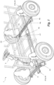
- said mechanism 4 and said axes 3 are both connected to the wheels 31, as shown in Fig. 1 , and are arranged substantially parallel to each other.
- the axes 3 is provided with a hub and with every means of the known art able to allow the rotation in more than one plane of said wheel 31, for example a rotation in a vertical plane for the motion and in a horizontal plane for the steering.
- the mechanism 4 can for example be composed of a kinematic mechanism connected to said wheels 31.
- An example of a preferred kinematic mechanism is shown in Fig. 1 , where said mechanism 4 comprises a plurality of components suitable for realizing an articulated parallelogram suitable for guaranteeing kinematic steering on said wheels 31.
- said mechanism 4 comprises a fixed rod 4a, two cranks and/or rocker arms 4b and a connecting rod 4c, said connecting rod connected at both ends to steering tie-rods 4d connected to the wheels.
- said steering mechanism 4 is placed in correspondence with each of said axes 3.
- the device 1 comprises a rudder 41 for controlling said kinematic steering mechanism 4.
- the rudder 41 is arranged transversely with respect to the axes 3, thus surmounting each of said axes as shown in Fig. 1 and can be connected to said mechanism 4.
- rudder 41 it is meant a rigid mechanical element, capable of transmitting a movement, that is, said command for example induced at one end of the same rudder 41.
- the shapes and materials of said rudder 41 can for example be further adapted to provide structural rigidity as will be clarified hereinafter in a preferred embodiment of the invention.
- connection between the rudder 41 and said mechanism 4 is such as to allow the transmission of motion from said rudder 41 to said wheels 31 by means of said mechanism 4.
- the transmission of motion can also take place in the opposite direction, from mechanism 4 to rudder 41, as will become clear in the following document.
- the rudder 41 is constrainable to said mechanism 4 in correspondence of each of said axes 3.
- the device 1 comprises a locking device 42 of said mechanism 4 which can be activated on each axis 3.
- the locking device 42 is able to make integral said rudder 41 by blocking the movement thereof, said mechanism 4 and said wheels 31, thus not allowing the lateral movement of the rudder 41 with respect to said axis 3 and therefore preventing the transmission of a steering command to the wheels 31 at said axis 3. Therefore, said locking device 42 is adapted to make the axis 3 on which the locking device 42 is active the fulcrum of rotation of said rudder 41 by rigidly connecting said mechanism 4 with said rudder 41.
- the locking mechanism 42 When the locking mechanism 42 is active, the lateral movement of the rudder 41 is therefore blocked by means of said steering mechanism 4, for example by directly or indirectly blocking the movement of the connecting rod 4c, preventing by transmitting the steering control from the rudder 41 to the wheels 31.
- the locking device 42 stops the rudder 41 in a substantially central position with respect to the two wheels 31 connected to the axis 3 on which said locking device 42 is activated. Therefore, the device 1 according to the present invention realizes through said drawbar 41 a variable steering ratio on each of said wheels 31 of said axes 3 of said vehicle 2.
- said vehicle comprises a front axis 3a and a rear axis 3b.
- the vehicle can generally comprise a plurality of axes defining in the same way a front axis 3a and a rear axis 3b.
- connection means 43 to control means 5 present on said vehicle 2 and accessible to a user.
- the connection means 43 can consist of purely mechanical, pneumo and/or electro-assisted connection means 43.
- said connection means 43 are purely mechanical suitable for imparting commands to said rudder 41.
- Said connection means 43 can connect said kinematic steering mechanism 4, which when rigidly connected to said rudder 41 allows its movement.
- the rudder 41 is therefore adapted to issue a different kinematic steering command for each axes 3, where said command is achieved through the geometric characteristics of the rudder 41 and/or as a function of the position of the locking device 42 with respect to the axes 3.
- the steering different kinematics between different axes is therefore implemented as a function of a quantity proportional to the steering, or to the angle and/or distance from a vertical, of said rudder 41 with respect to said axis 3.
- the kinematic steering of the wheels 31 of the same axis 3, which provides that two wheels 31 of the same axis 3 have different steering angles, said wheels 31 therefore receiving a single command from said rudder 41, is achieved by means of the steering mechanism 4, and therefore as a function of the kinematic mechanism used to transmit the command from the rudder 41 to the wheels 31.
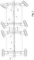
- FIG. 3 An example of what is described is shown in Fig. 3 through a kinematic diagram in which the device 1, by means of the rudder 41 locked by means of the device 42 on a rear axle 3b.
- the rudder 41 therefore, as a function of the distance from a vertical, imposes a substantially increasing steering angle as the distance of said axis 3 increases from the rear axis 3b on which the locking device 42 is present.
- said rudder 41 transmits a counter-steering command to the wheels 31 located on the axes 3 downstream of said locking 42.
- An example of this configuration is shown schematically in Fig. 4 .
- the present invention also relates to a modular kinematic steering device 1 adapted to be installed on a system 10 of modular vehicles.
- modular vehicles or rather by modules of said system, it is meant said vehicles 2 which are just described.
- Said modular vehicle system 10 comprising at least a first module 2' and a second module 2".
- modules when said modules are connected to form said system 10, they form a system 10 which is similar to a non-articulated vehicle, as will be clear from the explanation of the connection between said modules.
- Each module 2', 2" comprises a modular kinematic steering device 1.
- Said modular kinematic steering device 1 is a kinematic steering device 1 as just described in the present document, more preferably comprising a rudder 41 having a first distal end 41a and a second distal end 41b countered and/or counter-shaped in order to be rigidly connectable to each other.
- rigid connection in this document it is meant a connection that allows at least the transmission of a steering command through the combination of two or more rudders 41 of two or more modular vehicles 2', 2".
- said modular vehicle system 10 comprises at least a first module 2' and a second module 2", said first module 2' comprising at least a first rudder 41' having a first and a second distal ends 41a', 41b', said second module 2" comprising at least a second rudder 41" having a first and a second distal ends 41a", 41b", in which said distal ends 41 a', 41b" and/or 41 b' and 41 a" are countered and/or counter-shaped in order to be rigidly connectable to each other.
- said first module 2' comprises, in correspondence with the rear axis 3b, a distal end 41b' adapted to rigidly connect a distal end 41a" of said second module 2".
- Said ends 41a, 41b can be oriented in any way with respect to the axes 3 of the modular vehicle 2', 2".
- said rudders 41' and 41" each comprise a first distal end 41a and a second distal end 41b adapted to be connected by means of a coupling system 44.
- said coupling system 44 is present on each distal end 41a, 41b. Furthermore, components which concur to form the coupling system 44 may be present partly on one end and partly on the end that the latter connects.
- said coupling system 44 is a non-articulated coupling system.
- the coupling system 44 connects a plurality of rudders 41 in order to transmit a steering command in a non-articulated manner, for example without creating relative rotation angles between the two rudders 41', 41" of two vehicles 2', 2" coupled in order to obtain an inter-vehicular rudder and again without creating angles of relative rotation between the same vehicles 2', 2" connected to form said system 10.
- said coupling system 44 is adapted to activate and/or deactivate said locking device 42 of said kinematic steering mechanism 4 of an axis 3 by mechanical interference.
- said locking device 42 is electro-actuated.
- the operation of the device 1 previously described in structural terms is as follows.
- the device 1 applied to a 2-axle vehicle; in this case the selection of the axis on which locking device 42 of the rudder is active, it is limited since the rear axle 3b necessarily becomes the fulcrum of the rudder 41.
- said rudder 41 receives a steering control by means of control means 5 connected to the kinematic steering mechanism 4 housed near the front axis 3a.
- the control then rotates and/or integrally moves the mechanism 4, the wheels 31 and the rudder 41, the latter rotating around the fulcrum positioned by means of the device 42 on the rear axis 3b.
- the steering angle on the various vehicle axes is determined completely mechanically based on the amount of steering applied to the most advanced axle; the steering command is transmitted via an inter-vehicular rudder connected between the steering axes.
- the respective rudders are coupled rigidly and integrally, effectively creating a long inter-vehicular rudder whose operation is similar to that described in the system with only two axes.
- the system when equipped with more than two axles, can be made even more performing by ensuring a lower steering radius, by means of the locking device 42 which prevents an axis other than the first and the last from steering.
- the fixed axis through the locking system acts as the rotation fulcrum of the rudder-inter-vehicular so that the axes behind the fulcrum will counter-steer.
- the device 1 according to the invention achieves important advantages.
- the device 1 described here represents a very economical alternative to implement.
- the device 1 shown can be further hydraulically and electronically servo-assisted, but advantageously compared to prior art systems, in the event of a failure of the steering servo-assistance systems, the mechanical connection makes the system compliant with the ECE79 directives and guarantees the highest level of functional safety.
- the device 1 according to the present invention represents an alternative with a high degree of safety in case of failures.
- the steering ratio between the various axes is automatically coordinated by the geometry of the system without the need for electronic corrections.
Landscapes
- Engineering & Computer Science (AREA)
- Chemical & Material Sciences (AREA)
- Combustion & Propulsion (AREA)
- Transportation (AREA)
- Mechanical Engineering (AREA)
- Steering-Linkage Mechanisms And Four-Wheel Steering (AREA)
- Steering Control In Accordance With Driving Conditions (AREA)
Claims (8)
- Dispositif de direction cinématique modulaire (1) capable d'être installé sur au moins un premier module et un second module (2', 2") d'un système (10) de véhicules modulaires, chacun desdits modules (2', 2") comprenant au moins deux axes (3), ledit dispositif de direction cinématique modulaire comprenant- pour chaque axe (3), un mécanisme de direction cinématique (4) capable de déplacer des roues (31) reliées audit axe (3),- un gouvernail (41) pour contrôler ledit mécanisme de direction cinématique (4), disposé transversalement par rapport à l'axe (3), ledit gouvernail (41) pouvant être contraint audit mécanisme (4) de manière à permettre la transmission du mouvement dudit gouvernail (41) auxdites roues (31) au moyen dudit mécanisme (4), ledit gouvernail (41) définissant un rapport de direction variable par rapport à chacun desdits axes (3),
caractérisé en ce que le dispositif de direction cinématique modulaire comprend en outre- un dispositif de verrouillage (42) dudit mécanisme (4), capable de faire de l'un desdits axes (3) le pivot de rotation dudit gouvernail (41) en reliant rigidement ledit mécanisme (4) avec ledit gouvernail (41), et- dans lequel ledit premier module (2') comprend au moins un premier gouvernail (41') ayant des première et seconde extrémités distales (41a', 41b') et dans lequel ledit second module (2") comprend au moins un second gouvernail (41") ayant une première et une seconde extrémité distale (41a", 41b"), et dans lequel lesdites extrémités distales (41a', 41b", 41b', 41a") sont profilées et/ou contre-formées afin d'être rigidement reliées entre elles. - Dispositif (1) selon la revendication 1, dans lequel ledit gouvernail (41) comprend une première extrémité distale (41a) et une seconde extrémité distale (41b), capables d'être rigidement reliées entre elles afin de transmettre une commande de direction par un système d'accrochage (44).
- Dispositif (1) selon l'une quelconque des revendications précédentes, dans lequel ledit système d'accrochage (44) présent sur chaque extrémité distale (41a, 41b) est capable d'activer et/ou de désactiver par interférence mécanique un dispositif (42) de verrouillage dudit mécanisme de direction cinématique (4) d'un axe (3).
- Dispositif (1) selon l'une quelconque des revendications précédentes, dans lequel ledit dispositif de verrouillage (42) est actionné électriquement.
- Dispositif (1) selon l'une quelconque des revendications précédentes, dans lequel ledit système d'accrochage (44) est un système d'accrochage non articulé.
- Dispositif (1) selon l'une quelconque des revendications précédentes, dans lequel chacun desdits modules (2', 2") comprend au moins un axe avant (3a) et un axe arrière (3b), et dans lequel ledit axe avant (3a) dudit module (2', 2") comprend des moyens de connexion (43) à des moyens de commande (5) présents sur ledit véhicule (2) et accessibles à un utilisateur.
- Dispositif (1) selon l'une quelconque des revendications précédentes, dans lequel ledit mécanisme de direction cinématique (4) comprend une tige fixe (4a), deux manivelles et/ou bras oscillants (4b) et une bielle (4c), ladite bielle étant reliée aux deux extrémités à des barres de direction (4d) reliées aux roues (31).
- Dispositif (1) selon l'une quelconque des revendications précédentes, dans lequel ledit dispositif de verrouillage (42) dudit mécanisme (4), peut être activé sur chaque axe (3) et est capable de faire de l'axe (3) sur lequel ledit dispositif de verrouillage (42) est actif le pivot de rotation dudit gouvernail (41).
Applications Claiming Priority (2)
| Application Number | Priority Date | Filing Date | Title |
|---|---|---|---|
| IT202000027345 | 2020-11-16 | ||
| PCT/IB2021/057739 WO2022101698A1 (fr) | 2020-11-16 | 2021-08-24 | Dispositif de direction cinématique modulaire |
Publications (3)
| Publication Number | Publication Date |
|---|---|
| EP4244121A1 EP4244121A1 (fr) | 2023-09-20 |
| EP4244121B1 true EP4244121B1 (fr) | 2024-11-27 |
| EP4244121C0 EP4244121C0 (fr) | 2024-11-27 |
Family
ID=74858494
Family Applications (1)
| Application Number | Title | Priority Date | Filing Date |
|---|---|---|---|
| EP21770070.7A Active EP4244121B1 (fr) | 2020-11-16 | 2021-08-24 | Dispositif de direction cinématique modulaire |
Country Status (7)
| Country | Link |
|---|---|
| EP (1) | EP4244121B1 (fr) |
| JP (1) | JP7715323B2 (fr) |
| KR (1) | KR20230107581A (fr) |
| CN (1) | CN116568590B (fr) |
| ES (1) | ES3009935T3 (fr) |
| SA (1) | SA523440769B1 (fr) |
| WO (1) | WO2022101698A1 (fr) |
Family Cites Families (21)
| Publication number | Priority date | Publication date | Assignee | Title |
|---|---|---|---|---|
| GB578281A (en) * | 1942-09-21 | 1946-06-21 | Reginald Collis | Vehicle suspension and steering mechanism |
| DE1530548A1 (de) * | 1965-03-10 | 1969-06-19 | Daimler Benz Ag | Mehrradlenkung fuer Kraftfahrzeuge |
| FR1479023A (fr) * | 1966-05-09 | 1967-04-28 | Schwermaschb Kirow Veb | Dispositif de commande de direction de l'ensemble des roues de véhicules à quatre essieux, en particulier de grues pivotantes mobiles |
| JPS5334218A (en) * | 1976-09-11 | 1978-03-30 | Nissan Diesel Motor Co Ltd | Multi-shaft vehicle |
| JPS55109072U (fr) * | 1979-01-27 | 1980-07-30 | ||
| JPS59176164A (ja) * | 1983-03-23 | 1984-10-05 | Yanmar Agricult Equip Co Ltd | 前後輪ステアリング自在の四輪車におけるステアリング機構 |
| JPH0621818Y2 (ja) * | 1988-03-15 | 1994-06-08 | 日野自動車工業株式会社 | 後2軸車における後前軸車輪の操舵装置 |
| CZ278609B6 (en) * | 1992-11-30 | 1994-03-16 | Tatra Np | Device for steering wheels of at least three axes of a motor vehicle |
| DE4328238C1 (de) | 1993-08-19 | 1995-03-09 | Mannesmann Ag | Lenkung für ein Mehrachsfahrzeug, insbesondere Kranfahrzeug |
| DE19714485A1 (de) * | 1997-04-08 | 1998-10-15 | Kidde Ind Inc | Lenkung für ein mehrachsiges Fahrzeug |
| JPH11245839A (ja) * | 1998-03-05 | 1999-09-14 | Nippon Steel Corp | 多軸無人搬送車 |
| GB2341157B (en) * | 1998-09-04 | 2002-02-06 | Total Mobility Vehicles Ltd | An all-terrain vehicle |
| JP3759680B2 (ja) | 1998-12-25 | 2006-03-29 | 日野自動車株式会社 | 後輪操舵装置 |
| JP2000272519A (ja) | 1999-03-23 | 2000-10-03 | Yasuo Ajisaka | 手押し運搬台車 |
| US6619680B2 (en) * | 2001-10-30 | 2003-09-16 | Wellmaster Pipe And Supply Inc. | Agricultural wagon having all-wheel steering |
| CN102030035B (zh) * | 2010-12-06 | 2012-09-26 | 徐州重型机械有限公司 | 九轴汽车底盘起重机及其转向控制系统、方法 |
| DE102014106928B4 (de) * | 2014-05-16 | 2017-08-24 | Hamburg Innovation Gmbh | Gleisloser Routenzug |
| CN107685767B (zh) * | 2017-08-16 | 2019-07-05 | 吉林大学 | 多轴轮毂电机驱动车辆后轮线控转向驱动装置及转向方法 |
| US10220664B1 (en) * | 2017-10-02 | 2019-03-05 | Arden L. Brey | Trackless train with crosswise steering couplings between axles and cars |
| CN107933687B (zh) * | 2017-12-06 | 2023-07-28 | 西南交通大学 | 一种基于轮毂电机的管廊巡检小车全方位转向系统 |
| CN111578039A (zh) * | 2020-05-20 | 2020-08-25 | 河海大学常州校区 | 一种管道检测机器人 |
-
2021
- 2021-08-24 EP EP21770070.7A patent/EP4244121B1/fr active Active
- 2021-08-24 JP JP2023529018A patent/JP7715323B2/ja active Active
- 2021-08-24 WO PCT/IB2021/057739 patent/WO2022101698A1/fr not_active Ceased
- 2021-08-24 KR KR1020237016455A patent/KR20230107581A/ko active Pending
- 2021-08-24 CN CN202180077036.8A patent/CN116568590B/zh active Active
- 2021-08-24 ES ES21770070T patent/ES3009935T3/es active Active
-
2023
- 2023-05-14 SA SA523440769A patent/SA523440769B1/ar unknown
Also Published As
| Publication number | Publication date |
|---|---|
| US20240001990A1 (en) | 2024-01-04 |
| WO2022101698A1 (fr) | 2022-05-19 |
| ES3009935T3 (en) | 2025-03-31 |
| KR20230107581A (ko) | 2023-07-17 |
| EP4244121C0 (fr) | 2024-11-27 |
| CN116568590A (zh) | 2023-08-08 |
| SA523440769B1 (ar) | 2024-07-28 |
| EP4244121A1 (fr) | 2023-09-20 |
| CN116568590B (zh) | 2026-02-06 |
| JP2023551412A (ja) | 2023-12-08 |
| JP7715323B2 (ja) | 2025-07-30 |
Similar Documents
| Publication | Publication Date | Title |
|---|---|---|
| US6450523B1 (en) | Steering method for a trailing section of an articulated vehicle | |
| US6164406A (en) | Multiple-axle steering system for agricultural harvesting machines | |
| US8256780B2 (en) | Vehicle steering device | |
| EP0233850B1 (fr) | Dispositif d'amortissement contrôlé des mouvements de pivotement d'un bus articulé | |
| EP2404808B1 (fr) | Véhicule automobile doté d'une fusée d'essieu ou d'une direction articulée | |
| DE19806655A1 (de) | Elektronische Rangierhilfe für einen Lastwagen mit Anhänger | |
| US8910741B2 (en) | Steering device for tractor | |
| SE1851476A1 (en) | A power assisted steering system arrangement | |
| EP1466813B1 (fr) | Axe de dolly avec train de roues orientables | |
| EP2767455B1 (fr) | Module hydro-électrique pour la direction d'essieux avant et arrière | |
| US5975548A (en) | Vehicle with pivoting mudguard | |
| US4798393A (en) | Rider-controlled working machine with four-wheel steering system | |
| EP3533688B1 (fr) | Système de direction active destiné à être utilisé dans une machine de levage, machine de levage | |
| US12630220B2 (en) | Modular kinematic steering device | |
| US20240001990A1 (en) | Modular kinematic steering device | |
| EP0930218B1 (fr) | Véhicule de transport lourd à moteur avec au moins deux essieux avant à roues directrices | |
| CA2298048A1 (fr) | Direction pour moyen de transport | |
| WO2004098981A1 (fr) | Remorque orientable | |
| US20250108868A1 (en) | Trailer steering system | |
| US20220135126A1 (en) | Trailer tracking control | |
| EP0845403A2 (fr) | Direction assistée pour des roues auto-orientable d'un ou plusieurs essieux d'un véhicule à moteur comme un camion, une remorque et une semi-remorque, pour diriger le véhicule dans la marche arrière | |
| NO155234B (no) | Anordning ved midjestyrte kjoeretoey. | |
| EP4244106B1 (fr) | Système de véhicules modulaires comprenant un dispositif de freinage modulaire | |
| US3338329A (en) | Steering | |
| AU2021203310A1 (en) | Improved Articulated Vehicle |
Legal Events
| Date | Code | Title | Description |
|---|---|---|---|
| STAA | Information on the status of an ep patent application or granted ep patent |
Free format text: STATUS: UNKNOWN |
|
| STAA | Information on the status of an ep patent application or granted ep patent |
Free format text: STATUS: THE INTERNATIONAL PUBLICATION HAS BEEN MADE |
|
| PUAI | Public reference made under article 153(3) epc to a published international application that has entered the european phase |
Free format text: ORIGINAL CODE: 0009012 |
|
| STAA | Information on the status of an ep patent application or granted ep patent |
Free format text: STATUS: REQUEST FOR EXAMINATION WAS MADE |
|
| 17P | Request for examination filed |
Effective date: 20230519 |
|
| AK | Designated contracting states |
Kind code of ref document: A1 Designated state(s): AL AT BE BG CH CY CZ DE DK EE ES FI FR GB GR HR HU IE IS IT LI LT LU LV MC MK MT NL NO PL PT RO RS SE SI SK SM TR |
|
| DAV | Request for validation of the european patent (deleted) | ||
| DAX | Request for extension of the european patent (deleted) | ||
| GRAP | Despatch of communication of intention to grant a patent |
Free format text: ORIGINAL CODE: EPIDOSNIGR1 |
|
| STAA | Information on the status of an ep patent application or granted ep patent |
Free format text: STATUS: GRANT OF PATENT IS INTENDED |
|
| INTG | Intention to grant announced |
Effective date: 20240704 |
|
| GRAS | Grant fee paid |
Free format text: ORIGINAL CODE: EPIDOSNIGR3 |
|
| GRAA | (expected) grant |
Free format text: ORIGINAL CODE: 0009210 |
|
| STAA | Information on the status of an ep patent application or granted ep patent |
Free format text: STATUS: THE PATENT HAS BEEN GRANTED |
|
| AK | Designated contracting states |
Kind code of ref document: B1 Designated state(s): AL AT BE BG CH CY CZ DE DK EE ES FI FR GB GR HR HU IE IS IT LI LT LU LV MC MK MT NL NO PL PT RO RS SE SI SK SM TR |
|
| REG | Reference to a national code |
Ref country code: GB Ref legal event code: FG4D |
|
| REG | Reference to a national code |
Ref country code: CH Ref legal event code: EP |
|
| REG | Reference to a national code |
Ref country code: DE Ref legal event code: R096 Ref document number: 602021022502 Country of ref document: DE |
|
| REG | Reference to a national code |
Ref country code: IE Ref legal event code: FG4D |
|
| U01 | Request for unitary effect filed |
Effective date: 20241219 |
|
| U07 | Unitary effect registered |
Designated state(s): AT BE BG DE DK EE FI FR IT LT LU LV MT NL PT RO SE SI Effective date: 20250113 |
|
| REG | Reference to a national code |
Ref country code: ES Ref legal event code: FG2A Ref document number: 3009935 Country of ref document: ES Kind code of ref document: T3 Effective date: 20250331 |
|
| PG25 | Lapsed in a contracting state [announced via postgrant information from national office to epo] |
Ref country code: IS Free format text: LAPSE BECAUSE OF FAILURE TO SUBMIT A TRANSLATION OF THE DESCRIPTION OR TO PAY THE FEE WITHIN THE PRESCRIBED TIME-LIMIT Effective date: 20250327 Ref country code: HR Free format text: LAPSE BECAUSE OF FAILURE TO SUBMIT A TRANSLATION OF THE DESCRIPTION OR TO PAY THE FEE WITHIN THE PRESCRIBED TIME-LIMIT Effective date: 20241127 |
|
| PG25 | Lapsed in a contracting state [announced via postgrant information from national office to epo] |
Ref country code: GR Free format text: LAPSE BECAUSE OF FAILURE TO SUBMIT A TRANSLATION OF THE DESCRIPTION OR TO PAY THE FEE WITHIN THE PRESCRIBED TIME-LIMIT Effective date: 20250228 |
|
| PG25 | Lapsed in a contracting state [announced via postgrant information from national office to epo] |
Ref country code: PL Free format text: LAPSE BECAUSE OF FAILURE TO SUBMIT A TRANSLATION OF THE DESCRIPTION OR TO PAY THE FEE WITHIN THE PRESCRIBED TIME-LIMIT Effective date: 20241127 |
|
| PG25 | Lapsed in a contracting state [announced via postgrant information from national office to epo] |
Ref country code: RS Free format text: LAPSE BECAUSE OF FAILURE TO SUBMIT A TRANSLATION OF THE DESCRIPTION OR TO PAY THE FEE WITHIN THE PRESCRIBED TIME-LIMIT Effective date: 20250227 |
|
| PG25 | Lapsed in a contracting state [announced via postgrant information from national office to epo] |
Ref country code: SM Free format text: LAPSE BECAUSE OF FAILURE TO SUBMIT A TRANSLATION OF THE DESCRIPTION OR TO PAY THE FEE WITHIN THE PRESCRIBED TIME-LIMIT Effective date: 20241127 |
|
| U20 | Renewal fee for the european patent with unitary effect paid |
Year of fee payment: 5 Effective date: 20250606 |
|
| PG25 | Lapsed in a contracting state [announced via postgrant information from national office to epo] |
Ref country code: SK Free format text: LAPSE BECAUSE OF FAILURE TO SUBMIT A TRANSLATION OF THE DESCRIPTION OR TO PAY THE FEE WITHIN THE PRESCRIBED TIME-LIMIT Effective date: 20241127 |
|
| PG25 | Lapsed in a contracting state [announced via postgrant information from national office to epo] |
Ref country code: CZ Free format text: LAPSE BECAUSE OF FAILURE TO SUBMIT A TRANSLATION OF THE DESCRIPTION OR TO PAY THE FEE WITHIN THE PRESCRIBED TIME-LIMIT Effective date: 20241127 |
|
| PLBE | No opposition filed within time limit |
Free format text: ORIGINAL CODE: 0009261 |
|
| STAA | Information on the status of an ep patent application or granted ep patent |
Free format text: STATUS: NO OPPOSITION FILED WITHIN TIME LIMIT |
|
| REG | Reference to a national code |
Ref country code: CH Ref legal event code: L10 Free format text: ST27 STATUS EVENT CODE: U-0-0-L10-L00 (AS PROVIDED BY THE NATIONAL OFFICE) Effective date: 20251008 |
|
| PGFP | Annual fee paid to national office [announced via postgrant information from national office to epo] |
Ref country code: ES Payment date: 20250917 Year of fee payment: 5 |
|
| PGFP | Annual fee paid to national office [announced via postgrant information from national office to epo] |
Ref country code: NO Payment date: 20250820 Year of fee payment: 5 |
|
| PGFP | Annual fee paid to national office [announced via postgrant information from national office to epo] |
Ref country code: TR Payment date: 20250814 Year of fee payment: 5 |
|
| PGFP | Annual fee paid to national office [announced via postgrant information from national office to epo] |
Ref country code: GB Payment date: 20250822 Year of fee payment: 5 |
|
| 26N | No opposition filed |
Effective date: 20250828 |
|
| REG | Reference to a national code |
Ref country code: CH Ref legal event code: H13 Free format text: ST27 STATUS EVENT CODE: U-0-0-H10-H13 (AS PROVIDED BY THE NATIONAL OFFICE) Effective date: 20260324 |
|
| PG25 | Lapsed in a contracting state [announced via postgrant information from national office to epo] |
Ref country code: MC Free format text: LAPSE BECAUSE OF FAILURE TO SUBMIT A TRANSLATION OF THE DESCRIPTION OR TO PAY THE FEE WITHIN THE PRESCRIBED TIME-LIMIT Effective date: 20241127 |
|
| PG25 | Lapsed in a contracting state [announced via postgrant information from national office to epo] |
Ref country code: CH Free format text: LAPSE BECAUSE OF NON-PAYMENT OF DUE FEES Effective date: 20250831 |