EP4244331B1 - Mehrkammer-nitrifikationsreaktor zur fugate-verarbeitung und verfahren zu dessen inbetriebnahme in vollmassstabbetrieb - Google Patents
Mehrkammer-nitrifikationsreaktor zur fugate-verarbeitung und verfahren zu dessen inbetriebnahme in vollmassstabbetrieb Download PDFInfo
- Publication number
- EP4244331B1 EP4244331B1 EP21856899.6A EP21856899A EP4244331B1 EP 4244331 B1 EP4244331 B1 EP 4244331B1 EP 21856899 A EP21856899 A EP 21856899A EP 4244331 B1 EP4244331 B1 EP 4244331B1
- Authority
- EP
- European Patent Office
- Prior art keywords
- chamber
- fugate
- tank
- volume
- reactor
- Prior art date
- Legal status (The legal status is an assumption and is not a legal conclusion. Google has not performed a legal analysis and makes no representation as to the accuracy of the status listed.)
- Active
Links
Images
Classifications
-
- C—CHEMISTRY; METALLURGY
- C12—BIOCHEMISTRY; BEER; SPIRITS; WINE; VINEGAR; MICROBIOLOGY; ENZYMOLOGY; MUTATION OR GENETIC ENGINEERING
- C12M—APPARATUS FOR ENZYMOLOGY OR MICROBIOLOGY; APPARATUS FOR CULTURING MICROORGANISMS FOR PRODUCING BIOMASS, FOR GROWING CELLS OR FOR OBTAINING FERMENTATION OR METABOLIC PRODUCTS, i.e. BIOREACTORS OR FERMENTERS
- C12M23/00—Constructional details, e.g. recesses, hinges
- C12M23/34—Internal compartments or partitions
-
- C—CHEMISTRY; METALLURGY
- C12—BIOCHEMISTRY; BEER; SPIRITS; WINE; VINEGAR; MICROBIOLOGY; ENZYMOLOGY; MUTATION OR GENETIC ENGINEERING
- C12M—APPARATUS FOR ENZYMOLOGY OR MICROBIOLOGY; APPARATUS FOR CULTURING MICROORGANISMS FOR PRODUCING BIOMASS, FOR GROWING CELLS OR FOR OBTAINING FERMENTATION OR METABOLIC PRODUCTS, i.e. BIOREACTORS OR FERMENTERS
- C12M23/00—Constructional details, e.g. recesses, hinges
- C12M23/58—Reaction vessels connected in series or in parallel
-
- C—CHEMISTRY; METALLURGY
- C12—BIOCHEMISTRY; BEER; SPIRITS; WINE; VINEGAR; MICROBIOLOGY; ENZYMOLOGY; MUTATION OR GENETIC ENGINEERING
- C12M—APPARATUS FOR ENZYMOLOGY OR MICROBIOLOGY; APPARATUS FOR CULTURING MICROORGANISMS FOR PRODUCING BIOMASS, FOR GROWING CELLS OR FOR OBTAINING FERMENTATION OR METABOLIC PRODUCTS, i.e. BIOREACTORS OR FERMENTERS
- C12M29/00—Means for introduction, extraction or recirculation of materials, e.g. pumps
- C12M29/06—Nozzles; Sprayers; Spargers; Diffusers
-
- C—CHEMISTRY; METALLURGY
- C12—BIOCHEMISTRY; BEER; SPIRITS; WINE; VINEGAR; MICROBIOLOGY; ENZYMOLOGY; MUTATION OR GENETIC ENGINEERING
- C12M—APPARATUS FOR ENZYMOLOGY OR MICROBIOLOGY; APPARATUS FOR CULTURING MICROORGANISMS FOR PRODUCING BIOMASS, FOR GROWING CELLS OR FOR OBTAINING FERMENTATION OR METABOLIC PRODUCTS, i.e. BIOREACTORS OR FERMENTERS
- C12M41/00—Means for regulation, monitoring, measurement or control, e.g. flow regulation
- C12M41/02—Means for regulation, monitoring, measurement or control, e.g. flow regulation of foam
-
- C—CHEMISTRY; METALLURGY
- C12—BIOCHEMISTRY; BEER; SPIRITS; WINE; VINEGAR; MICROBIOLOGY; ENZYMOLOGY; MUTATION OR GENETIC ENGINEERING
- C12M—APPARATUS FOR ENZYMOLOGY OR MICROBIOLOGY; APPARATUS FOR CULTURING MICROORGANISMS FOR PRODUCING BIOMASS, FOR GROWING CELLS OR FOR OBTAINING FERMENTATION OR METABOLIC PRODUCTS, i.e. BIOREACTORS OR FERMENTERS
- C12M41/00—Means for regulation, monitoring, measurement or control, e.g. flow regulation
- C12M41/26—Means for regulation, monitoring, measurement or control, e.g. flow regulation of pH
-
- C—CHEMISTRY; METALLURGY
- C12—BIOCHEMISTRY; BEER; SPIRITS; WINE; VINEGAR; MICROBIOLOGY; ENZYMOLOGY; MUTATION OR GENETIC ENGINEERING
- C12M—APPARATUS FOR ENZYMOLOGY OR MICROBIOLOGY; APPARATUS FOR CULTURING MICROORGANISMS FOR PRODUCING BIOMASS, FOR GROWING CELLS OR FOR OBTAINING FERMENTATION OR METABOLIC PRODUCTS, i.e. BIOREACTORS OR FERMENTERS
- C12M41/00—Means for regulation, monitoring, measurement or control, e.g. flow regulation
- C12M41/30—Means for regulation, monitoring, measurement or control, e.g. flow regulation of concentration
- C12M41/34—Means for regulation, monitoring, measurement or control, e.g. flow regulation of concentration of gas
Definitions
- the present invention relates to a unique multi-chamber design of a nitrification reactor capable of processing, within a given agricultural biogas plant, the entire production of fugate, or a required part thereof.
- the fugate is produced in buildings of biogas plants equipped with a digestate separator. It represents the liquid fraction of the digestate, while during the separation it is formed together with the so-called separate, which is the solid fraction of the digestate. It has been shown that the treatment of fugate by the biological nitrification process can lead to the elimination of a number of problems, in particular to the prevention of nitrogen losses during the handling of fugate.
- the fugate is currently usually applied directly to agricultural land as a source of nutrients for plant nutrition. It contains mainly nitrogen and potassium compounds, the content of other nutrients, including phosphorus, can also be significant. However, the big problem is that nitrogen, as essentially the most valuable nutrient contained in fugate, occurs in a relatively unstable form there. Most of the nitrogen in the fugate is present in the form of total ammonia nitrogen (TAN, the sum of N-NH 4 + and N-NH 3 ). Depending on the environmental conditions, TAN occurs in two dissociation forms, as N-NH 4 + and N-NH 3 . The representation of these two forms depends mainly on the pH value and the temperature. There is a relatively high proportion of N-NH 3 in the fugate environment, which is volatile.
- CN106520610A relates to production technology of high-density composite nitrobacterium inoculant, and high-density fermentation batch culture fermentation tank system of nitrobacteria.
- the disclosed high-density batch culture production technology of a nitrobacterium inoculant for degrading ammonia nitrogen in water comprises the steps of magnetic nano-powder preparation, nitrobacterium seed liquid culture, magnetically carried nitrobacterium immobilization, batch fermentation culture, flocculation mixed precipitate magnetic separation, freeze drying and preparation compounding.
- the production technology improves the effective cell density of a nitrobacterium preparation, allows a flocculating agent and a stimulant to be compounded while preparing the nitrobacteria inoculant, and the nitrobacterium inoculant can be used in water restoration, can improve the transparence of water, and guarantees the sufficient nitrobacterium cell density required by water restoration and adaptability to new environment.
- the high-density fermentation batch culture fermentation tank system of nitrobacteria used for the technology, contains one ventilated mixing tank with a feeding pump, discharging pump, flocculant dosing tube, pH adjustment means, a dosing tube for defoaming agent, and a stirrer. Dissolved oxygen and pH are also measured during the process.
- TAN is a substrate for the organisms of the first phase of nitrification - ammonia oxidizing bacteria (AOB), it has an inhibitory effect on them at higher concentrations.
- AOB nitrification - ammonia oxidizing bacteria
- NOB nitrification - nitrite oxidizing bacteria
- the object of the present invention is a nitrification reactor for fugate processing, which comprises:
- the pH adjusting agent for the neutralization station is preferably an aqueous solution of NaOH or Ca(OH) 2 , which is suitable for adjusting the pH of the processed fugate, however, other alternative basic agents can be used for pH adjustment, especially aqueous solutions of alkali metal or alkaline earth metal hydroxides.
- the tank of the nitrification reactor is preferably made of concrete or plastic and preferably has a volume in the range of from 30 to 500 m 3 .
- the nitrification reactor tank is divided into three separate chambers of unequal volume.
- the chambers are preferably located horizontally next to each other (preferably the nitrification reactor tank is divided by concrete, plastic or other partitions into three separate chambers situated next to each other) and each chamber is separate (the nitrification process takes place in each chamber independently of the other chambers).
- Each chamber has a separate inlet for raw fugate and an outlet for nitrified fugate, its own air distribution and probes for measuring pH and O 2 .
- the fugate does not pass from one chamber to another; however, in the event of an 'accident' or problem, nitrifying biomass from one chamber can be used to ⁇ revive' nitrifying bacteria in the chamber in which the problem occurred.
- Each chamber works in conditions approaching the so-called completely stirred tank reactor (CSTR), i.e. in the whole volume of the chamber there is a mixture with practically identical properties.
- CSTR completely stirred tank reactor
- the stirring of the content of the chamber is ensured by air which bubbles in the entire volume of the chamber.
- the inlet for raw fugate and the outlet for nitrified fugate can be located above the air distribution device at any height of the chamber.
- the tank or each of its chambers comprises a separate inlet for nitrifying biomass. This makes it possible to continuously add to each chamber nitrifying biomass produced, for example, in the nitrifying biomass cultivation device described below.
- the optimum volume of the nitrification reactor for a particular biogas plant is preferably determined based on the concentration of TAN in raw fugate to be nitrified and the target volume nitrogen loading rate of the reactor.
- the target nitrogen loading rate is determined in advance within the laboratory simulation of the whole nitrification process.
- a small laboratory reactor volume approx. 1 to 5 L
- the nitrification process is initiated and operated analogously to the described reactor according to the present invention (nitrogen loading rate and pH at the start of nitrification depends on the inoculum of nitrifying microorganisms used and the source of the fugate - its chemical composition).
- activated sludge from a municipal wastewater treatment plant is used for inoculation.
- Gradual regulation of conditions, especially fugate flow rate determines what loading rate the system is able to process under the given conditions (i.e. nitrogen loading rate at which nitrifying microorganisms are effectively cultivated where no risk of overloading of the system and from it resulting deterioration of the function of the reactor could be expected). Too high fugate flow rate and/or too low pH in the reactor would lead to undesired disruption of the nitrifying microorganism cultivation process.
- the rate of dosing of the fugate into the nitrification reactor is determined by the required nitrogen loading rate of the device. It depends on the target nitrogen loading rate and the concentration of TAN in the processed fugate.
- the nitrogen loading rate is calculated multiplying the nitrogen concentration in the fugate and the fugate flow rate, divided by the tank volume.
- the target nitrogen loading rate is preferably in the range of from 0.3 to 0.8 kg/(m 3 ⁇ ⁇ d); the target operating pH value is then in the range of from 4.5 to 6.
- the nitrification reactor tank is divided into 3 chambers (S 1, S2 and S3), the volume of the first chamber S 1 is smaller than the volume of the second chamber S2, which is smaller than the volume of the third chamber S3, the volume of the first chamber S 1 representing 5 to 10 per cent of the total reactor tank volume, the volume of the second chamber S2 representing 20 to 30 per cent of the total reactor tank volume and the volume of the third chamber S3 representing 60 to 75 per cent of the total volume of the nitrification reactor tank.
- S1, S2 and S3 occupy 8.5, 25.5 and 66 per cent of the total volume of the nitrification reactor tank.
- the source of compressed air is selected from the group comprising a blower and a compressor.
- the air distribution device is preferably located at the bottom of each chamber of the reactor tank, more preferably over the entire area of the tank chamber bottom, and ensures homogenization of the suspension throughout its volume and prevents its sedimentation.
- the air distribution device can be, for example, a perforated material, a perforated tube or nozzles (e.g. suitably perforated hose, preferably made of flexible material, the openings of which close themselves at rest, perforated or porous surface, etc.).
- the transport of the fugate to the nitrification reactor tank and the outflow of the nitrified fugate from the nitrification reactor tank are preferably provided by pumps used in wastewater treatment. These are mainly sludge, submersible, self-priming, centrifugal, horizontal/vertical or spiral body pumps.
- the pH value is adjusted by adding a pH adjusting agent by a pump from the tank.
- the pH adjusting agent may be selected from the group comprising aqueous alkali metal hydroxide solutions, CaCO 3 , Ca(OH) 2 .
- a source of compressed air is also connected to the measuring and control unit by feedback, which ensures a smooth and automatic control of the aeration intensity depending on the measured value of the O 2 concentration in the fugate.
- each of the tank chambers comprises an inlet for defoamer connected to the container for defoamer. Through this inlet, the defoamer is dosed from the container for defoamer to the individual chambers of the reactor tank. More preferably, the container for defoamer is connected to a dispenser which is connected to the measuring and control unit by feedback. This makes it possible to automate the defoamer dosing into the tank.
- Another object of the present invention is a method of start-up (putting into operation) of a multi-chamber nitrification reactor according to the present invention.
- First, laboratory tests determine the target nitrogen loading rate of nitrification reactor of the given biogas plant and the operating pH value for the nitrification reactor. These laboratory tests are performed before the actual installation of the nitrification reactor according to the present invention in the area of the given biogas plant.
- the process is simulated in the laboratory in a small reactor with a volume of 1 to 5 L.
- the whole nitrification process is simulated, the conditions are varied (the fugate flow rate and thus nitrogen loading rate, and other parameters - pH, O 2 concentration) and the efficiency of the nitrification process is checked (the proportion of nitrified nitrogen in the effluent fugate is determined).
- the conditions target nitrogen loading rate and operating pH value
- ideal for the fugate from the given biogas plant are selected (i.e. those conditions under which the proportion of nitrified nitrogen in the effluent fugate is maximum).
- the cultivation of nitrifying biomass decreases or stops, and thus the production of nitrified nitrogen decreases.
- the target loading rate of the nitrification reactor depends not only on the concentration of TAN in raw fugate, but also on the current fugate flow rate and the nitrification reactor volume. It is given in kg of TAN entering the 1 m 3 tank in one day.
- the laboratory simulation defines the combination of N-ammon concentration and fugate flow rate that the reactor of a given volume 'manages' .
- the target nitrogen loading rate of the system and the average TAN concentration in the fugate will then make it possible to determine the reactor volume for fugate processing so that the required hydraulic retention time for the fugate in the reactor is achieved.
- the reactor volume is calculated according to equation (1) from the 'target nitrogen loading rate', the daily production of fugate (i.e. the daily amount of raw fugate processed) and the concentration of TAN in raw fugate.
- V c ⁇ Q/Bv
- V is the volume of the nitrification reactor (m 3 ); Bv is the target nitrogen loading rate (kg/(m 3 ⁇ d)), determined by the laboratory simulation of the nitrification process described above; c is the concentration of TAN in raw fugate (kg/m 3 ); Q is the target flow rate of fugate through the reactor (or daily production of raw fugate within a given biogas plant, respectively) (m 3 /d).
- the nitrification reactor according to the present invention is constructed, the tank of which is divided into at least three separate chambers of unequal size.
- the volume of the first chamber (S 1) is from 5 to 10 per cent of the total tank volume; the volume of the second chamber (S2) is from 20 to 30 per cent of the total tank volume; and the volume of the third chamber (S3) is from 60 to 75 per cent of the total volume of the nitrification reactor tank.
- the volume of the first chamber (S1) is 8.5 per cent of the total tank volume; the volume of the second chamber (S2) is 25.5 per cent of the total tank volume; and the volume of the third chamber (S3) is 66 per cent of the total volume of the nitrification reactor tank.
- a nitrifying culture of microorganisms capable of processing the fugate is placed into the first chamber S 1 of the nitrification reactor tank, which has a volume corresponding to the value determined above.
- the nitrifying culture of microorganisms (capable of processing the fugate) is placed into the first chamber S 1 in an amount of 10 to 50 per cent of the volume of the first chamber S 1 of the tank.
- the nitrifying biomass cultivated in the nitrifying biomass cultivating device described below is used, which is placed into the first chamber S 1 in an amount of 10 to 50 per cent of the volume of the first chamber S 1 of the tank. Furthermore, the raw fugate produced by the given biogas plant is gradually fed into the first chamber S1 at a daily inflow rate of from 0.25 to 5 per cent of the total daily fugate production of the given biogas plant.
- the same amount of nitrifying culture of microorganisms preferably produced by the nitrifying biomass cultivation device described below, is dosed into S1 at the same time.
- the effluent from the nitrifying biomass cultivation device is also dosed into S 1 in a constant amount.
- the nitrifying culture of microorganisms supplied to the mixture with the fugate, preferably from the nitrifying biomass cultivation device described below, gradually propagates (the fugate represents a substrate for the nitrifying microorganisms).
- the addition of further raw fugate creates a new nitrifying biomass that needs a new fresh substrate - in this case further raw fugate. Therefore, it is necessary to gradually increase the fugate dosage.
- the pH value is maintained at all times at the operating pH value specified above.
- the pH value is in the range of from 4.5 to 6.
- the gradual increase in the raw fugate dosage is carried out in five-day periods, so that five days after the inoculation, the volume of fugate in the first chamber S1 corresponds to 11 to 75 per cent of the total volume of S1.
- the raw fugate dosage is constant for five days and is given by equation (2), so the volume of the mixture inside the chamber S1 increases according to the dosing rate of the raw fugate. After five days of constant rate of dosing raw fugate into chamber S1, the dosing rate increases (calculated from equation (2) based on the current volume of the mixture in the chamber at the end of the previous five-day period), and for the following five days the raw fugate is dosed to S1 at this higher flow rate.
- the increase of the dosing rate continues in five-day cycles so that the target nitrogen loading rate is not exceeded, until the chamber S1 is completely filled with the mixture of fugate and nitrifying biomass.
- the purpose of this gradual increase in dosing is to speed up the nitrification reactor start-up process. If the raw fugate were dosed at the original rate throughout the reactor start-up, this start-up would take a longer time.
- the third chamber S3 When the third chamber S3 is filled up, a part of the mixture from S3 is transferred to S1 and S2 so that the volume of liquid in all chambers represents the same part of their total capacity (under given conditions from 60 to 75 per cent of the capacity of each chamber). From this point on, the raw fugate is fed to the individual chambers in an amount corresponding to their share in the total volume of the operating reactor. Thus, if the chamber S1 occupies from 5 to 10 per cent of the volume of the entire nitrification reactor tank, then from 5 to 10 per cent of the volume of the total raw fugate to be processed will be fed into it.
- the chamber S2 occupies from 20 to 30 per cent of the volume of the entire nitrification reactor tank, then from 20 to 30 per cent of the volume of the total raw fugate to be processed will be fed into it, and if S3 occupies from 60 to 75 per cent of the volume of the entire nitrification reactor tank, then about from 60 to 75 per cent of the total amount of raw fugate fed to the system will be fed to it.
- the dosing of raw fugate will continue to increase in five-day periods, until it is gradually increased to a value corresponding to the total daily fugate production of the given biogas plant, or its required part. This will achieve the processing of the required amount of fugate produced by the given biogas plant and the nitrification reactor start-up will be considered as completed (the reactor will be ready for full scale operation).
- the nitrified fugate leaving the reactor can be used for application to the soil as fertilizer.
- the cultivated nitrifying biomass is added to enrich the system with nitrifying bacteria throughout the process of start-up of the full scale reactor After all the chambers of the nitrification reactor have been filled up, this addition of nitrifying bacteria can be stopped, because the amount of nitrifying organisms coming with it to the full scale reactor is already negligible in terms of the total volume of the fully operating reactor.
- a nitrifying biomass cultivation device can be used to inoculate the nitrification reactor for fugate processing.
- the necessary nitrifying culture of microorganisms capable of processing the fugate under the conditions defined in the previously performed laboratory experiments is obtained.
- Said nitrifying biomass cultivation device comprises a plastic tank with a volume in the range of from 0.5 to 2 m 3 , which comprises at least one aeration element connected to a source of compressed air; an inlet for biomass located in the lower third of the tank height; an outlet for nitrified biomass, preferably located in the upper third of the tank height; a pH measuring probe and an O 2 concentration measuring probe located inside the tank and connected to the measuring and control unit; and an inlet for pH adjusting agent connected to a pump connected to the pH adjusting agent tank, wherein the pump and the aeration element are connected to the measuring and control unit by feedback.
- the device may further comprise an inlet for defoamer connected to a container for defoamer.
- the required nitrifying culture of microorganisms capable of processing the fugate is obtained in the described device as follows: the tank of the device is first filled with inoculum, for example activated sludge collected in the biological stage of a municipal wastewater treatment plant can be used. The dosing of the fugate into the tank of the device is then started through the substrate inlet, preferably by means of a peristaltic pump. The mixture of the inoculum and fugate is aerated in the tank by means of at least one aeration element connected to a source of compressed air. The dosing and aeration rate is regulated by a measuring and control unit depending on the pH and O 2 concentration in the tank and on the value of the target nitrogen loading rate.
- inoculum for example activated sludge collected in the biological stage of a municipal wastewater treatment plant can be used.
- the dosing of the fugate into the tank of the device is then started through the substrate inlet, preferably by means of a peristaltic pump.
- the pH is regulated by dosing the pH adjusting agent into the tank.
- the target nitrogen loading rate is determined in a laboratory apparatus according to the procedure described above, preferably its value is in the range of from 0.3 to 0.8 kg/(m 3 ⁇ d); the target operating pH value is then in the range of from 4.5 to 6.
- the target nitrogen loading rate is 0.5 kg/(m 3 ⁇ d) and the target operating pH value is 5.
- the substrate fugate
- the substrate is dosed into the tank of the device with an intensity corresponding to 10 per cent of the target nitrogen loading rate value under conditions with pH regulated to the value of 7.
- the system load will increase to 20 per cent of the target nitrogen loading rate value for 10 days and gradually to 40, 60 and 80 per cent of the target nitrogen loading rate value over the next ten-day periods.
- the nitrifying biomass cultivation device will reach its target performance after 50 days.
- the operating pH value decreases.
- the effluent from the tank of the device can be used to inoculate a fully operating nitrification reactor according to the present invention to nitrify the fugate, which will be operated under analogous conditions.
- the effluent from the nitrifying biomass cultivation device can be connected directly to the individual chambers S1, S2 and S3 of the nitrification reactor or it can be collected in suitable tanks (e.g. in IBC containers with a volume of 1 m 3 ). It is recommended to ensure aeration of IBC containers to achieve an oxygen concentration of at least 1 mg/L in said container.
- Further object of the present invention is the use of said nitrification reactor to nitrify raw fugate from biogas plants.
- BGP biogas plant
- the target nitrogen loading rate and the target pH are determined by laboratory simulation of the nitrification process in a small laboratory nitrification reactor (volume of approx. 1 to 5 L).
- the nitrification process is initiated by placing an inoculum (e.g. activated sludge from a municipal wastewater treatment plant) in the laboratory nitrification reactor.
- the inoculum fills the entire reactor volume.
- the continuous dosing of the fugate into the nitrification reactor is started with a gradual increase of the fugate flow rate, resp. the reactor nitrogen loading rate.
- the nitrogen loading rate can be calculated as the product of the nitrogen concentration in the substrate (fugate) multiplied by the substrate (fugate) flow rate divided by the tank volume.
- the usual values of the target nitrogen loading rate for fugate are in the range of from 0.3 to 0.8 kg/(m 3 ⁇ d), and the target operating pH value is in the range of from 4.5 to 6.
- the pH value is continuously monitored in the reactor using a suitable measuring and control system.
- the fugate is dosed in an amount corresponding to the nitrogen loading rate of 0.05 kg/(m 3 ⁇ d).
- the operating pH value which is adjusted by dosing 10% NaOH solution.
- the dosing of this solution compensates for the decrease in pH caused by the release of H + ions during nitrification.
- the dosing intensity of the NaOH solution is gradually reduced.
- the purpose of this phase of reactor operation is to determine the target pH value. For the first 10 days, the operating pH is adjusted to 7.
- the controlled pH reduction is terminated in the phase when the real pH value measured in the reactor is higher than the value set by the measuring and control system. This moment is also signaled by the fact that the dosing of the NaOH solution stops.
- the target pH identification phase ends at this point, the target pH value is considered to be the value applied in the period preceding the period when the pH value was applied at which the described situation was observed.
- the nitrogen loading rate is gradually increased to 0.1 in ten-day periods; 0.2; 0.3; 0.6; 0.8; 1.2; 1.6 and 2.0 kg/(m 3 ⁇ d) to identify the target nitrogen loading rate (Bv).
- the pH is still continuously monitored and maintained at the target pH value by dosing 10% NaOH solution.
- the concentration of TAN in the reactor is monitored at regular 3-4 day intervals using standard analytical procedures.
- the increase of the reactor nitrogen loading rate is terminated when the reactor shows signs of overload (increase in pH above the target value and the associated absence of NaOH dosing, or increase in the concentration of TAN in the reactor above 200 mg/L).
- the target loading rate is then the value of the loading rate applied in the stage of its increase preceding the stage, in which the reactor was overloaded.
- Example 1 Construction of device H for nitrifying biomass cultivation
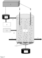
- a device H for cultivation of nitrifying biomass was constructed, the scheme of which is shown in Fig. 5 .
- the mobile unit of the nitrifying biomass cultivation device capable of processing for example fugate, can be operated, for example, as a system described below.
- Tank 1 of the device used in the mobile unit was made of plastic (polypropylene, PP) and has the shape of a cylinder with an inner diameter of 1000 mm. The outer diameter is 1012 mm; the total height of the cylinder is 1800 mm. The maximum working volume of the tank is 1 m 3 .
- the pH value and the dissolved oxygen concentration can be measured and regulated using a measuring and control system consisting of a probe 6 for measuring pH, a probe 7 for measuring O 2 concentration, and a measuring and control unit 8 (interface and the control unit itself (GRYF XBP; GRYF HB, spol. s r.o., Czech Republic)).
- a measuring and control system consisting of a probe 6 for measuring pH, a probe 7 for measuring O 2 concentration, and a measuring and control unit 8 (interface and the control unit itself (GRYF XBP; GRYF HB, spol. s r.o., Czech Republic)
- GRYF HB spol. s r.o., Czech Republic
- the dosing of the substrate (fugate) into the tank 1 is provided by a peristaltic pump (PCD 1082; Kou ⁇ il dávkovac ⁇ ⁇ erpadla, Czech Republic).
- the dosing of fugate is continuous.
- the system works on the principle of a chemostat, i.e. without recirculation of nitrifying biomass.
- the air ensuring aerobic conditions and homogenization of the mixture in the reactor is continuously blown into the system by means of a source 3 of compressed air, in this case by means of a diaphragm blower capable of delivering 500 L of air per minute (Secoh JDK-S-500; Secoh, Japan).
- the device H described above was used to inoculate the reactor for nitrification of all fugate production with a total volume of 120 m 3 in the building of an agricultural biogas plant with an installed electrical capacity of 0.5 MW and a daily fugate production of 20 m 3 at an average TAN concentration of 3.0 g/L.
- the target nitrogen loading rate of the nitrification reactor was set at 0.5 kg/(m 3 ⁇ d).
- fugate was dosed into tank 1 of the device, filled with activated sludge from the municipal wastewater treatment plant, with an intensity corresponding to 10% of the value of target nitrogen loading rate which means 0.05 kg/(m 3 d) under conditions with pH adjusted to 7. This meant an initial flow rate of about 17 L per day.
- the device operated for 10 days. Subsequently, the system loading rate increased to approx. 0.10 kg/(m 3 ⁇ d) over a period of 10 days and gradually to 0.20; 0.30; 0.40 and 0.50 kg/(m 3 ⁇ d) over additional ten-day periods. This meant a gradual increase in daily flow to 34, 68, 102, 136 and 170 L per day. Thus, after 50 days, the target reactor nitrogen loading rate of approx. 0.5 kg/(m 3 ⁇ d) was reached. Simultaneously with the increase in the loading rate of the tank 1 of the device, the operating pH value was gradually decreased.
- the pH value decreased from 7 to 6.7, after another ten days to 6.5; after another ten days to 6 and finally after another 10 days to the pH value of 5.
- the effluent from tank 1 of the device could be used to inoculate the full scale nitrification reactor for fugate treatment.
- the outlet 5 from the tank 1 was collected in an IBC container and used in the following examples
- the aim was to realize the nitrification of all fugate production in the BGP with an installed electrical capacity of 0.5 MW and a daily fugate production of 20 m 3 at an average TAN concentration in the fugate of 3.0 g/L.
- Laboratory tests were performed to determine the target nitrogen load and the target pH.
- a laboratory simulation of the process was performed in a small reactor with a volume of 5 L, during which the conditions varied (fugate flowrate and thus nitrogen loading rate, pH, O 2 concentration) and the efficiency of the nitrification process was checked (the proportion of nitrified nitrogen in the effluent fugate was determined).
- the optimal target nitrogen load of the nitrification reactor was 0.5 kg/(m 3 ⁇ d). A value of 4.5 was identified as the optimal operating pH.
- the incorporation of the operating device capable of processing all daily production of the fugate took place as follows: The concentration of TAN in the fugate was 3.0 g/L and the target nitrogen loading rate of the system is to reach 0.5 kg/(m 3 ⁇ d), so it will be necessary to achieve a hydraulic retention time in the reactor of 6 days. The reactor must therefore accommodate the six-day fugate production.
- a nitrification reactor was built with tank 1 dimensions of 10 m x 3 m x 4 m (length x width x depth).
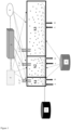
- the tank was made in the shape of a block, the material was concrete (the diagram of the reactor is in Figure 1 ).
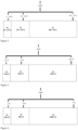
- the reactor tank was divided into three chambers with a volume of 10 m 3 ( S1 ), 30 m 3 ( S2 ) and 80 m 3 ( S3 ), see Figure 3 .
- An air distribution device G was connected to each of the tank chambers ( S1 , S2 , S3 ), connected to a source of compressed air (blower) and used to aerate all the tank chambers.
- the blower was connected to the measuring and control unit D , located outside the tank.
- Inlet A for the crude (raw) fugate was introduced into each of the tank chambers ( S1 , S2 , S3 ), as was outlet B for the nitrified fugate.
- a probe C for measuring pH, and a probe C' for measuring the O 2 concentration were placed, and both probes were connected to the measuring and control unit D . Then, an inlet for defoamer connected to a pump connected to the container F for defoamer was introduced into each of the chambers ( S1 , S2 , S3 ).
- a neutralization plant E comprising a pH adjusting agent tank (NaOH solution) and a pump was located outside the tank, and the neutralization plant E was connected to each chamber through a pH adjusting agent inlet.
- a pH adjusting agent tank NaOH solution
- a pump was located outside the tank, and the neutralization plant E was connected to each chamber through a pH adjusting agent inlet.
- the pump, neutralization station E and air distribution device G were connected to the measuring and control unit D by feedback.
- Example 3 Start-up of nitrification reactor I of Example 2
- the entire content of the IBC container i.e. 1 m 3
- the output 5 from nitrifying biomass cultivation device H was introduced into S1 (flow rate approx. 0.17 m 3 /d), as well as the raw fugate feed through inlet A , also in an amount corresponding to a flow rate of 0.17 m 3 /d.
- the chamber S1 therefore contained about 6.7 m 3 , section S2 20 m 3 and section S3 about 53.3 m 3 of processed fugate.
- the raw fugate was fed to the individual chambers via inlets A in an amount corresponding to their share in the total volume of the full scale reactor.
- about 8.3 per cent of the processed amount was fed to S1, about 25 per cent to S2 and about 66.7 per cent to S3 of the total amount of raw fugate fed to the system.
- This outlet 5 from the moment the chamber S3 was filled up and its volume divided into all three chambers, also opened into all three chambers and its dosed amount (volume) was distributed between the chambers in the same ratio as the volume ratio of these chambers. After all the chambers of the nitrification reactor tank had been filled up, this stream could already be stopped, because the amount of nitrifying organisms coming with it to the full scale reactor was already negligible in terms of the total volume of the full scale reactor.
- the aim was to realize the nitrification of all fugate production in the BGP with an installed electrical capacity of 1.5 MW and a daily fugate production of 60 m 3 at an average TAN concentration in the fugate of 5.0 g/L, with the need to nitrify 2/3 of the total daily production of fugate, i.e. 40 m 3 per day.
- a nitrification reactor of Figure 1 was built with tank 1 dimensions of 20 m x 5 m x 4 m (length x width x depth). The reactor was divided into three chambers with a volume of 20 m 3 (S1), 80 m 3 (S2) and 300 m 3 (S3), see Figure 1 and 4 .
- An air distribution device G was connected to each of the tank chambers, connected to a source of compressed air (blower) and used to aerate all the tank chambers.
- the blower was connected to the measuring and control unit D located outside the tank by feedback.
- Inlet A for the raw fugate was introduced into each of the tank chambers ( S1 , S2, S3 ), as was outlet B for the nitrified fugate.
- a probe C for measuring pH, and a probe C' for measuring the O 2 concentration were placed, and both probes were connected to the measuring and control unit D . Then, an inlet for defoamer connected to a pump connected to the container F for defoamer was introduced into each of the chambers ( S1 , S2 , S3 ).
- a neutralization plant E comprising a pH adjusting agent tank (Ca(OH) 2 solution) and a pump was located outside the tank, and the neutralization plant E was connected to each chamber ( S1 , S2, S3) through a pH adjusting agent inlet.
- a pH adjusting agent tank Ca(OH) 2 solution
- a pump was located outside the tank, and the neutralization plant E was connected to each chamber ( S1 , S2, S3) through a pH adjusting agent inlet.
- the pump, neutralization station E and air distribution device G were connected to the measuring and control unit D by feedback.
- Example 5 Start-up of nitrification reactor II of Example 4.
- the daily flow rate of raw fugate could be gradually increased to 0.55; 0.90 and 1.40 m 3 /d.
- chamber S1 was filled up.
- all the liquid contained in S1 was pumped into S2 and the gradual filling of the chamber S2 started.
- the daily flow rate of raw fugate could be gradually increased to 2.1; 3.2; 4.9 and 7.4 m 3 , and at the end of the period with a daily flow of 7.4 m 3 , S2 was completely filled up.
- all the liquid contained in S2 was pumped into S3 and the gradual filling of the chamber S3 started.
- outlet 5 from the nitrification biomass cultivation device H according to Example 1 was also added to the full scale reactor in order to enrich the system with nitrifying bacteria.
- This outlet 5 from the moment the chamber S3 was filled up and its volume divided into all three chambers, also opened into all three chambers ( S1 , S2 , S3 ) and its dosed amount (volume) was distributed between the chambers in the same ratio as the volume ratio of these chambers.
Landscapes
- Chemical & Material Sciences (AREA)
- Health & Medical Sciences (AREA)
- Organic Chemistry (AREA)
- Life Sciences & Earth Sciences (AREA)
- Engineering & Computer Science (AREA)
- Bioinformatics & Cheminformatics (AREA)
- Zoology (AREA)
- Wood Science & Technology (AREA)
- Sustainable Development (AREA)
- Microbiology (AREA)
- Biotechnology (AREA)
- Biomedical Technology (AREA)
- Biochemistry (AREA)
- General Engineering & Computer Science (AREA)
- General Health & Medical Sciences (AREA)
- Genetics & Genomics (AREA)
- Analytical Chemistry (AREA)
- Clinical Laboratory Science (AREA)
- Purification Treatments By Anaerobic Or Anaerobic And Aerobic Bacteria Or Animals (AREA)
Claims (8)
- Mehrkammer-Nitrifikationsreaktor zur Fugatverarbeitung, dadurch gekennzeichnet, dass er umfasst:- einen Tank, der drei separate Kammern (S1, S2, S3) umfasst, wobei die Kammern voneinander unterschiedliche Volumina aufweisen, wobei das Volumen der ersten Kammer (S1) kleiner ist als das Volumen der zweiten Kammer (S2), das kleiner ist als das Volumen der dritten Kammer (S3), und wobei der Tank ferner eine Luftverteilungsvorrichtung (G) umfasst, die mit einer Druckluftquelle verbunden ist;- eine außerhalb des Tanks angeordnete Mess- und Steuereinheit (D);- einen Einlass (A) für Rohfugat in jede der Tankkammern (S1, S2, S3);- einen Auslass (B) für das nitrifizierte Fugat aus jeder der Tankkammern (S1, S2, S3);- eine Sonde (C) zur Messung des pH-Werts, die sich in jeder Kammer (S1, S2, S3) befindet und mit der Mess- und Steuereinheit (D) verbunden ist;- eine Sonde (C') zur Messung der O2-Konzentration, die sich in jeder Kammer (S1, S2, S3) befindet und mit der Mess- und Steuereinheit (D) verbunden ist;- einen Einlass für einen Entschäumer in jeder der Kammern (S1, S2, S3), verbunden mit einer Pumpe, die mit einem Behälter (F) für Entschäumer verbunden ist;- eine Neutralisationsstation (E), die sich außerhalb des Tanks befindet und einen Tank für das pH-Einstellmittel und eine Pumpe umfasst, wobei die Neutralisationsstation (E) mit jeder Kammer (S1, S2, S3) über einen Einlass für das pH-Einstellmittel verbunden ist;wobei die Pumpe und die Luftverteilungsvorrichtung (G) durch Rückkopplung mit der Mess- und Steuereinheit (D) verbunden sind;und wobei das Volumen der ersten Kammer (S1) im Bereich von 5 bis 10 % des gesamten Reaktortankvolumens liegt, das Volumen der zweiten Kammer (S2) im Bereich von 20 bis 30 % des gesamten Reaktortankvolumens und das Volumen der dritten Kammer (S3) liegt im Bereich von 60 bis 75 % des gesamten Nitrifikationsreaktortankvolumens;und wobei die Vorrichtung weiterhin eine Pumpe umfasst, die dazu konfiguriert ist, den flüssigen Inhalt von der ersten Tankkammer (S1) in die zweite Tankkammer (S2) und von der zweiten Tankkammer (S2) in die dritte Tankkammer (S3) zu pumpen.
- Mehrkammer-Nitrifikationsreaktor nach Anspruch 1, dadurch gekennzeichnet, dass das Volumen der ersten Kammer (S1) 8,5 % des gesamten Reaktortankvolumens beträgt, das Volumen der zweiten Kammer (S2) 25,5 % des gesamten Reaktortankvolumens beträgt, und das Volumen der dritten Kammer (S3) beträgt 66 % des gesamten Nitrifikationsreaktortankvolumens.
- Mehrkammer-Nitrifikationsreaktor nach einem der vorhergehenden Ansprüche, dadurch gekennzeichnet, dass der Tank des Nitrifikationsreaktors aus Beton oder Kunststoff besteht und vorzugsweise ein Volumen im Bereich von 30 bis 500 m3 aufweist.
- Mehrkammer-Nitrifikationsreaktor nach einem der vorhergehenden Ansprüche, dadurch gekennzeichnet, dass jede Kammer (S1, S2, S3) ferner einen Einlass für nitrifizierende Biomasse aufweist, der zum Anschluss an einen Auslass (5) des Nitrifikationsbiomassekultivierungsgeräts (H) geeignet ist, das umfasst:- einen Tank (1), der mindestens ein Belüftungselement (2) umfasst, das an eine Druckluftquelle (3) angeschlossen ist;- außerhalb des Tanks (1) angeordnete Mess- und Steuereinheit (8);- einen Einlass (4) für Substrat, der sich im unteren Drittel der Höhe des Tanks (1) befindet;- einen Auslass (5) für nitrifizierende Biomasse, vorzugsweise im oberen Drittel der Höhe des Tanks (1) angeordnet;- eine pH-Messsonde (6), die sich im Tank (1) befindet und mit der Mess- und Steuereinheit (8) verbunden ist;- eine O2-Konzentrationsmesssonde (7), die sich im Tank (1) befindet und mit der Mess- und Steuereinheit (8) verbunden ist;- einen Einlass (9) für pH-Einstellmittel, verbunden mit einer Pumpe (10), die mit dem pH-Einstellmitteltank (11) verbunden ist;wobei die Pumpe (10) und das Belüftungselement (2) durch Rückkopplung mit der Mess- und Steuereinheit (8) verbunden sind.
- Verfahren zur Inbetriebnahme des Mehrkammer-Nitrifikationsreaktors nach einem der vorhergehenden Ansprüche 1 bis 4 für eine gegebene Biogasanlage, dadurch gekennzeichnet, dass es folgende Schritte umfasst:a) Bestimmung der angestrebten Stickstoffbeladungsrate (Bv) und des Betriebs-pH-Wertes des Mehrkammer-Nitrifikationsreaktors;b) Berechnen des Reaktorvolumens des Mehrkammer-Nitrifikationsreaktors gemäß Gleichung (1):

V ist das Volumen des Mehrkammer-Nitrifikationsreaktors (m3); Bv ist die angestrebte Stickstoffbeladungsrate (kg/(m3··d)); c ist die TAN-Konzentration im Rohfugat (kg/m3); Q ist die Zieldurchflussrate des im Reaktor zu verarbeitenden Fugats (m3/d);c) Aufbau des Mehrkammer-Nitrifikationsreaktors nach einem der vorhergehenden Ansprüche 1 bis 5, dessen Gesamttankvolumen in Schritt b) bestimmt wurde;d) in der ersten Kammer (S1) des Nitrifikationsreaktortanks wird eine nitrifizierende Kultur von Mikroorganismen, die das Fugat verarbeiten können, platziert und das von der jeweiligen Biogasanlage produzierte Rohfugat wird nach und nach in die erste Kammer (S1) eingespeist mit täglicher Zuflussrate von 0,25 bis 5 % der gesamten täglichen Fugatproduktion der jeweiligen Biogasanlage;e) anschließend wird die Zuflussrate des in die erste Kammer (S1) dosierten Rohfugats auf den durch Gleichung (2) bestimmten Wert Q erhöht: wobei V das aktuelle Volumen der Mischung in der gegebenen Kammer (m3) ist; Bv ist die angestrebte Stickstoffbeladungsrate (kg/(m3·d)); c ist die TAN-Konzentration im Fugat (kg/m3) und Q ist die Zuflussrate des in die Kammer dosierten Fugats (m3/d);wobei diese Zuflussrate fünf Tage lang aufrechterhalten wird;f) Wiederholen von Schritt e) in Fünf-Tages-Zyklen, bis die erste Kammer (S1) vollständig gefüllt ist;g) das gesamte in der ersten Kammer (S1) enthaltene Gemisch wird in die zweite Kammer (S2) gepumpt und die allmähliche Befüllung der zweiten Kammer (S2) beginnt mit der durch die Gleichung (2) bestimmten Zuflussrate des Rohfugats; wobei die Zuflussrate in Fünf-Tages-Zyklen gemäß Gleichung (2) erhöht wird, bis die zweite Kammer (S2) vollständig gefüllt ist;h) das gesamte in der zweiten Kammer (S2) enthaltene Gemisch wird in die dritte Kammer (S3) gepumpt und die allmähliche Befüllung der dritten Kammer (S3) beginnt mit der durch die Gleichung (2) bestimmten Zuflussrate des Rohfugats; wobei die Zuflussrate in Fünf-Tages-Zyklen gemäß Gleichung (2) erhöht wird, bis die dritte Kammer (S3) vollständig gefüllt ist;i) ein Teil der Mischung aus der dritten Kammer (S3) wird in die erste Kammer (S 1) und die zweite Kammer (S2) überführt, so dass sich der prozentuale Volumenanteil der Flüssigkeit in jeder der Kammern, bezogen auf das Maximalvolumen der jeweiligen Kammer, ist in allen Kammern (S1, S2, S3) gleich;j) Rohfugat wird gleichzeitig in alle Kammern (S1, S2, S3) dosiert, wobei die Zuflussdosierungsraten durch die Gleichung (2) für jede der Kammern (S1, S2, S3) bestimmt werden; und wobei die Zuflussrate des Rohfugats in fünftägigen Zyklen erhöht wird, bis der Wert erreicht ist, der der angestrebten täglichen Fugatproduktion der jeweiligen Biogasanlage entspricht, und somit der Nitrifikationsreaktor in den Vollbetrieb genommen wird.
 - Verfahren zur Inbetriebnahme des Mehrkammer-Nitrifikationsreaktors nach Anspruch 5, dadurch gekennzeichnet, dass die nitrifizierende Kultur von Mikroorganismen, die in der Lage sind, das Fugat in Schritt d) zu verarbeiten, aus einem Nitrifikationsbiomassekultivierungsgerät (H), definiert in Anspruch 4, gewonnen wird durch ein Verfahren, das die folgenden Schritte umfasst:- der Tank (1) des Nitrifikationsbiomassekultivierungsgeräts (H) wird mit Inokulum gefüllt;- die angestrebte Stickstoffbeladungsrate und der angestrebte Betriebs-pH-Wert werden bestimmt;- dann wird, innerhalb von 10 Tagen, das für den Anbau von Nitrifikationsbiomasse geeignete Substrat in den Tank des Nitrifikationsbiomassekultivierungsgeräts (H) dosiert über den Substrateinlass (4), vorzugsweise mit der Schlauchpumpe, mit einer Intensität entsprechend 10% des Zielwerts der Stickstoffbeladungsrate, mit auf 7 eingestelltem pH-Wert und mit Belüftung mithilfe des Belüftungselements (2);- dann wird die Systembeladungsrate für 10 Tage auf 20% des Zielwerts der Stickstoffbeladungsrate erhöht, wobei der pH-Wert auf 6,7 eingestellt wird und die Belüftung mit dem Belüftungselement (2) erfolgt.- dann wird die Systembeladungsrate für 10 Tage auf 40% des Zielwertes der Stickstoffbeladungsrate erhöht, wobei der pH-Wert auf 6,5 eingestellt wird und die Belüftung mit dem Belüftungselement (2) erfolgt.- dann wird die Systembeladungsrate für 10 Tage auf 60% des Zielwerts der Stickstoffbeladungsrate erhöht, wobei der pH-Wert auf 6 eingestellt wird und die Belüftung mit dem Belüftungselement (2) erfolgt.- dann wird die Systembeladungsrate für 10 Tage auf 80% des Zielwertes der Stickstoffbeladungsrate erhöht, wobei der pH-Wert auf den Ziel-pH-Wert für den Betrieb eingestellt wird und die Belüftung mithilfe des Belüftungselements erfolgt (2);wobei das für den Anbau von Nitrifikationsbiomasse geeignete Substrat aus der Gruppe ausgewählt ist, die Fugat, bei der Entwässerung von anaerob vergärtem Schlamm gebildetes Schmutzwasser, Deponiesickerwasser und Industrieabwasser mit einem TAN-Gehalt von mindestens 500 mg/L umfasst;und wobei das Inokulum vorzugsweise Belebtschlamm ist, der in der biologischen Stufe einer kommunalen Abwasseraufbereitungsanlage gesammelt wird.
- Verfahren zur Inbetriebnahme des Mehrkammer-Nitrifikationsreaktors nach den Ansprüchen 5 oder 6, dadurch gekennzeichnet, dass gleichzeitig mit der Dosierung von Rohfugat in einzelne Kammern des Nitrifikationsreaktors in den Schritten d) bis j), nitrifizierende Biomasse, erzeugt durch das in Anspruch 4 definiertes Nitrifikationsbiomassekultivierungsgerät (H), in die Kammern dosiert wird; vorzugsweise mit einer Dosierungsrate im Bereich von 0,10 m3/Tag bis 0,20 m3/Tag.
- Verwendung des Mehrkammer-Nitrifikationsreaktors nach einem der vorhergehenden Ansprüche 1 bis 4 zur Nitrifikation von Rohfugat aus Biogasanlagen.
Applications Claiming Priority (3)
| Application Number | Priority Date | Filing Date | Title |
|---|---|---|---|
| CZ202038384U CZ34803U1 (cs) | 2020-12-18 | 2020-12-18 | Vícekomorový nitrifikační reaktor pro zpracování fugátu |
| CZ2020-694A CZ309691B6 (cs) | 2020-12-18 | 2020-12-18 | Vícekomorový nitrifikační reaktor pro zpracování fugátu a způsob jeho zapracování do plného provozu |
| PCT/CZ2021/050153 WO2022127952A1 (en) | 2020-12-18 | 2021-12-17 | A multi-chamber nitrification reactor for fugate processing and method of its start-up into full scale operation |
Publications (3)
| Publication Number | Publication Date |
|---|---|
| EP4244331A1 EP4244331A1 (de) | 2023-09-20 |
| EP4244331B1 true EP4244331B1 (de) | 2024-07-17 |
| EP4244331C0 EP4244331C0 (de) | 2024-07-17 |
Family
ID=80351192
Family Applications (1)
| Application Number | Title | Priority Date | Filing Date |
|---|---|---|---|
| EP21856899.6A Active EP4244331B1 (de) | 2020-12-18 | 2021-12-17 | Mehrkammer-nitrifikationsreaktor zur fugate-verarbeitung und verfahren zu dessen inbetriebnahme in vollmassstabbetrieb |
Country Status (2)
| Country | Link |
|---|---|
| EP (1) | EP4244331B1 (de) |
| WO (1) | WO2022127952A1 (de) |
Family Cites Families (2)
| Publication number | Priority date | Publication date | Assignee | Title |
|---|---|---|---|---|
| DE102007005069A1 (de) * | 2007-01-26 | 2008-07-31 | Uts Biogastechnik Gmbh | Biogasanlage |
| CN106520610B (zh) * | 2016-11-10 | 2023-04-28 | 中冶华天工程技术有限公司 | 复合硝化细菌菌剂的生产工艺及硝化细菌发酵的分批培养发酵罐系统 |
-
2021
- 2021-12-17 WO PCT/CZ2021/050153 patent/WO2022127952A1/en not_active Ceased
- 2021-12-17 EP EP21856899.6A patent/EP4244331B1/de active Active
Also Published As
| Publication number | Publication date |
|---|---|
| EP4244331A1 (de) | 2023-09-20 |
| WO2022127952A1 (en) | 2022-06-23 |
| EP4244331C0 (de) | 2024-07-17 |
Similar Documents
| Publication | Publication Date | Title |
|---|---|---|
| CA2083199C (en) | Method for the treatment of sewage and installation to be used for this method | |
| CN1204061C (zh) | 处理废水的方法和设备 | |
| EP1957413B1 (de) | Membran zur abwasserbehandlung | |
| US20110127214A1 (en) | Energy optimization in an anaerobic, facultative, anoxic aerobic plant, using fine bubbles, without sludge production | |
| CN102674539A (zh) | 一种基于膜生物反应器的硝化污泥高效富集培养系统及方法 | |
| CA2374537A1 (en) | Method of high-concentration culture of nitrifying bacteria or denitrifying bacteria contained in activated sludge, culture promoter to be used in high-concentration culture method of nitrifying bacteria, and mehtod of weight loss treatment of activated sludge | |
| CN105683094A (zh) | 使用pH控制系统和具有高生化需氧量水平的工业污水的单细胞生物质生产的方法和装置 | |
| CN110642380A (zh) | 一种规模化室外池微生物处理稀土废水的方法 | |
| CN103011493A (zh) | 一种高磷、高氨氮污水除磷脱氮及资源回收方法 | |
| Münch et al. | Suspended carrier technology allows upgrading high-rate activated sludge plants for nitrogen removal via process intensification | |
| CN108298771A (zh) | 一种养猪场废弃物处理方法 | |
| CN109022271A (zh) | 一种多级放大的硝化菌全自动在线扩培装置及扩培方法 | |
| US20030209489A1 (en) | System and method for remediation of waste | |
| KR102084454B1 (ko) | 순산소를 이용한 고농도 유기성폐기물의 고속 액비제조장치 및 그 제어방법 | |
| CZ297094B6 (cs) | Zpusob a zarízení k biologické úprave tekutiny pri generování bioplynu | |
| JP6202069B2 (ja) | 有機性排水の生物処理方法 | |
| EP4244331B1 (de) | Mehrkammer-nitrifikationsreaktor zur fugate-verarbeitung und verfahren zu dessen inbetriebnahme in vollmassstabbetrieb | |
| CN105152330A (zh) | 一种用于垃圾渗滤液的处理方法 | |
| EP2294018A2 (de) | Verfahren und vorrichtung zur reinigung von verschmutztem wasser | |
| KR100983829B1 (ko) | 메탄발효조를 이용하는 유기물의 부식화에 의한 폐수의처리방법 | |
| CN212924565U (zh) | 一体式短程硝化和厌氧氨氧化的快速原位启动装置 | |
| CN216584399U (zh) | 一种生活污水处理装置 | |
| KR102488754B1 (ko) | 하수처리장의 소화조 유출수 처리 장치 및 이를 이용한 처리 방법 | |
| CN111620442B (zh) | 一体式短程硝化/厌氧氨氧化的快速原位启动方法与装置 | |
| CZ34803U1 (cs) | Vícekomorový nitrifikační reaktor pro zpracování fugátu |
Legal Events
| Date | Code | Title | Description |
|---|---|---|---|
| STAA | Information on the status of an ep patent application or granted ep patent |
Free format text: STATUS: UNKNOWN |
|
| STAA | Information on the status of an ep patent application or granted ep patent |
Free format text: STATUS: THE INTERNATIONAL PUBLICATION HAS BEEN MADE |
|
| PUAI | Public reference made under article 153(3) epc to a published international application that has entered the european phase |
Free format text: ORIGINAL CODE: 0009012 |
|
| STAA | Information on the status of an ep patent application or granted ep patent |
Free format text: STATUS: REQUEST FOR EXAMINATION WAS MADE |
|
| 17P | Request for examination filed |
Effective date: 20230614 |
|
| AK | Designated contracting states |
Kind code of ref document: A1 Designated state(s): AL AT BE BG CH CY CZ DE DK EE ES FI FR GB GR HR HU IE IS IT LI LT LU LV MC MK MT NL NO PL PT RO RS SE SI SK SM TR |
|
| GRAP | Despatch of communication of intention to grant a patent |
Free format text: ORIGINAL CODE: EPIDOSNIGR1 |
|
| STAA | Information on the status of an ep patent application or granted ep patent |
Free format text: STATUS: GRANT OF PATENT IS INTENDED |
|
| DAV | Request for validation of the european patent (deleted) | ||
| DAX | Request for extension of the european patent (deleted) | ||
| INTG | Intention to grant announced |
Effective date: 20240318 |
|
| GRAS | Grant fee paid |
Free format text: ORIGINAL CODE: EPIDOSNIGR3 |
|
| GRAA | (expected) grant |
Free format text: ORIGINAL CODE: 0009210 |
|
| STAA | Information on the status of an ep patent application or granted ep patent |
Free format text: STATUS: THE PATENT HAS BEEN GRANTED |
|
| AK | Designated contracting states |
Kind code of ref document: B1 Designated state(s): AL AT BE BG CH CY CZ DE DK EE ES FI FR GB GR HR HU IE IS IT LI LT LU LV MC MK MT NL NO PL PT RO RS SE SI SK SM TR |
|
| REG | Reference to a national code |
Ref country code: CH Ref legal event code: EP |
|
| REG | Reference to a national code |
Ref country code: DE Ref legal event code: R096 Ref document number: 602021015960 Country of ref document: DE |
|
| REG | Reference to a national code |
Ref country code: IE Ref legal event code: FG4D |
|
| U01 | Request for unitary effect filed |
Effective date: 20240717 |
|
| U07 | Unitary effect registered |
Designated state(s): AT BE BG DE DK EE FI FR IT LT LU LV MT NL PT SE SI Effective date: 20240730 |
|
| PG25 | Lapsed in a contracting state [announced via postgrant information from national office to epo] |
Ref country code: NO Free format text: LAPSE BECAUSE OF FAILURE TO SUBMIT A TRANSLATION OF THE DESCRIPTION OR TO PAY THE FEE WITHIN THE PRESCRIBED TIME-LIMIT Effective date: 20241017 |
|
| PG25 | Lapsed in a contracting state [announced via postgrant information from national office to epo] |
Ref country code: GR Free format text: LAPSE BECAUSE OF FAILURE TO SUBMIT A TRANSLATION OF THE DESCRIPTION OR TO PAY THE FEE WITHIN THE PRESCRIBED TIME-LIMIT Effective date: 20241018 Ref country code: PL Free format text: LAPSE BECAUSE OF FAILURE TO SUBMIT A TRANSLATION OF THE DESCRIPTION OR TO PAY THE FEE WITHIN THE PRESCRIBED TIME-LIMIT Effective date: 20240717 |
|
| U20 | Renewal fee for the european patent with unitary effect paid |
Year of fee payment: 4 Effective date: 20241218 |
|
| PG25 | Lapsed in a contracting state [announced via postgrant information from national office to epo] |
Ref country code: IS Free format text: LAPSE BECAUSE OF FAILURE TO SUBMIT A TRANSLATION OF THE DESCRIPTION OR TO PAY THE FEE WITHIN THE PRESCRIBED TIME-LIMIT Effective date: 20241117 |
|
| PG25 | Lapsed in a contracting state [announced via postgrant information from national office to epo] |
Ref country code: HR Free format text: LAPSE BECAUSE OF FAILURE TO SUBMIT A TRANSLATION OF THE DESCRIPTION OR TO PAY THE FEE WITHIN THE PRESCRIBED TIME-LIMIT Effective date: 20240717 |
|
| PG25 | Lapsed in a contracting state [announced via postgrant information from national office to epo] |
Ref country code: ES Free format text: LAPSE BECAUSE OF FAILURE TO SUBMIT A TRANSLATION OF THE DESCRIPTION OR TO PAY THE FEE WITHIN THE PRESCRIBED TIME-LIMIT Effective date: 20240717 Ref country code: RS Free format text: LAPSE BECAUSE OF FAILURE TO SUBMIT A TRANSLATION OF THE DESCRIPTION OR TO PAY THE FEE WITHIN THE PRESCRIBED TIME-LIMIT Effective date: 20241017 |
|
| PG25 | Lapsed in a contracting state [announced via postgrant information from national office to epo] |
Ref country code: RS Free format text: LAPSE BECAUSE OF FAILURE TO SUBMIT A TRANSLATION OF THE DESCRIPTION OR TO PAY THE FEE WITHIN THE PRESCRIBED TIME-LIMIT Effective date: 20241017 Ref country code: PL Free format text: LAPSE BECAUSE OF FAILURE TO SUBMIT A TRANSLATION OF THE DESCRIPTION OR TO PAY THE FEE WITHIN THE PRESCRIBED TIME-LIMIT Effective date: 20240717 Ref country code: NO Free format text: LAPSE BECAUSE OF FAILURE TO SUBMIT A TRANSLATION OF THE DESCRIPTION OR TO PAY THE FEE WITHIN THE PRESCRIBED TIME-LIMIT Effective date: 20241017 Ref country code: IS Free format text: LAPSE BECAUSE OF FAILURE TO SUBMIT A TRANSLATION OF THE DESCRIPTION OR TO PAY THE FEE WITHIN THE PRESCRIBED TIME-LIMIT Effective date: 20241117 Ref country code: HR Free format text: LAPSE BECAUSE OF FAILURE TO SUBMIT A TRANSLATION OF THE DESCRIPTION OR TO PAY THE FEE WITHIN THE PRESCRIBED TIME-LIMIT Effective date: 20240717 Ref country code: GR Free format text: LAPSE BECAUSE OF FAILURE TO SUBMIT A TRANSLATION OF THE DESCRIPTION OR TO PAY THE FEE WITHIN THE PRESCRIBED TIME-LIMIT Effective date: 20241018 Ref country code: ES Free format text: LAPSE BECAUSE OF FAILURE TO SUBMIT A TRANSLATION OF THE DESCRIPTION OR TO PAY THE FEE WITHIN THE PRESCRIBED TIME-LIMIT Effective date: 20240717 |
|
| PG25 | Lapsed in a contracting state [announced via postgrant information from national office to epo] |
Ref country code: SM Free format text: LAPSE BECAUSE OF FAILURE TO SUBMIT A TRANSLATION OF THE DESCRIPTION OR TO PAY THE FEE WITHIN THE PRESCRIBED TIME-LIMIT Effective date: 20240717 |
|
| PG25 | Lapsed in a contracting state [announced via postgrant information from national office to epo] |
Ref country code: CZ Free format text: LAPSE BECAUSE OF FAILURE TO SUBMIT A TRANSLATION OF THE DESCRIPTION OR TO PAY THE FEE WITHIN THE PRESCRIBED TIME-LIMIT Effective date: 20240717 |
|
| PG25 | Lapsed in a contracting state [announced via postgrant information from national office to epo] |
Ref country code: SK Free format text: LAPSE BECAUSE OF FAILURE TO SUBMIT A TRANSLATION OF THE DESCRIPTION OR TO PAY THE FEE WITHIN THE PRESCRIBED TIME-LIMIT Effective date: 20240717 |
|
| PLBE | No opposition filed within time limit |
Free format text: ORIGINAL CODE: 0009261 |
|
| STAA | Information on the status of an ep patent application or granted ep patent |
Free format text: STATUS: NO OPPOSITION FILED WITHIN TIME LIMIT |
|
| 26N | No opposition filed |
Effective date: 20250422 |
|
| PG25 | Lapsed in a contracting state [announced via postgrant information from national office to epo] |
Ref country code: MC Free format text: LAPSE BECAUSE OF FAILURE TO SUBMIT A TRANSLATION OF THE DESCRIPTION OR TO PAY THE FEE WITHIN THE PRESCRIBED TIME-LIMIT Effective date: 20240717 |
|
| REG | Reference to a national code |
Ref country code: CH Ref legal event code: PL |
|
| PG25 | Lapsed in a contracting state [announced via postgrant information from national office to epo] |
Ref country code: CH Free format text: LAPSE BECAUSE OF NON-PAYMENT OF DUE FEES Effective date: 20241231 |
|
| PG25 | Lapsed in a contracting state [announced via postgrant information from national office to epo] |
Ref country code: IE Free format text: LAPSE BECAUSE OF NON-PAYMENT OF DUE FEES Effective date: 20241217 |
|
| PG25 | Lapsed in a contracting state [announced via postgrant information from national office to epo] |
Ref country code: RO Free format text: LAPSE BECAUSE OF FAILURE TO SUBMIT A TRANSLATION OF THE DESCRIPTION OR TO PAY THE FEE WITHIN THE PRESCRIBED TIME-LIMIT Effective date: 20240717 |
|
| U20 | Renewal fee for the european patent with unitary effect paid |
Year of fee payment: 5 Effective date: 20251230 |