EP4245385B1 - Dispositif de marche virtuelle et procédé de marche virtuelle - Google Patents
Dispositif de marche virtuelle et procédé de marche virtuelle Download PDFInfo
- Publication number
- EP4245385B1 EP4245385B1 EP22165454.4A EP22165454A EP4245385B1 EP 4245385 B1 EP4245385 B1 EP 4245385B1 EP 22165454 A EP22165454 A EP 22165454A EP 4245385 B1 EP4245385 B1 EP 4245385B1
- Authority
- EP
- European Patent Office
- Prior art keywords
- feet
- virtual
- walking
- human body
- foot
- Prior art date
- Legal status (The legal status is an assumption and is not a legal conclusion. Google has not performed a legal analysis and makes no representation as to the accuracy of the status listed.)
- Active
Links
Images


Classifications
-
- A—HUMAN NECESSITIES
- A63—SPORTS; GAMES; AMUSEMENTS
- A63B—APPARATUS FOR PHYSICAL TRAINING, GYMNASTICS, SWIMMING, CLIMBING, OR FENCING; BALL GAMES; TRAINING EQUIPMENT
- A63B22/00—Exercising apparatus specially adapted for conditioning the cardio-vascular system, for training agility or co-ordination of movements
- A63B22/02—Exercising apparatus specially adapted for conditioning the cardio-vascular system, for training agility or co-ordination of movements with movable endless bands, e.g. treadmills
-
- G—PHYSICS
- G05—CONTROLLING; REGULATING
- G05D—SYSTEMS FOR CONTROLLING OR REGULATING NON-ELECTRIC VARIABLES
- G05D1/00—Control of position, course, altitude or attitude of land, water, air or space vehicles, e.g. using automatic pilots
- G05D1/02—Control of position or course in two dimensions
- G05D1/021—Control of position or course in two dimensions specially adapted to land vehicles
- G05D1/0212—Control of position or course in two dimensions specially adapted to land vehicles with means for defining a desired trajectory
- G05D1/0223—Control of position or course in two dimensions specially adapted to land vehicles with means for defining a desired trajectory involving speed control of the vehicle
-
- A—HUMAN NECESSITIES
- A63—SPORTS; GAMES; AMUSEMENTS
- A63B—APPARATUS FOR PHYSICAL TRAINING, GYMNASTICS, SWIMMING, CLIMBING, OR FENCING; BALL GAMES; TRAINING EQUIPMENT
- A63B22/00—Exercising apparatus specially adapted for conditioning the cardio-vascular system, for training agility or co-ordination of movements
- A63B22/02—Exercising apparatus specially adapted for conditioning the cardio-vascular system, for training agility or co-ordination of movements with movable endless bands, e.g. treadmills
- A63B22/0285—Physical characteristics of the belt, e.g. material, surface, indicia
-
- A—HUMAN NECESSITIES
- A63—SPORTS; GAMES; AMUSEMENTS
- A63B—APPARATUS FOR PHYSICAL TRAINING, GYMNASTICS, SWIMMING, CLIMBING, OR FENCING; BALL GAMES; TRAINING EQUIPMENT
- A63B22/00—Exercising apparatus specially adapted for conditioning the cardio-vascular system, for training agility or co-ordination of movements
- A63B22/20—Exercising apparatus specially adapted for conditioning the cardio-vascular system, for training agility or co-ordination of movements using rollers, wheels, castors or the like, e.g. gliding means, to be moved over the floor or other surface, e.g. guide tracks, during exercising
-
- A—HUMAN NECESSITIES
- A63—SPORTS; GAMES; AMUSEMENTS
- A63B—APPARATUS FOR PHYSICAL TRAINING, GYMNASTICS, SWIMMING, CLIMBING, OR FENCING; BALL GAMES; TRAINING EQUIPMENT
- A63B24/00—Electric or electronic controls for exercising apparatus of preceding groups; Controlling or monitoring of exercises, sportive games, training or athletic performances
- A63B24/0062—Monitoring athletic performances, e.g. for determining the work of a user on an exercise apparatus, the completed jogging or cycling distance
-
- A—HUMAN NECESSITIES
- A63—SPORTS; GAMES; AMUSEMENTS
- A63B—APPARATUS FOR PHYSICAL TRAINING, GYMNASTICS, SWIMMING, CLIMBING, OR FENCING; BALL GAMES; TRAINING EQUIPMENT
- A63B24/00—Electric or electronic controls for exercising apparatus of preceding groups; Controlling or monitoring of exercises, sportive games, training or athletic performances
- A63B24/0087—Electric or electronic controls for exercising apparatus of groups A63B21/00 - A63B23/00, e.g. controlling load
-
- A—HUMAN NECESSITIES
- A63—SPORTS; GAMES; AMUSEMENTS
- A63B—APPARATUS FOR PHYSICAL TRAINING, GYMNASTICS, SWIMMING, CLIMBING, OR FENCING; BALL GAMES; TRAINING EQUIPMENT
- A63B71/00—Games or sports accessories not covered in groups A63B1/00 - A63B69/00
- A63B71/06—Indicating or scoring devices for games or players, or for other sports activities
- A63B71/0619—Displays, user interfaces and indicating devices, specially adapted for sport equipment, e.g. display mounted on treadmills
- A63B71/0622—Visual, audio or audio-visual systems for entertaining, instructing or motivating the user
-
- G—PHYSICS
- G05—CONTROLLING; REGULATING
- G05D—SYSTEMS FOR CONTROLLING OR REGULATING NON-ELECTRIC VARIABLES
- G05D1/00—Control of position, course, altitude or attitude of land, water, air or space vehicles, e.g. using automatic pilots
- G05D1/02—Control of position or course in two dimensions
- G05D1/021—Control of position or course in two dimensions specially adapted to land vehicles
- G05D1/0212—Control of position or course in two dimensions specially adapted to land vehicles with means for defining a desired trajectory
- G05D1/0221—Control of position or course in two dimensions specially adapted to land vehicles with means for defining a desired trajectory involving a learning process
-
- G—PHYSICS
- G05—CONTROLLING; REGULATING
- G05D—SYSTEMS FOR CONTROLLING OR REGULATING NON-ELECTRIC VARIABLES
- G05D1/00—Control of position, course, altitude or attitude of land, water, air or space vehicles, e.g. using automatic pilots
- G05D1/02—Control of position or course in two dimensions
- G05D1/021—Control of position or course in two dimensions specially adapted to land vehicles
- G05D1/0276—Control of position or course in two dimensions specially adapted to land vehicles using signals provided by a source external to the vehicle
-
- G—PHYSICS
- G06—COMPUTING OR CALCULATING; COUNTING
- G06F—ELECTRIC DIGITAL DATA PROCESSING
- G06F3/00—Input arrangements for transferring data to be processed into a form capable of being handled by the computer; Output arrangements for transferring data from processing unit to output unit, e.g. interface arrangements
- G06F3/01—Input arrangements or combined input and output arrangements for interaction between user and computer
- G06F3/011—Arrangements for interaction with the human body, e.g. for user immersion in virtual reality
-
- A—HUMAN NECESSITIES
- A63—SPORTS; GAMES; AMUSEMENTS
- A63B—APPARATUS FOR PHYSICAL TRAINING, GYMNASTICS, SWIMMING, CLIMBING, OR FENCING; BALL GAMES; TRAINING EQUIPMENT
- A63B22/00—Exercising apparatus specially adapted for conditioning the cardio-vascular system, for training agility or co-ordination of movements
- A63B22/0015—Exercising apparatus specially adapted for conditioning the cardio-vascular system, for training agility or co-ordination of movements with an adjustable movement path of the support elements
- A63B22/0017—Exercising apparatus specially adapted for conditioning the cardio-vascular system, for training agility or co-ordination of movements with an adjustable movement path of the support elements the adjustment being controlled by movement of the user
- A63B2022/002—Exercising apparatus specially adapted for conditioning the cardio-vascular system, for training agility or co-ordination of movements with an adjustable movement path of the support elements the adjustment being controlled by movement of the user electronically, e.g. by using a program
-
- A—HUMAN NECESSITIES
- A63—SPORTS; GAMES; AMUSEMENTS
- A63B—APPARATUS FOR PHYSICAL TRAINING, GYMNASTICS, SWIMMING, CLIMBING, OR FENCING; BALL GAMES; TRAINING EQUIPMENT
- A63B22/00—Exercising apparatus specially adapted for conditioning the cardio-vascular system, for training agility or co-ordination of movements
- A63B22/0025—Particular aspects relating to the orientation of movement paths of the limbs relative to the body; Relative relationship between the movements of the limbs
- A63B2022/0028—Particular aspects relating to the orientation of movement paths of the limbs relative to the body; Relative relationship between the movements of the limbs the movement path being non-parallel to the body-symmetrical-plane, e.g. support elements moving at an angle to the body-symmetrical-plane
-
- A—HUMAN NECESSITIES
- A63—SPORTS; GAMES; AMUSEMENTS
- A63B—APPARATUS FOR PHYSICAL TRAINING, GYMNASTICS, SWIMMING, CLIMBING, OR FENCING; BALL GAMES; TRAINING EQUIPMENT
- A63B22/00—Exercising apparatus specially adapted for conditioning the cardio-vascular system, for training agility or co-ordination of movements
- A63B22/02—Exercising apparatus specially adapted for conditioning the cardio-vascular system, for training agility or co-ordination of movements with movable endless bands, e.g. treadmills
- A63B2022/0271—Exercising apparatus specially adapted for conditioning the cardio-vascular system, for training agility or co-ordination of movements with movable endless bands, e.g. treadmills omnidirectional
-
- A—HUMAN NECESSITIES
- A63—SPORTS; GAMES; AMUSEMENTS
- A63B—APPARATUS FOR PHYSICAL TRAINING, GYMNASTICS, SWIMMING, CLIMBING, OR FENCING; BALL GAMES; TRAINING EQUIPMENT
- A63B24/00—Electric or electronic controls for exercising apparatus of preceding groups; Controlling or monitoring of exercises, sportive games, training or athletic performances
- A63B24/0087—Electric or electronic controls for exercising apparatus of groups A63B21/00 - A63B23/00, e.g. controlling load
- A63B2024/0093—Electric or electronic controls for exercising apparatus of groups A63B21/00 - A63B23/00, e.g. controlling load the load of the exercise apparatus being controlled by performance parameters, e.g. distance or speed
-
- A—HUMAN NECESSITIES
- A63—SPORTS; GAMES; AMUSEMENTS
- A63B—APPARATUS FOR PHYSICAL TRAINING, GYMNASTICS, SWIMMING, CLIMBING, OR FENCING; BALL GAMES; TRAINING EQUIPMENT
- A63B24/00—Electric or electronic controls for exercising apparatus of preceding groups; Controlling or monitoring of exercises, sportive games, training or athletic performances
- A63B24/0087—Electric or electronic controls for exercising apparatus of groups A63B21/00 - A63B23/00, e.g. controlling load
- A63B2024/0096—Electric or electronic controls for exercising apparatus of groups A63B21/00 - A63B23/00, e.g. controlling load using performance related parameters for controlling electronic or video games or avatars
-
- A—HUMAN NECESSITIES
- A63—SPORTS; GAMES; AMUSEMENTS
- A63B—APPARATUS FOR PHYSICAL TRAINING, GYMNASTICS, SWIMMING, CLIMBING, OR FENCING; BALL GAMES; TRAINING EQUIPMENT
- A63B71/00—Games or sports accessories not covered in groups A63B1/00 - A63B69/00
- A63B71/06—Indicating or scoring devices for games or players, or for other sports activities
- A63B71/0619—Displays, user interfaces and indicating devices, specially adapted for sport equipment, e.g. display mounted on treadmills
- A63B71/0622—Visual, audio or audio-visual systems for entertaining, instructing or motivating the user
- A63B2071/0638—Displaying moving images of recorded environment, e.g. virtual environment
-
- A—HUMAN NECESSITIES
- A63—SPORTS; GAMES; AMUSEMENTS
- A63B—APPARATUS FOR PHYSICAL TRAINING, GYMNASTICS, SWIMMING, CLIMBING, OR FENCING; BALL GAMES; TRAINING EQUIPMENT
- A63B2220/00—Measuring of physical parameters relating to sporting activity
- A63B2220/10—Positions
- A63B2220/13—Relative positions
-
- A—HUMAN NECESSITIES
- A63—SPORTS; GAMES; AMUSEMENTS
- A63B—APPARATUS FOR PHYSICAL TRAINING, GYMNASTICS, SWIMMING, CLIMBING, OR FENCING; BALL GAMES; TRAINING EQUIPMENT
- A63B2220/00—Measuring of physical parameters relating to sporting activity
- A63B2220/10—Positions
- A63B2220/16—Angular positions
-
- A—HUMAN NECESSITIES
- A63—SPORTS; GAMES; AMUSEMENTS
- A63B—APPARATUS FOR PHYSICAL TRAINING, GYMNASTICS, SWIMMING, CLIMBING, OR FENCING; BALL GAMES; TRAINING EQUIPMENT
- A63B2220/00—Measuring of physical parameters relating to sporting activity
- A63B2220/20—Distances or displacements
-
- A—HUMAN NECESSITIES
- A63—SPORTS; GAMES; AMUSEMENTS
- A63B—APPARATUS FOR PHYSICAL TRAINING, GYMNASTICS, SWIMMING, CLIMBING, OR FENCING; BALL GAMES; TRAINING EQUIPMENT
- A63B2220/00—Measuring of physical parameters relating to sporting activity
- A63B2220/30—Speed
- A63B2220/34—Angular speed
-
- A—HUMAN NECESSITIES
- A63—SPORTS; GAMES; AMUSEMENTS
- A63B—APPARATUS FOR PHYSICAL TRAINING, GYMNASTICS, SWIMMING, CLIMBING, OR FENCING; BALL GAMES; TRAINING EQUIPMENT
- A63B2220/00—Measuring of physical parameters relating to sporting activity
- A63B2220/40—Acceleration
- A63B2220/44—Angular acceleration
-
- A—HUMAN NECESSITIES
- A63—SPORTS; GAMES; AMUSEMENTS
- A63B—APPARATUS FOR PHYSICAL TRAINING, GYMNASTICS, SWIMMING, CLIMBING, OR FENCING; BALL GAMES; TRAINING EQUIPMENT
- A63B2220/00—Measuring of physical parameters relating to sporting activity
- A63B2220/50—Force related parameters
- A63B2220/51—Force
- A63B2220/52—Weight, e.g. weight distribution
-
- A—HUMAN NECESSITIES
- A63—SPORTS; GAMES; AMUSEMENTS
- A63B—APPARATUS FOR PHYSICAL TRAINING, GYMNASTICS, SWIMMING, CLIMBING, OR FENCING; BALL GAMES; TRAINING EQUIPMENT
- A63B2220/00—Measuring of physical parameters relating to sporting activity
- A63B2220/50—Force related parameters
- A63B2220/58—Measurement of force related parameters by electric or magnetic means
-
- A—HUMAN NECESSITIES
- A63—SPORTS; GAMES; AMUSEMENTS
- A63B—APPARATUS FOR PHYSICAL TRAINING, GYMNASTICS, SWIMMING, CLIMBING, OR FENCING; BALL GAMES; TRAINING EQUIPMENT
- A63B2220/00—Measuring of physical parameters relating to sporting activity
- A63B2220/80—Special sensors, transducers or devices therefor
- A63B2220/801—Contact switches
-
- A—HUMAN NECESSITIES
- A63—SPORTS; GAMES; AMUSEMENTS
- A63B—APPARATUS FOR PHYSICAL TRAINING, GYMNASTICS, SWIMMING, CLIMBING, OR FENCING; BALL GAMES; TRAINING EQUIPMENT
- A63B2220/00—Measuring of physical parameters relating to sporting activity
- A63B2220/80—Special sensors, transducers or devices therefor
- A63B2220/805—Optical or opto-electronic sensors
-
- A—HUMAN NECESSITIES
- A63—SPORTS; GAMES; AMUSEMENTS
- A63B—APPARATUS FOR PHYSICAL TRAINING, GYMNASTICS, SWIMMING, CLIMBING, OR FENCING; BALL GAMES; TRAINING EQUIPMENT
- A63B2220/00—Measuring of physical parameters relating to sporting activity
- A63B2220/80—Special sensors, transducers or devices therefor
- A63B2220/83—Special sensors, transducers or devices therefor characterised by the position of the sensor
- A63B2220/836—Sensors arranged on the body of the user
-
- G—PHYSICS
- G06—COMPUTING OR CALCULATING; COUNTING
- G06F—ELECTRIC DIGITAL DATA PROCESSING
- G06F3/00—Input arrangements for transferring data to be processed into a form capable of being handled by the computer; Output arrangements for transferring data from processing unit to output unit, e.g. interface arrangements
- G06F3/01—Input arrangements or combined input and output arrangements for interaction between user and computer
Definitions
- the present disclosure relates to a technical field of visual reality technology, and in particular to a device for visual walking and a method for visual walking.
- Movement control methods of a visual character are listed as follows.
- a first one is to control the virtual character by directional control buttons.
- a user controls a movement direction and speed of the virtual character by controlling buttons, joysticks, etc. on a device such as a control handle and a keyboard.
- This method is cheap and reliable.
- the vestibular organs of the human body that sense a movement state of the human body do not perceive the corresponding movement, and the difference between perception and physical perception brings the user a strong sense of dizziness.
- a second method is to control the virtual character by an omnidirectional movement platform.
- the user stands on the omnidirectional movement platform, walks, and runs in any direction in place.
- This method greatly reduces the difference between visual perception and physical perception in the virtual reality environment, and eliminates the user's dizziness.
- a full set of the omnidirectional movement platform is bulky and expensive, and is not suitable for home consumption entertainment.
- a third method is to control the virtual character by capturing human positions in a fixed environment (as disclosed in the CN patent application No. 201110430789.0 , titled "Skeleton Control of Three-dimensional Virtual World” and published as CN 102542160 A ).
- the user is in the fixed environment and position tracking devices are mounted around the fixed environment to capture a position of the user.
- the movement of the user in a certain space is mapped to the virtual world, thereby realizing a certain range of movement control.
- This method has relatively high requirements on the environment and is unable to realize movement in a large range in the virtual world.
- CN109388142A discloses a method and system for controlling virtual walking based on an inertial sensor. This method mainly controls the virtual character by obtaining torso data of the human body. However, real leg posture and movement is not effectively applied to the virtual world and the user experience is greatly reduced.
- Document CN 213 045 545 U relates to a shoe which is explicitly intended for being used with the omnidirectional exercise machine of patent CN 210 543 243 U .
- a purpose of the present disclosure is to provide a device for virtual walking and a method for virtual walking.
- the present disclosure has good adaptability, is stable and comfortable when walking.
- an inertial sensor and laser sensors on feet are applied to realize the real walking experience in virtual world and the device for visual walking of the present disclose has good fit and immersion.
- the present disclosure provides a device for virtual walking.
- the device for virtual walking comprises an omnidirectional exercise machine and foot wearable devices.
- the omnidirectional exercise machine comprises a base.
- a support piece is arranged on the base through a bearing.
- a running plate is arranged on the support piece.
- One side of the bearing is connected with two back support rods through rotating beams.
- a loading connector is arranged on upper ends of the two back support rods.
- the loading connector is sequentially connected with a waist omnidirectional motion controller and a binding belt.
- the base, the support piece, and the running plate are coaxially arranged.
- An inertial sensor is arranged inside the waist omnidirectional motion controller.
- the loading connector comprises a loading frame; rows of connecting holes are on one side of the loading frame.
- a mounting frame is arranged between the two back support rods.
- the mounting frame is fixedly connected with at least one row of connecting holes of the rows of connecting holes through connecting pieces.
- the foot wearable devices are configured to move on the running plate.
- Each of the foot wearable devices comprises a wrapping body.
- a pair of rollers are arranged on a rear end of a bottom portion of each wrapping body.
- a laser sensor is arranged on a front end of the bottom portion of each wrapping body.
- each roller In the device for virtual walking, a middle portion of each roller is wrapped with rubber.
- a mounting groove is provided on the bottom portion of each wrapping body.
- Two mounting bars are separately arranged on two sides of each mounting groove.
- An outer side of each of the mounting bar is connected with a corresponding roller.
- a flipping locking cover is arranged between each two mounting bars.
- Each flipping locking cover is configured to lock a corresponding pair of rollers.
- the present disclosure further provides a method for virtual walking of the device for visual walking.
- the method for visual walking comprise steps:
- the step of obtaining the human body posture data comprises:
- the virtual position of the feet and the movement speed of the feet are obtained by using the laser sensors to obtain movement position coordinates of the feet and a ground-off state of the feet.
- the movement speed of the feet and a direction of the feet are calculated based on the movement position coordinates of the feet, the ground-off state of the feet, and a bone reconstruction algorithm.
- the leg posture is obtained by taking the virtual position of the feet as a last bone point, calculating a length from the last bone point to an upper bone point and a direction from the last bone point to the upper bone point by the IK algorithm, determining a position of an upper joint bone, and calculating a length between each bone point and a rotating angle between each bone point in turn to obtain the leg posture.
- the steps of controlling the walking action of the virtual character comprises controlling a walking direction of the virtual character according to the human body posture data, controlling a walking speed of the virtual character according to the movement speed of the feet, and controlling a leg movement of the virtual character according to the leg posture.
- the present disclosure optimizes a structure of the loading connector of the omnidirectional excise machine.
- the present disclosure optimizes a structure of the loading connector of the omnidirectional excise machine.
- the foot wearable devices of the present disclosure adopts a mixed friction method combining rolling and sliding on the running plate.
- the rollers make the user walk stably and flexibly.
- the sliding friction of the rollers on the running plate is used as an auxiliary to achieve effect that the foot wearable devices full contact the running plate, which provides a comfortable walking experience.
- each flipping locking cover is integrated in each mounting groove.
- the flipping locking covers are configured to lock the rollers. When in use, the flipping locking covers are opened. After use, the flipping locking covers are closed to lock the rollers, so as to achieve a purpose of locking the rollers, achieve safety of the device for visual walking, and improves the aesthetics.
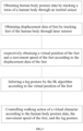
- the human body posture data is obtained by tracking the torso of the human body
- the displacement data of the left foot and the right foot is obtained by tracking the feet of the human body through the laser sensors
- the virtual position of the feet and the movement speed of the feet are respectively obtained according to the displacement data of the left foot and the right foot
- the leg posture is inferred by the IK algorithm according to the virtual position of the feet
- the walking action of the virtual character is controlled according to the human body posture data, the movement speed of the feet, and the leg posture.
- the user is able to obtain the displacement data of the left foot and the right foot in real time through the laser sensors, and then combine it with virtual reality.
- the present disclosure brings a better feeling to the user, has a better sense of fit and immersion.
- the present disclosure provides a device for virtual walking.
- the device for virtual walking comprises an omnidirectional exercise machine and foot wearable devices.
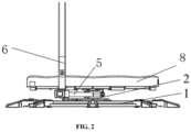
- the omnidirectional exercise machine comprises a base 1.
- a support piece 8 is arranged on the base 1 through a bearing 2.
- a running plate 3 is arranged on the support piece 8.
- One side of the bearing 2 is connected with two back support rods 6 through rotating beams 5.
- a loading connector 4 is arranged on upper ends of the two back support rods 6.
- the loading connector 4 is connected with a waist omnidirectional motion controller 7.
- the base 1, the support piece 8, and the running plate 5 are coaxially arranged.
- the omnidirectional exercise machine maintains the base 1, the bearing 2, the support piece 8, the running plate 3 and the loading connector 4 used in the prior art.
- the base 1 is placed or fixed on the ground as a whole to support a weight of the omnidirectional exercise machine and prevent the omnidirectional exercise machine from overturning.
- force acts on the support piece 8, so the bearing 2 and an overall bearing accessory assembly are driven to rotate.
- the support piece 8 is configured to fix the running plate 3 and is coaxially connected with the base 1, so that the force of the user acting on the running plate 3 is transmitted to the base 1 through the support piece 8, and is finally transmitted to the ground.
- the running plate 3 is a support carrier of the user and provides a range of activities for the user.
- the user stands on the running plate 3 to perform actions and operations.
- the loading connector 4 supports the back of the user so as to realize the action of the user.
- the waist omnidirectional motion controller 7 carefully support the waist of the user so as to realize the action of the user.
- the loading connector 4 comprises a loading frame 9, and sliding rails are arranged on two sides of an inner wall of the loading frame 9.
- a sliding block is arranged between the sliding rails.
- One side of the sliding block towards the running plate is connected to the waist omnidirectional motion controller 7 and the binding belt 12.
- An inertial sensor is arranged inside the waist omnidirectional motion controller 7.
- an infrared matrix sensor and several Hall sensors arranged in the waist omnidirectional motion controller 7 in the prior art are replaced with the inertial sensor.
- the inertial sensor is a 9-axis sensor.
- the 9-axis sensor comprises an accelerometer with 14-bit resolution and a range of ⁇ 16g, a uT magnetometer with 15-bit resolution and a detecting range of ⁇ 1300uT/ ⁇ 2500 (Z-axis), and a gyroscope with 16-bit resolution and a detecting range of ⁇ 2000 degree/s.
- the 9-axis sensor provides excellent 9-axis motion tracking.
- the waist omnidirectional motion controller 7 integrates an ARM ® Cortex TM -M0+ microcontroller that comprises Motion Engine firmware, which provides sophisticated signal processing algorithms to process sensor data and provide accurate real-time 3D orientation, heading, calibrated acceleration, and calibrated angular velocity.
- Rows of connecting holes 13 are on one side of the loading frame 9.
- a mounting frame 14 is arranged between the two back support rods 6.
- the mounting frame 14 is fixedly connected with at least one row of connecting holes 13 of the rows of connecting holes through connecting pieces.
- the rows of connecting hole 13 are arranged at a height of 140-200cm in equal difference, so as to meet a height requirements of different users,
- the foot wearable devices are configured to move on the running plate 3.
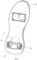
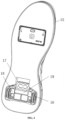
- Each of the foot wearable devices comprises a wrapping body 15.
- a pair of rollers 16 are arranged on a rear end of a bottom portion of each wrapping body 15.
- a laser sensor is arranged on a front end of the bottom portion of each wrapping body.
- a middle portion of each roller 16 is wrapped with rubber.
- a mounting groove 17 is provided on the bottom portion of each wrapping body 15.
- Two mounting bars 18 are separately arranged on two sides of each mounting groove 17.
- An outer side of each of the mounting bar 18 is connected with a corresponding roller 16.
- a flipping locking cover 19 is arranged between each two mounting bars 18.
- Each flipping locking cover 19 is configured to lock a corresponding pair of rollers 16.
- the foot wearable devices of the present disclosure adopts a mixed friction method combining rolling and sliding on the running plate.
- the rollers 16 make the user walk stably and flexibly.
- the sliding friction of the rollers 16 on the running plate is used as an auxiliary to achieve effect that the foot wearable devices full contact the running plate, which provides a comfortable walking experience.
- the middle portion of each roller is wrapped with high-strength rubber to achieve effect of buffering and noise reduction.
- each flipping locking cover 19 is integrated in each mounting groove 17. The flipping locking covers 19 are configured to lock the rollers 16. When in use, as shown in FIG.
- the flipping locking covers 19 are opened. After use, as shown in FIG. 3 , the flipping locking covers 19 are closed to lock the rollers 16, so as to achieve a purpose of locking the rollers, achieve safety of the device for visual walking, and improves the aesthetics.
- the present disclosure further provides a method for virtual walking based on the device for visual walking in Embodiment 1.
- human body posture data is obtained by tracking a torso of a human body through the inertial sensor (waist sensor).
- a direction perpendicular to the ground is obtained by the gyroscope in the inertial sensor (the gyroscope measures an earth's magnetic field with the help of a magnetometer to obtain the direction perpendicular to the ground; then, the gyroscope measures the angular acceleration value, and an angular velocity value is obtained by integrating the angular acceleration value in time).
- the angular velocity value is obtained by integrating the angular acceleration value in time. Then an error function of the attitude angle is iteratively calculated by a gradient descent method; and an error of the attitude angle is continuously corrected until a value of the error of the attitude angle in a current iteration process is within a predetermined range.
- a whole integration process is divided into multiple segments by reference points appearing periodically. An error of the angular acceleration value in each segment is suppressed by a median filter method.
- the gradient descent method is adopted to iteratively calculated the error function of the attitude angle and the error of the attitude angle is continuously corrected until the value of the error of the attitude angle in the current iteration process is within the predetermined range.
- the calculation of the attitude angle is sensitive and accurate.
- the gradient descent method still has a problem of convergence rate. That is, if the number of iterations is too many, it is sometimes difficult to ensure a real-time demand, and it is easy to converge to a local minimum instead of a global minimum point.
- the whole integration process is divided into multiple segments instead of one time segment, then an original iteration process is forced to reset many times, which improves convergence, and an error in a certain segment would not be transmitted to a next segment (if only one segment is used, the errors will continue to accumulate due to the integration). Furthermore, as long as a value of the attitude angle at the beginning of each segment is accurate and reliable enough, an average error and an average variance within each segment of the multiple segments are not greater than an average error and an average variance of the one segment when there is only one segment.
- the selection of segmentation points requires fusion of measurements from displacement and acceleration sensors in the IMU.
- a median value is used for filtering, which effectively suppress the error in each segment. Since the operation is a simple operation locally in the window, it is suitable to be implemented on a data processing unit that controls the IMU without occupying other host computer resources.
- the earth's magnetic field is measured by the magnetometer to obtain a due north direction and a direction of gravity is obtained by the accelerometer.
- the angular velocity value is compared with the direction perpendicular to the ground obtained by the gyroscope, and an orientation of the torso of the human body and an attitude angle of the torso of the human body are measured by performing fusion correction on the north direction and the direction of gravity
- the inertial sensor is a waist sensor arranged on the waist of the human body. The waist sensor obtains a rotating direction of the waist in real time.
- the user puts the left and right feet in the wrapping bodies with the laser sensors to obtain displacement data of the left and right feet, Namely, the displacement data of a left foot and a right foot of the human body is obtained by tracking feet of the human body through the laser sensors.
- a virtual position of the feet and a movement speed of the feet are respectively obtained according to the displacement data of the left foot and the right foot.
- the virtual position of the feet and the movement speed of the feet are obtained by using the laser sensors to obtain movement position coordinates of the feet and a ground-off state of the feet.
- the movement speed of the feet and a direction of the feet are calculated based on the movement position coordinates of the feet, the ground-off state of the feet, and a bone reconstruction algorithm.
- a high-performance laser sensor chip is used in each of the laser sensors.
- Each of the laser sensors is based on laser technology, and continuously collects microscopic surface images (frames) through a lens and an illumination system to determine position changes.
- Each of the laser sensors comprises an image acquisition system (IAS), a digital signal processor (DSP), and a four-wire serial port.
- the DSP arranged inside each of the laser sensors is configured to process image to determine the direction and displacement of movement.
- the DSP is responsible for calculating a relative displacement of X-axis and Y-axis coordinates, and an external microcontroller only needs to read information of the X-axis and Y-axis coordinates through the four-wire serial port.
- the laser sensors have the ability to detect high-speed motion, a maximum detection speed reaches 150ips. That is, the laser sensors are able to detect a speed of up to 3.81m/s, and the acceleration within 30G is not distorted, and the resolution is 8200cpi (pixels per inch), i.e. 3228 pixels per centimeter.
- a leg posture by the IK algorithm is inferred according to the virtual position of the feet. As shown in FIG. 6 , the leg posture is obtained by taking the virtual position of the feet as a last bone point, then a length from the last bone point to an upper bone point and a direction from the last bone point to the upper bone point are calculated by the IK algorithm (The IK algorithm is a mathematical process of calculating a joint parameter of a moving joint end (such as an arm claw of a robotic arm or a palm of an arm end of a character skeleton) relative to starting position and direction of the joint to reach a desired position). A position of an upper joint bone is determined, and a length between each bone point and a rotating angle between each bone point are calculated in turn to obtain the leg posture.
- the IK algorithm is a mathematical process of calculating a joint parameter of a moving joint end (such as an arm claw of a robotic arm or a palm of an arm end of a character skeleton) relative to starting position and direction of the joint to reach a desired position).
- the steps of controlling the walking action of the virtual character comprises controlling a walking direction of the virtual character according to the human body posture data, controlling a walking speed of the virtual character according to the movement speed of the feet, and controlling a leg movement of the virtual character according to the leg posture.
- forward, backward, left, and right leanings of the torso of the human body are used to control forward, backward, left, and right leanings of a torso of the virtual character
- forward, backward, left, and right leanings of the legs of the human body are used to control forward, backward, left translation, and right translation actions of legs of the visual character.
- the movement speed of the feet of the human body is used to correspondingly control a movement speed of the virtual character.
- the present disclosure further provides a system for visual walking.
- the system comprises an inertial sensor, laser sensors, and a computing control platform.
- the computing control platform is respectively connected with the inertial sensor and the laser sensors.
- the inertial sensor comprises an acceleration sensor, a gyroscope, a magnetometer, a data processing unit, and a wireless transmission module.
- the data processing unit is respectively connected with the acceleration sensor, the gyroscope, the magnetometer, and the wireless transmission module.
- the gyroscope is configured to obtain the angular velocity value of a torso of a human body.
- the data processing unit is configured to calculate the integral of the angular velocity value obtained by the gyroscope in time to obtain a current orientation and an attitude angle of the human body.
- the acceleration sensor and the magnetometer are configured to correct errors of the attitude angle calculated by the data processing unit.
- the wireless transmission module is configured to transmit the orientation and the attitude angle of the human body to the computing control platform.
- the inertial sensor is configured to track the orientation and posture of the human body to obtain orientation and posture data.
- the laser sensors are configured to track human feet to obtain a virtual position and a movement speed of the feet, and obtain a leg posture by the computing control platform.
- the computing control platform is configured to control a walking direction of the virtual character according to the human body posture data, control a walking speed of the virtual character according to the movement speed of the feet, and control the leg movement of the virtual character according to the leg posture.
- the present disclosure optimizes a structure of the loading connector of the omnidirectional excise machine, By arranging multiple rows of connecting holes on the one side of the loading frame, mounting the mounting frame between the back support rods, and fixing the mounting frame with the connecting holes, a user is able to install the device for virtual walking according to a height of the user.
- the foot wearable devices of the present disclosure adopts a mixed friction method combining rolling and sliding on the running plate.
- the rollers make the user walk stably and flexibly.
- the sliding friction of the rollers on the running plate is used as an auxiliary to achieve effect that the foot wearable devices full contact the running plate, which provides a comfortable walking experience.
- the middle portion of each roller is wrapped with high-strength rubber to achieve effect of buffering and noise reduction.
- each flipping locking cover is integrated in each mounting groove.
- the flipping locking covers are configured to lock the rollers. When in use, the flipping locking covers are opened. After use, the flipping locking covers are closed to lock the rollers, so as to achieve a purpose of locking the rollers, achieve safety of the device for visual walking, and improves the aesthetics.
- the human body posture data is obtained by tracking the torso of the human body
- the displacement data of the left foot and the right foot is obtained by tracking the feet of the human body through the laser sensors
- the virtual position of the feet and the movement speed of the feet are respectively obtained according to the displacement data of the left foot and the right foot
- the leg posture is inferred by the IK algorithm according to the virtual position of the feet
- the walking action of the virtual character is controlled according to the human body posture data, the movement speed of the feet, and the leg posture.
- the user is able to obtain the displacement data of the left foot and the right foot in real time through the laser sensors, and then combine it with virtual reality.
- the present disclosure brings a better feeling to the user, has a better sense of fit and immersion.
Landscapes
- Engineering & Computer Science (AREA)
- Health & Medical Sciences (AREA)
- General Health & Medical Sciences (AREA)
- Physical Education & Sports Medicine (AREA)
- Physics & Mathematics (AREA)
- General Physics & Mathematics (AREA)
- Cardiology (AREA)
- Vascular Medicine (AREA)
- Human Computer Interaction (AREA)
- Aviation & Aerospace Engineering (AREA)
- Radar, Positioning & Navigation (AREA)
- Remote Sensing (AREA)
- Automation & Control Theory (AREA)
- Multimedia (AREA)
- General Engineering & Computer Science (AREA)
- Theoretical Computer Science (AREA)
- Rehabilitation Tools (AREA)
Claims (9)
- Dispositif de marche virtuelle, comprenant : un appareil d'exercice omnidirectionnel et des dispositifs portables pour les pieds ;dans lequel l'appareil d'exercice omnidirectionnel comprend une base (1), une pièce de support (8) disposée sur la base par l'intermédiaire d'un roulement (3), et une plaque de course (3) disposée sur la pièce de support (8) ; un côté du roulement est relié à deux tiges de support arrières (6) par l'intermédiaire de poutres rotatives (5) ; un connecteur de chargement (4) est disposé sur des extrémités supérieures des deux tiges de support arrières (6) ; le connecteur de chargement (4) est relié successivement à un contrôleur de mouvement omnidirectionnel de la taille (7) et à une ceinture de liaison (12) ; la base (1), la pièce de support (8) et la plaque de course (3) sont disposées de manière coaxiale ; un capteur inertiel est disposé à l'intérieur du contrôleur de mouvement omnidirectionnel de la taille (7) ; le connecteur de chargement (4) comprend un cadre de chargement (9) ; des rangées de trous de liaison (13) sont prévues sur un côté du cadre de chargement (9) ; un cadre de montage (14) est disposé entre les deux tiges de support arrières (6) ; le cadre de montage (14) est relié de manière fixe à au moins une rangée de trous de liaison (13) par l'intermédiaire de pièces de liaison ;dans lequel les dispositifs portables pour les pieds sont configurés pour se déplacer sur la plaque de course (3) ; chacun des dispositifs portables pour les pieds comprend un corps d'enveloppe (15) ; une paire de rouleaux (16) sont disposés sur une extrémité arrière d'une partie inférieure de chaque corps d'enveloppe (15) ; un capteur laser est disposé sur une extrémité avant de la partie inférieure de chaque corps d'enveloppe (15).
- Dispositif de marche virtuelle selon la revendication 1, dans lequel une partie médiane de chaque rouleau est enveloppée de caoutchouc.
- Dispositif de marche virtuelle selon la revendication 1, dans lequel une rainure de montage (17) est prévue sur la partie inférieure de chaque corps d'enveloppe ; deux barres de montage (18) sont disposées séparément sur deux côtés de chaque rainure de montage ; un côté extérieur de chacune des barres de montage est relié à un rouleau correspondant.
- Dispositif de marche virtuelle selon la revendication 3, dans lequel un couvercle de verrouillage rabattable (19) est disposé entre chacune paire de barres de montage ; et chaque couvercle de verrouillage rabattable est configuré pour verrouiller une paire de rouleaux correspondants.
- Procédé de marche virtuelle utilisant le dispositif de marche virtuelle selon la revendication 1, comprenant les étapes suivantes :obtenir des données de posture du corps humain ; dans lequel les données de posture du corps humain sont obtenues en suivant un torse d'un corps humain à l'aide du capteur inertiel ;obtenir des données de déplacement du pied gauche et du pied droit du corps humain ; dans lequel les données de déplacement du pied gauche et du pied droit sont obtenues en suivant les pieds du corps humain à l'aide des capteurs laser ;obtenir respectivement une position virtuelle des pieds et une vitesse de déplacement des pieds en fonction des données de déplacement du pied gauche et du pied droit ;déduire une posture de la jambe par un algorithme de cinématique inverse (IK) en fonction de la position virtuelle des pieds ; etcontrôler une action de marche d'un personnage virtuel en fonction des données de posture du corps humain, de la vitesse de déplacement des pieds et de la posture de la jambe.
- Procédé de marche virtuelle selon la revendication 5, dans lequel l'étape d'obtenir les données de posture du corps humain comprend :obtenir une direction perpendiculaire au sol à l'aide d'un gyroscope disposé dans le capteur inertiel ;mesurer une valeur d'accélération angulaire à l'aide du gyroscope ; et obtenir une valeur de vitesse angulaire en intégrant la valeur d'accélération angulaire dans le tempsmesurer un champ magnétique terrestre à l'aide d'un magnétomètre pour obtenir une direction plein nord ; et obtenir une direction de la gravité à l'aide d'un accéléromètre ;comparer la valeur de vitesse angulaire avec la direction perpendiculaire au sol obtenue par le gyroscope ; et mesurer une orientation du torse du corps humain et un angle d'attitude du torse du corps humain en effectuant une correction de fusion dans la direction plein nord et la direction de la gravité ;calculer de manière itérative une fonction d'erreur de l'angle d'attitude par une méthode de descente de gradient ; corriger en continu une erreur de l'angle d'attitude jusqu'à ce qu'une valeur de l'erreur de l'angle d'attitude dans un processus d'itération actuel se situe dans une plage prédéterminée ; etdiviser l'ensemble d'un processus d'intégration en plusieurs segments par des points de référence apparaissant périodiquement lors de l'intégration de la valeur d'accélération angulaire dans le temps ; et supprimer une erreur de la valeur de l'accélération angulaire de chaque segment par une méthode de filtrage médian.
- Procédé de marche virtuelle selon la revendication 5, dans lequel la position virtuelle des pieds et la vitesse de déplacement des pieds sont obtenues à l'aide des capteurs laser pour obtenir des coordonnées de position de déplacement des pieds et un état de mise au sol des pieds ; la vitesse de déplacement des pieds et la direction des pieds sont calculées sur la base des coordonnées de position de déplacement des pieds, de l'état de mise au sol des pieds et d'un algorithme de reconstruction osseuse.
- Procédé de marche virtuelle selon la revendication 5, dans lequel la posture de la jambe est obtenue par les opérations suivantes : prendre la position virtuelle des pieds comme dernier point osseux, calculer une longueur du dernier point osseux à un point osseux supérieur et une direction du dernier point osseux au point osseux supérieur par l'algorithme IK, déterminer une position d'un os de l'articulation supérieure et calculer une longueur entre chaque point osseux et un angle de rotation entre chaque point osseux successivement pour obtenir la posture de la jambe.
- Procédé de marche virtuelle selon la revendication 5, dans lequel les étapes de contrôler l'action de marche du personnage virtuel comprend les opérations suivantes : contrôler une direction de marche du personnage virtuel en fonction des données de posture du corps humain, contrôler une vitesse de marche du personnage virtuel en fonction de la vitesse de déplacement des pieds, et contrôler un déplacement de la jambe du personnage virtuel en fonction de la posture de la jambe.
Applications Claiming Priority (1)
| Application Number | Priority Date | Filing Date | Title |
|---|---|---|---|
| CN202210255015.7A CN114564025A (zh) | 2022-03-15 | 2022-03-15 | 一种虚拟行走的装置及虚拟行走方法 |
Publications (2)
| Publication Number | Publication Date |
|---|---|
| EP4245385A1 EP4245385A1 (fr) | 2023-09-20 |
| EP4245385B1 true EP4245385B1 (fr) | 2024-09-04 |
Family
ID=81448789
Family Applications (1)
| Application Number | Title | Priority Date | Filing Date |
|---|---|---|---|
| EP22165454.4A Active EP4245385B1 (fr) | 2022-03-15 | 2022-03-30 | Dispositif de marche virtuelle et procédé de marche virtuelle |
Country Status (4)
| Country | Link |
|---|---|
| US (1) | US11850472B2 (fr) |
| EP (1) | EP4245385B1 (fr) |
| CN (1) | CN114564025A (fr) |
| ES (1) | ES2995046T3 (fr) |
Families Citing this family (1)
| Publication number | Priority date | Publication date | Assignee | Title |
|---|---|---|---|---|
| CN116617674A (zh) * | 2023-05-12 | 2023-08-22 | 杭州虚现科技股份有限公司 | 一种主动式全向行动设备 |
Family Cites Families (19)
| Publication number | Priority date | Publication date | Assignee | Title |
|---|---|---|---|---|
| DE10142916A1 (de) * | 2001-01-23 | 2002-08-29 | Peter Wiedenhoeft | Reality Simulations System (RSS) |
| US20090111670A1 (en) * | 2003-05-29 | 2009-04-30 | Julian D Williams | Walk simulation apparatus for exercise and virtual reality |
| US7470218B2 (en) * | 2003-05-29 | 2008-12-30 | Julian David Williams | Walk simulation apparatus for exercise and virtual reality |
| US9329681B2 (en) * | 2012-10-24 | 2016-05-03 | Venture Lending & Leasing Vii, Inc | Locomotion system and apparatus |
| CN104898669B (zh) * | 2015-04-30 | 2019-01-11 | 广东虚拟现实科技有限公司 | 一种基于惯性传感器进行虚拟现实行走控制的方法及系统 |
| CN107469283B (zh) * | 2016-06-07 | 2019-08-23 | 浙江骜途智能科技有限公司 | 具有新型支撑结构的跑步机 |
| KR20180038629A (ko) * | 2016-10-07 | 2018-04-17 | 최해용 | 무동력 전 방향 걷기 시스템 장치 |
| EP3580637A1 (fr) * | 2017-02-08 | 2019-12-18 | Cybershoes Gmbh | Dispositif de détection de mouvements d'une personne utilisant ledit dispositif aux fins de la transformation de mouvements dans un espace virtuel |
| CN206443288U (zh) * | 2017-02-15 | 2017-08-29 | 黄立新 | 一种用于虚拟现实模拟运动的行走鞋及人体固定装置 |
| CN207544432U (zh) * | 2017-12-14 | 2018-06-29 | 杭州虚现科技有限公司 | 一种低摩擦力导向鞋 |
| CN108144262A (zh) * | 2018-03-12 | 2018-06-12 | 杭州虚现科技有限公司 | 一种承坐式万向运动平台 |
| USD870730S1 (en) * | 2018-03-14 | 2019-12-24 | Hangzhou Virtual And Reality Technology Co., LTD. | Omnidirectional motion simulator |
| WO2020106369A2 (fr) * | 2018-10-02 | 2020-05-28 | The Omnipad Company, Llc | Surface mobile omnidirectionnelle comprenant un entraînement de moteur |
| CN210543243U (zh) * | 2019-06-30 | 2020-05-19 | 杭州虚现科技有限公司 | 一种轻量化vr全向运动机 |
| CN111297475B (zh) * | 2020-02-19 | 2021-06-18 | 苏州微创畅行机器人有限公司 | 骨注册方法、骨注册系统、骨注册控制装置及可跟踪元件 |
| US11557094B2 (en) * | 2020-05-21 | 2023-01-17 | Virtuix Holdings Inc. | Efficient capture and delivery of walkable and interactive virtual reality or 360 degree video |
| CN212651343U (zh) * | 2020-06-07 | 2021-03-05 | 杭州虚现科技有限公司 | 一种适用于腰部全向运动的vr全向运动机 |
| CN213045545U (zh) * | 2020-06-07 | 2021-04-27 | 杭州虚现科技有限公司 | 一种适用于全向运动跑盘的脚部穿戴设备 |
| USD955486S1 (en) * | 2020-06-24 | 2022-06-21 | Hangzhou Virtual And Reality Technology Co., LTD. | Omnidirectional walking simulator |
-
2022
- 2022-03-15 CN CN202210255015.7A patent/CN114564025A/zh active Pending
- 2022-03-30 EP EP22165454.4A patent/EP4245385B1/fr active Active
- 2022-03-30 ES ES22165454T patent/ES2995046T3/es active Active
- 2022-04-14 US US17/721,302 patent/US11850472B2/en active Active
Also Published As
| Publication number | Publication date |
|---|---|
| ES2995046T3 (en) | 2025-02-05 |
| US11850472B2 (en) | 2023-12-26 |
| EP4245385A1 (fr) | 2023-09-20 |
| US20230293945A1 (en) | 2023-09-21 |
| CN114564025A (zh) | 2022-05-31 |
Similar Documents
| Publication | Publication Date | Title |
|---|---|---|
| CN109388142B (zh) | 一种基于惯性传感器进行虚拟现实行走控制的方法及系统 | |
| EP2813203B1 (fr) | Processus de définition d'une action | |
| JP5399630B2 (ja) | 人の動作を決定する方法及び装置 | |
| US9119569B2 (en) | Method and apparatus for calibrating a motion tracking system | |
| JP7216222B2 (ja) | 情報処理装置、情報処理装置の制御方法、及びプログラム | |
| US11402895B2 (en) | Virtual reality simulation system | |
| US20220409097A1 (en) | Joint Axis Direction Estimation | |
| JP6288858B2 (ja) | 光学式モーションキャプチャにおける光学式マーカーの位置の推定方法及び装置 | |
| JP6145072B2 (ja) | センサーモジュールの位置の取得方法及び装置、及び、動作計測方法及び装置 | |
| WO2016084285A1 (fr) | Système et programme d'analyse de démarche | |
| US20210343028A1 (en) | Analysis device, analysis method, non-transient computer-readable recording medium stored with program, and calibration method | |
| CN109284006A (zh) | 一种人体运动捕获装置和方法 | |
| US20210373652A1 (en) | System and method for a virtual reality motion controller | |
| EP4245385B1 (fr) | Dispositif de marche virtuelle et procédé de marche virtuelle | |
| US20180088662A1 (en) | Input device for controlling an avatar in a computer-generated environment, and a method for controlling same | |
| CN110609621B (zh) | 姿态标定方法及基于微传感器的人体运动捕获系统 | |
| JP2020201183A (ja) | カメラ位置調整方法 | |
| CN114546135A (zh) | 基于惯性传感器进行虚拟行走的方法及系统 | |
| CN118370534B (zh) | 一种步态分析方法和系统 | |
| JP6205387B2 (ja) | 仮想マーカーの位置情報の取得方法及び装置、動作計測方法 | |
| CN114332912B (zh) | 基于imu的人体运动捕捉与关节受力分析方法 | |
| Carneiro et al. | Inertial sensors for assessment of joint angles | |
| Sauer et al. | RSQ Motion-a prototype of the motion analysis system in the joints | |
| Meng et al. | Displacement estimation in micro-sensor motion capture | |
| WO2023163104A1 (fr) | Système d'estimation d'apprentissage d'angle d'articulation, système d'apprentissage d'angle d'articulation, dispositif d'estimation d'angle d'articulation, procédé d'apprentissage d'angle d'articulation et programme informatique |
Legal Events
| Date | Code | Title | Description |
|---|---|---|---|
| PUAI | Public reference made under article 153(3) epc to a published international application that has entered the european phase |
Free format text: ORIGINAL CODE: 0009012 |
|
| STAA | Information on the status of an ep patent application or granted ep patent |
Free format text: STATUS: REQUEST FOR EXAMINATION WAS MADE |
|
| 17P | Request for examination filed |
Effective date: 20220331 |
|
| AK | Designated contracting states |
Kind code of ref document: A1 Designated state(s): AL AT BE BG CH CY CZ DE DK EE ES FI FR GB GR HR HU IE IS IT LI LT LU LV MC MK MT NL NO PL PT RO RS SE SI SK SM TR |
|
| GRAP | Despatch of communication of intention to grant a patent |
Free format text: ORIGINAL CODE: EPIDOSNIGR1 |
|
| STAA | Information on the status of an ep patent application or granted ep patent |
Free format text: STATUS: GRANT OF PATENT IS INTENDED |
|
| RIC1 | Information provided on ipc code assigned before grant |
Ipc: A63B 22/00 20060101ALI20240313BHEP Ipc: A63B 24/00 20060101ALI20240313BHEP Ipc: A63B 22/02 20060101ALI20240313BHEP Ipc: A63B 71/06 20060101AFI20240313BHEP |
|
| INTG | Intention to grant announced |
Effective date: 20240402 |
|
| GRAS | Grant fee paid |
Free format text: ORIGINAL CODE: EPIDOSNIGR3 |
|
| GRAA | (expected) grant |
Free format text: ORIGINAL CODE: 0009210 |
|
| STAA | Information on the status of an ep patent application or granted ep patent |
Free format text: STATUS: THE PATENT HAS BEEN GRANTED |
|
| AK | Designated contracting states |
Kind code of ref document: B1 Designated state(s): AL AT BE BG CH CY CZ DE DK EE ES FI FR GB GR HR HU IE IS IT LI LT LU LV MC MK MT NL NO PL PT RO RS SE SI SK SM TR |
|
| REG | Reference to a national code |
Ref country code: GB Ref legal event code: FG4D |
|
| REG | Reference to a national code |
Ref country code: CH Ref legal event code: EP |
|
| REG | Reference to a national code |
Ref country code: IE Ref legal event code: FG4D |
|
| REG | Reference to a national code |
Ref country code: DE Ref legal event code: R096 Ref document number: 602022005780 Country of ref document: DE |
|
| REG | Reference to a national code |
Ref country code: LT Ref legal event code: MG9D |
|
| REG | Reference to a national code |
Ref country code: NL Ref legal event code: MP Effective date: 20240904 |
|
| PG25 | Lapsed in a contracting state [announced via postgrant information from national office to epo] |
Ref country code: NO Free format text: LAPSE BECAUSE OF FAILURE TO SUBMIT A TRANSLATION OF THE DESCRIPTION OR TO PAY THE FEE WITHIN THE PRESCRIBED TIME-LIMIT Effective date: 20241204 |
|
| PG25 | Lapsed in a contracting state [announced via postgrant information from national office to epo] |
Ref country code: PL Free format text: LAPSE BECAUSE OF FAILURE TO SUBMIT A TRANSLATION OF THE DESCRIPTION OR TO PAY THE FEE WITHIN THE PRESCRIBED TIME-LIMIT Effective date: 20240904 Ref country code: GR Free format text: LAPSE BECAUSE OF FAILURE TO SUBMIT A TRANSLATION OF THE DESCRIPTION OR TO PAY THE FEE WITHIN THE PRESCRIBED TIME-LIMIT Effective date: 20241205 Ref country code: FI Free format text: LAPSE BECAUSE OF FAILURE TO SUBMIT A TRANSLATION OF THE DESCRIPTION OR TO PAY THE FEE WITHIN THE PRESCRIBED TIME-LIMIT Effective date: 20240904 |
|
| PG25 | Lapsed in a contracting state [announced via postgrant information from national office to epo] |
Ref country code: BG Free format text: LAPSE BECAUSE OF FAILURE TO SUBMIT A TRANSLATION OF THE DESCRIPTION OR TO PAY THE FEE WITHIN THE PRESCRIBED TIME-LIMIT Effective date: 20240904 |
|
| PG25 | Lapsed in a contracting state [announced via postgrant information from national office to epo] |
Ref country code: LV Free format text: LAPSE BECAUSE OF FAILURE TO SUBMIT A TRANSLATION OF THE DESCRIPTION OR TO PAY THE FEE WITHIN THE PRESCRIBED TIME-LIMIT Effective date: 20240904 |
|
| PG25 | Lapsed in a contracting state [announced via postgrant information from national office to epo] |
Ref country code: HR Free format text: LAPSE BECAUSE OF FAILURE TO SUBMIT A TRANSLATION OF THE DESCRIPTION OR TO PAY THE FEE WITHIN THE PRESCRIBED TIME-LIMIT Effective date: 20240904 |
|
| PG25 | Lapsed in a contracting state [announced via postgrant information from national office to epo] |
Ref country code: RS Free format text: LAPSE BECAUSE OF FAILURE TO SUBMIT A TRANSLATION OF THE DESCRIPTION OR TO PAY THE FEE WITHIN THE PRESCRIBED TIME-LIMIT Effective date: 20241204 |
|
| PG25 | Lapsed in a contracting state [announced via postgrant information from national office to epo] |
Ref country code: RS Free format text: LAPSE BECAUSE OF FAILURE TO SUBMIT A TRANSLATION OF THE DESCRIPTION OR TO PAY THE FEE WITHIN THE PRESCRIBED TIME-LIMIT Effective date: 20241204 Ref country code: PL Free format text: LAPSE BECAUSE OF FAILURE TO SUBMIT A TRANSLATION OF THE DESCRIPTION OR TO PAY THE FEE WITHIN THE PRESCRIBED TIME-LIMIT Effective date: 20240904 Ref country code: NO Free format text: LAPSE BECAUSE OF FAILURE TO SUBMIT A TRANSLATION OF THE DESCRIPTION OR TO PAY THE FEE WITHIN THE PRESCRIBED TIME-LIMIT Effective date: 20241204 Ref country code: LV Free format text: LAPSE BECAUSE OF FAILURE TO SUBMIT A TRANSLATION OF THE DESCRIPTION OR TO PAY THE FEE WITHIN THE PRESCRIBED TIME-LIMIT Effective date: 20240904 Ref country code: HR Free format text: LAPSE BECAUSE OF FAILURE TO SUBMIT A TRANSLATION OF THE DESCRIPTION OR TO PAY THE FEE WITHIN THE PRESCRIBED TIME-LIMIT Effective date: 20240904 Ref country code: GR Free format text: LAPSE BECAUSE OF FAILURE TO SUBMIT A TRANSLATION OF THE DESCRIPTION OR TO PAY THE FEE WITHIN THE PRESCRIBED TIME-LIMIT Effective date: 20241205 Ref country code: FI Free format text: LAPSE BECAUSE OF FAILURE TO SUBMIT A TRANSLATION OF THE DESCRIPTION OR TO PAY THE FEE WITHIN THE PRESCRIBED TIME-LIMIT Effective date: 20240904 Ref country code: BG Free format text: LAPSE BECAUSE OF FAILURE TO SUBMIT A TRANSLATION OF THE DESCRIPTION OR TO PAY THE FEE WITHIN THE PRESCRIBED TIME-LIMIT Effective date: 20240904 |
|
| REG | Reference to a national code |
Ref country code: ES Ref legal event code: FG2A Ref document number: 2995046 Country of ref document: ES Kind code of ref document: T3 Effective date: 20250205 |
|
| REG | Reference to a national code |
Ref country code: AT Ref legal event code: MK05 Ref document number: 1719754 Country of ref document: AT Kind code of ref document: T Effective date: 20240904 |
|
| PG25 | Lapsed in a contracting state [announced via postgrant information from national office to epo] |
Ref country code: NL Free format text: LAPSE BECAUSE OF FAILURE TO SUBMIT A TRANSLATION OF THE DESCRIPTION OR TO PAY THE FEE WITHIN THE PRESCRIBED TIME-LIMIT Effective date: 20240904 |
|
| PG25 | Lapsed in a contracting state [announced via postgrant information from national office to epo] |
Ref country code: IS Free format text: LAPSE BECAUSE OF FAILURE TO SUBMIT A TRANSLATION OF THE DESCRIPTION OR TO PAY THE FEE WITHIN THE PRESCRIBED TIME-LIMIT Effective date: 20250104 Ref country code: PT Free format text: LAPSE BECAUSE OF FAILURE TO SUBMIT A TRANSLATION OF THE DESCRIPTION OR TO PAY THE FEE WITHIN THE PRESCRIBED TIME-LIMIT Effective date: 20250106 |
|
| PG25 | Lapsed in a contracting state [announced via postgrant information from national office to epo] |
Ref country code: SM Free format text: LAPSE BECAUSE OF FAILURE TO SUBMIT A TRANSLATION OF THE DESCRIPTION OR TO PAY THE FEE WITHIN THE PRESCRIBED TIME-LIMIT Effective date: 20240904 Ref country code: RO Free format text: LAPSE BECAUSE OF FAILURE TO SUBMIT A TRANSLATION OF THE DESCRIPTION OR TO PAY THE FEE WITHIN THE PRESCRIBED TIME-LIMIT Effective date: 20240904 |
|
| PG25 | Lapsed in a contracting state [announced via postgrant information from national office to epo] |
Ref country code: EE Free format text: LAPSE BECAUSE OF FAILURE TO SUBMIT A TRANSLATION OF THE DESCRIPTION OR TO PAY THE FEE WITHIN THE PRESCRIBED TIME-LIMIT Effective date: 20240904 Ref country code: AT Free format text: LAPSE BECAUSE OF FAILURE TO SUBMIT A TRANSLATION OF THE DESCRIPTION OR TO PAY THE FEE WITHIN THE PRESCRIBED TIME-LIMIT Effective date: 20240904 |
|
| PG25 | Lapsed in a contracting state [announced via postgrant information from national office to epo] |
Ref country code: CZ Free format text: LAPSE BECAUSE OF FAILURE TO SUBMIT A TRANSLATION OF THE DESCRIPTION OR TO PAY THE FEE WITHIN THE PRESCRIBED TIME-LIMIT Effective date: 20240904 |
|
| PG25 | Lapsed in a contracting state [announced via postgrant information from national office to epo] |
Ref country code: SK Free format text: LAPSE BECAUSE OF FAILURE TO SUBMIT A TRANSLATION OF THE DESCRIPTION OR TO PAY THE FEE WITHIN THE PRESCRIBED TIME-LIMIT Effective date: 20240904 Ref country code: IT Free format text: LAPSE BECAUSE OF FAILURE TO SUBMIT A TRANSLATION OF THE DESCRIPTION OR TO PAY THE FEE WITHIN THE PRESCRIBED TIME-LIMIT Effective date: 20240904 |
|
| REG | Reference to a national code |
Ref country code: DE Ref legal event code: R097 Ref document number: 602022005780 Country of ref document: DE |
|
| PG25 | Lapsed in a contracting state [announced via postgrant information from national office to epo] |
Ref country code: DK Free format text: LAPSE BECAUSE OF FAILURE TO SUBMIT A TRANSLATION OF THE DESCRIPTION OR TO PAY THE FEE WITHIN THE PRESCRIBED TIME-LIMIT Effective date: 20240904 |
|
| PGFP | Annual fee paid to national office [announced via postgrant information from national office to epo] |
Ref country code: ES Payment date: 20250407 Year of fee payment: 4 |
|
| PLBE | No opposition filed within time limit |
Free format text: ORIGINAL CODE: 0009261 |
|
| STAA | Information on the status of an ep patent application or granted ep patent |
Free format text: STATUS: NO OPPOSITION FILED WITHIN TIME LIMIT |
|
| 26N | No opposition filed |
Effective date: 20250605 |
|
| PG25 | Lapsed in a contracting state [announced via postgrant information from national office to epo] |
Ref country code: SE Free format text: LAPSE BECAUSE OF FAILURE TO SUBMIT A TRANSLATION OF THE DESCRIPTION OR TO PAY THE FEE WITHIN THE PRESCRIBED TIME-LIMIT Effective date: 20240904 |
|
| PG25 | Lapsed in a contracting state [announced via postgrant information from national office to epo] |
Ref country code: MC Free format text: LAPSE BECAUSE OF FAILURE TO SUBMIT A TRANSLATION OF THE DESCRIPTION OR TO PAY THE FEE WITHIN THE PRESCRIBED TIME-LIMIT Effective date: 20240904 |
|
| REG | Reference to a national code |
Ref country code: CH Ref legal event code: H13 Free format text: ST27 STATUS EVENT CODE: U-0-0-H10-H13 (AS PROVIDED BY THE NATIONAL OFFICE) Effective date: 20251023 |
|
| PG25 | Lapsed in a contracting state [announced via postgrant information from national office to epo] |
Ref country code: LU Free format text: LAPSE BECAUSE OF NON-PAYMENT OF DUE FEES Effective date: 20250330 |
|
| REG | Reference to a national code |
Ref country code: BE Ref legal event code: MM Effective date: 20250331 |
|
| PGFP | Annual fee paid to national office [announced via postgrant information from national office to epo] |
Ref country code: FR Payment date: 20251224 Year of fee payment: 5 |
|
| PG25 | Lapsed in a contracting state [announced via postgrant information from national office to epo] |
Ref country code: BE Free format text: LAPSE BECAUSE OF NON-PAYMENT OF DUE FEES Effective date: 20250331 |
|
| PG25 | Lapsed in a contracting state [announced via postgrant information from national office to epo] |
Ref country code: CH Free format text: LAPSE BECAUSE OF NON-PAYMENT OF DUE FEES Effective date: 20250331 |
|
| PG25 | Lapsed in a contracting state [announced via postgrant information from national office to epo] |
Ref country code: IE Free format text: LAPSE BECAUSE OF NON-PAYMENT OF DUE FEES Effective date: 20250330 |
|
| PGFP | Annual fee paid to national office [announced via postgrant information from national office to epo] |
Ref country code: GB Payment date: 20260112 Year of fee payment: 5 |
|
| PGFP | Annual fee paid to national office [announced via postgrant information from national office to epo] |
Ref country code: DE Payment date: 20251219 Year of fee payment: 5 |