EP4245403A1 - Vorrichtung zur konzentration stabiler isotope - Google Patents
Vorrichtung zur konzentration stabiler isotope Download PDFInfo
- Publication number
- EP4245403A1 EP4245403A1 EP21891637.7A EP21891637A EP4245403A1 EP 4245403 A1 EP4245403 A1 EP 4245403A1 EP 21891637 A EP21891637 A EP 21891637A EP 4245403 A1 EP4245403 A1 EP 4245403A1
- Authority
- EP
- European Patent Office
- Prior art keywords
- column
- columns
- distillation column
- distillation
- packing
- Prior art date
- Legal status (The legal status is an assumption and is not a legal conclusion. Google has not performed a legal analysis and makes no representation as to the accuracy of the status listed.)
- Pending
Links
Images




Classifications
-
- B—PERFORMING OPERATIONS; TRANSPORTING
- B01—PHYSICAL OR CHEMICAL PROCESSES OR APPARATUS IN GENERAL
- B01D—SEPARATION
- B01D59/00—Separation of different isotopes of the same chemical element
- B01D59/02—Separation by phase transition
- B01D59/04—Separation by phase transition by distillation
-
- B—PERFORMING OPERATIONS; TRANSPORTING
- B01—PHYSICAL OR CHEMICAL PROCESSES OR APPARATUS IN GENERAL
- B01D—SEPARATION
- B01D3/00—Distillation or related exchange processes in which liquids are contacted with gaseous media, e.g. stripping
- B01D3/14—Fractional distillation or use of a fractionation or rectification column
- B01D3/143—Fractional distillation or use of a fractionation or rectification column by two or more of a fractionation, separation or rectification step
Definitions
- the present invention relates to a stable isotope concentrating device.
- Separation methods such as thermal diffusion separation, centrifugal separation, laser separation, chemical exchange separation, and distillation separation are known as methods for separating stable isotopes that exist in nature in extremely small quantities.
- distillation separation is suitable for mass production of light elements, and therefore, for example, water distillation separation and oxygen distillation separation are adopted as industrial stable isotope separation methods for oxygen.
- a feature of the distillation separation method for stable isotopes is that the separation factor is extremely close to 1, so several thousands of theoretical plates are required to obtain high-concentration stable isotopes.
- the separation factor is extremely close to 1, so several thousands of theoretical plates are required to obtain high-concentration stable isotopes.
- cascade connection since there is a limit to the height of the distillation column, it is necessary to divide the distillation column into multiple columns and connect these multiple distillation columns in series (hereinafter also referred to as "cascade connection").
- the distillation column mainly includes a distillation column provided with trays (hereinafter referred to as a "tray column”) and a distillation column filled with packings material (hereinafter referred to as a "packing column”). Furthermore, the packing column includes two types; a structured packing column which is a column packed with structured packings and a random packing column which is a column packed with random packings.
- the random packing column is often adopted to reduce the height of the distillation column.
- the oxygen isotopes are concentrated by nitric oxide distillation using the random packing column.
- the random packing column has high separation performance due to the large specific surface area of the packing.
- H. E. T. P. Height Equivalent of Theoretical Plate
- H. E. T. P. is an index showing the distillation performance of the packing. The smaller the value of H. E. T. P., the better the separability.
- Non-Patent Document 2 describes H. E. T. P. of various random packings. According to Non-Patent Document 2, when the column diameter is 50 mm, H. E. T. P. is 15 to 60 mm, when the column diameter is 108 mm, H. E. T. P. is around 100 mm, and when the column diameter is 208 mm, the H. E. T. P. is 100 mm or more (specifically, about 150 mm to 200 mm).
- Non-Patent Document 3 As a method of increasing the column diameter while maintaining H. E. T. P., there is a method of dividing one distillation column into a plurality of distillation columns and connecting them in parallel (Non-Patent Document 3).
- the disadvantage of this method is that it is necessary to install either condensers or reboilers for the number of distillation columns connected in parallel. Therefore, there is a problem in that an increase in the number of condensers or reboilers increases the equipment cost and the complexity of operation management.
- the random packing column is characterized by a large hold-up amount due to the large specific surface area of the packing.
- start-up operation time which is the time from the start of operation of the equipment to the start of product collection
- a parameter that affects the start-up operation time is a hold-up amount. Therefore, when the random packing column is used, there is also a problem in that the running cost becomes high due to the long start-up operation time.
- Patent Document 1 Japanese Unexamined Patent Application, First Publication No. Hei 7-148419
- the present invention was made in view of the problems above, and an object of the present invention to provide a stable isotope concentrating device that has high energy efficiency and can reduce equipment costs.
- the present invention employs the following configurations.
- the stable isotope concentrating device of the present invention has high energy efficiency and can reduce equipment costs.
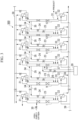
- FIG. 1 is a system diagram showing a main part of a stable isotope concentrating device according to an embodiment of the present invention.
- a stable isotope concentrating device 100 of the present embodiment includes a distillation column group in which a plurality of distillation columns are cascaded, a plurality of condensers 21, a plurality of reboilers 22, a raw material feed line 30 and a product line 31.
- the n-th distillation column from the upstream end of the distillation column group is referred to as the n-th distillation column.
- a 1st distillation column 1 to the n-th distillation column n are cascade-connected in the order of column numbers.
- the 1st distillation column 1 to the n-th distillation column n distill cooled stable isotopes at low temperature, and concentrate stable isotopes with a low boiling point on the top side of the column and stable isotopes with a high boiling point on the bottom side of the column.
- the 1st distillation column 1 to which the raw material is supplied has the largest column diameter, and the column diameter gradually decreases toward the end.
- the 1st distillation column 1 to the (j-1)-th distillation column j-1 are tray columns, and the j-th distillation column j to the n-th distillation column n are packing columns.
- the packing column group There are three possible configurations for the packing column group. Specifically, the three possible configurations are all random packing columns, the random packing columns are located on the secondary side of structured packing columns, and the structured packing columns are located on the secondary side of random packing columns.
- FIG. 1 only shows, among the 1st distillation column 1 to the n-th distillation column n, a 1 st distillation column 1 which is a tray column and a column in which the raw material stable isotopes are supplied, a j-th distillation column, which is the 1st column to change from the tray column to the packing column, and a n-th distillation column n, which is the column from which the product is collected.
- a 1 st distillation column 1 which is a tray column and a column in which the raw material stable isotopes are supplied
- a j-th distillation column which is the 1st column to change from the tray column to the packing column
- n-th distillation column n which is the column from which the product is collected.
- FIG. 1 shows a case in which only one distillation column in the random packing columns connected in parallel and one condenser and one reboiler are provided in one distillation column.
- the interval between trays is generally about 100 mm.
- the random packing column has H. E. T. P. of more than 100 mm, the height of the distillation column can be suppressed by using a tray column together. As a result, the number of distillation columns can be reduced, so that energy efficiency can be improved.
- the column diameter of the random packing column exceeds 200 mm, it is preferable to employ a tray column together. Furthermore, it is more preferable that the column diameter of the random packing column be 100 mm or less.
- the random packing column has a large hold-up amount.
- the tray column has a liquid layer at each stage, so the amount of hold-up is also large.
- the structured packing column generally has a small hold-up amount and can shorten the start-up operation time.
- the start-up operation time means the time until the concentration distribution is formed in the entire distillation column group. The effect of the hold-up amount on the start-up operation time becomes greater the closer to the "column from which the product is collected", in which the concentration degree from the natural abundance ratio is high.
- Mellapack manufactured by Sulzer Chemtech, is one of the structured packings that are often used in air separation equipment. H.E. T. P. thereof with a large specific surface area is about 150 mm to about 250 mm.
- the column diameter decreases from the upstream column to which the raw material is supplied to the downstream column which collects products, and most of the energy required is consumed by the upstream distillation columns.
- the number of distillation columns increases by adopting a structured packing column, but the start-up operation time can be greatly shortened. Also, since the column diameter of the increased distillation column is small, the drop in energy efficiency can be minimized.
- the tray column is adopted at least as the column to which the raw material is suppled, and the packing columns filled with the packing are adopted as columns other than the tray column.
- the packing column group has the following three configurations depending on the design conditions such as energy efficiency and start-up operation time.
- the interval between trays is preferably about 100 mm, and more preferably narrower than H. E. T. P. of the random packing.
- the 1st distillation column 1 to the (j-1)-th distillation column j-1 are tray columns
- the j-th distillation column j to n-th distillation column n are packing columns. That is, the stable isotope concentrating device 100 of the present embodiment includes a tray column group including one or more tray columns (1st distillation column 1 to (j-1)-th distillation column j-1), and a packing column group including one or more packing columns (j-th distillation column j to n-th distillation column n).
- the packing column group is located on the secondary side of the tray column group, and the packing column group may have any of the three configurations above according to design conditions.
- the tray column group includes the 1st distillation column 1 to which the raw material is supplied.
- the packing column group includes the n-th distillation column n from which the product is collected (derived).
- the 1st distillation column which serves as a recovery section, may be positioned before the column to which the raw material is supplied.
- the column from which the product is collected does not necessarily have to be the last column (n-th distillation column n), and may be in the middle of the distillation column group.
- the stable isotope concentrating device 100 of the present embodiment it is possible to increase the corresponding column diameter while maintaining high H. E. T. P. by connecting random packing columns in parallel.
- the same number of either the condenser or the reboiler can be installed as the number of columns connected in parallel, and only one unit of the other can be installed as a common device.
- the number of random packing columns connected in parallel is preferably 20 or less, more preferably less than 10, in order to reduce equipment costs and enable stable device operation.
- One or more condensers 21 are provided for each distillation column (1st distillation column 1 to n-th distillation column n).
- the condenser 21 is provided in a circulation line 32 of which ends are connected at different positions on the top of each distillation column.
- the condenser 21 has a function of liquefying gas that has ascended in the distillation column by exchanging heat and causing it to descend again in the distillation column.
- One or more reboilers 22 are provided for each distillation column.
- the reboiler 22 is provided in a circulation line 33 of which ends are connected at different positions on the bottom of each distillation column.
- the reboiler 22 has a function of exchanging heat with liquid that has descended in the distillation column to vaporize it and ascend the liquid in the distillation column again.
- the raw material feed line 30 is connected to the middle portion of the 1st distillation column 1.
- the raw material feed line 30 is a path for feeding the stable isotopes to the middle portion of the 1 st distillation column 1.
- a valve is provided in the raw material supply line 30.
- the middle portion of the distillation column refers to a position other than the top and bottom of the distillation column.
- the purity of the stable isotope supplied from the raw material supply line 30 is preferably as high as 99.999% or higher.
- a portion of vapor at the bottom in each distillation column which is concentrated in stable isotope with a high boiling point is supplied to the top of the next distillation column by a line 34 via a valve 23.
- the driving force of the flow is the pressure difference between the bottom of one distillation column and the top of the next distillation column.
- the vapor supplied to the top of the next distillation column is liquefied by the condenser 21 together with the ascending vapor in the distillation column, and is returned to the top of the distillation column.
- the product line 31 is a path for leading out the concentrated stable isotope component as a product from the n-th distillation column n.
- One end of the product line 31 is connected to a part near the bottom of the n-th distillation column n.
- the product is a stable isotope ingredient concentrated to a high concentration (e.g., 99% or more).
- the stable isotope concentrating device 100 of the present embodiment has the tray column group including one or more tray columns, and the packing column group including one or more packing columns, and the packing column group is located on the secondary side of the tray column group.
- the stable isotope concentrating device 100 of the present embodiment has high energy efficiency and can reduce equipment costs.
- the stable isotope concentrating device 100 of the present embodiment has an excellent balance between energy efficiency and start-up operation time.
- the tray column is adopted. As a result, the height of the distillation column can be reduced, further increasing energy efficiency.
- a tray column or a structured packing column may be adopted instead of the random packing column.
- the height of the distillation column can be suppressed similarly to the stable isotope concentrating device 100 of this embodiment, resulting in high energy efficiency.
- the tray column has a larger hold-up amount compared to that of the random packing column when the particle size of the random packing is large (the specific surface area of the packing is small). In this case, the start-up operation time is extended.
- H. E. T. P. is equivalent to that of the structured packing column filled with a packing having a large specific surface area.
- the energy efficiency is the same, but the start-up operation time can be shortened.
- the structured packing column may be adopted if it is a column near the column from which the product is collected, including the column from which the product is collected.
- the columns near the column from which the product is collected have a small column diameter, and the ratio of the energy required for operation to the total energy is small. Therefore, the decrease in energy efficiency is small, and the startup operation time can be greatly shortened.
- the number of the random packing columns connected in parallel is 20 or less, so the equipment cost can be further reduced.
- Example 1 a stable isotope concentrating device 200 shown in FIG. 2 was used to concentrate 18 O.
- the stable isotope concentrating device 200 has basically the same configuration as that of the stable isotope concentrating device 100.
- the distillation column group includes 12 distillation columns, a 1st distillation column 1 is a tray column, a 2nd distillation column 2 to a 12th distillation column 12 are random packing columns.
- Liquid nitrogen was used as a cold source for the condenser 21, and the liquid nitrogen was supplied to each condenser 21 from a liquid nitrogen supply line 38.
- Nitrogen gas was used as a heat source for the reboilers 22, and the nitrogen gas was supplied to each reboiler 22 from a nitrogen gas supply line 39.
- the stable isotope concentrating device 200 is provided with an isotope scrambler 20.
- An isotope-concentrated gas lead-out line 36 has one end connected to the middle portion of the 9th distillation column 9 and the other end connected to the isotope scrambler 20 in order to lead out some or all of the oxygen and supply the oxygen into the isotope scrambler 20.
- the oxygen that has undergone the isotope exchange reaction in the isotope scrambler 20 is returned to the middle portion of the 9th distillation column 9 through an isotope-concentrated gas return line 37.
- composition of the raw material high-purity oxygen to be supplied was as shown in Table 1.
- the interval of the trays in the 1st distillation column 1 was 100 mm.
- the column diameter per one distillation column was in the range of 100 to 200 mm.
- the column diameter per one distillation column was 100 mm or less.
- Table 2 shows the abundance of molecules including a stable isotope in the oxygen gas led out from the bottom of the 12th distillation column 12 when the apparatus is stable.
- Comparative Example 1 a stable isotope concentrating device 300 shown in FIG. 3 was used to concentrate 18 O.
- the stable isotope concentrating device 300 has basically same configuration as that of the stable isotope concentrating device 200 except that the number of the distillation columns is 13 and the 1st distillation column 1 is a packing column filled with random packing.
- the isotope scrambler 20 was connected to the middle portion of the tenth distillation column 10.
- composition of the raw material high-purity oxygen to be supplied was as shown in Table 1.
- the column diameter per one distillation column was 200 mm or more.
- the column diameter per one distillation column was 200 mm or less.
- the number of distillation columns connected in parallel was 20 or less in any distillation column group.
- Table 3 shows the abundance of molecules including a stable isotope in the oxygen gas led out from the bottom of the 13th distillation column 13 when the apparatus is stable.
- Example 1 the required heat exchange amount could be reduced by about 50% compared to Comparative Example 1, and the required number of the distillation columns could be reduced by 1 column. Moreover, in Example 1, it was possible to use only one condenser in the 1st distillation column 1.
- the stable isotope concentrating device of the present invention has high energy efficiency and can reduce equipment costs.
- one or more of the 2nd distillation column 2 to the 6th distillation column 6 may be a structured packing column.
- the total amount of heat exchange is approximately the same as that in Example 1, and the number of condensers in the 2nd distillation column 2 to the 6th distillation column 6 could be reduced to only one.
- the hold-up amount was small, it is expected that the start-up operation time will be shortened.
- Example 2 a stable isotope concentrating device 400 shown in FIG. 4 was used to concentrate 18 O.
- the stable isotope concentrating device 400 has 10 distillation columns, the 1st distillation column 1 to the 3rd distillation column 3 are tray columns, and the 4th distillation column 4 to the 10th distillation column 10 are random packing columns.
- the stable isotope concentrating device 400 has substantially the same configuration as that of the stable isotope concentrating device 200 except that the total number of distillation columns, the number of the tray columns, and the number of the packing columns are different.
- the isotope scrambler 20 was connected to the middle portion of the 7th distillation column 7.
- composition of the raw material high-purity oxygen to be supplied was as shown in Table 1.
- the interval of the trays in the 1st distillation column 1 to the 3rd distillation column 3 was 100 mm.
- the column diameter per one distillation column was 100 mm or less.
- the number of distillation columns connected in parallel was 10 or less in any distillation column group.
- Table 4 shows the abundance of molecules including a stable isotope in the oxygen gas led out from the bottom of the 10th distillation column 10 when the apparatus is stable.
- Example 2 when changing the 4th distillation column 4 from the random packing column to the tray column, the required length of the distillation column becomes longer, and it is necessary to increase the number of distillation columns. Therefore, there is no advantage to changing from a random packing column to a tray column.
- Example 3 a stable isotope concentrating device 500 shown in FIG. 5 was used to concentrate 18 O.
- the stable isotope concentrating device 500 has 13 distillation columns.
- the 1st distillation column 1 is a tray column.
- the 2nd distillation column 2 to the 11th distillation column 11 were random packing columns, and the 12th distillation column 12 and 13th distillation column 13 were structured packing columns.
- the stable isotope concentrating device 500 has substantially the same configuration as that of the stable isotope concentrating device 200 except that the total number of the distillation columns, the number of the tray columns, and the number of the packing columns are different.
- the isotope scrambler 20 was connected to the middle portion of the 9th distillation column 9.
- composition of the raw material high-purity oxygen to be supplied was as shown in Table 1.
- the interval of the trays in the 1st distillation column 1 was 100 mm.
- the column diameter per one distillation column was 200 mm or less.
- the number of distillation columns connected in parallel was 20 or less in any distillation column group.
- Table 5 shows the abundance of molecules including a stable isotope in the oxygen gas led out from the bottom of the 13th distillation column 13 when the apparatus is stable.
- Example 3 by using a structured packing column as distillation columns near the column from which the product is collected, the amount of heat exchange is about the same as that in Example 1, and the start-up operation time is reduced by about 20 days compared with Example 1.
- the stable isotope concentrating device of the present invention has an excellent balance between energy efficiency and start-up operation time.
- the results above can be obtained not only for oxygen but also for other stable isotopes.
- the stable isotope concentrating device of the present invention has high energy efficiency and reduces equipment cost.
- the present invention relates to a distillation device including a distillation column group in which a plurality of distillation columns are cascaded, and is used as a stable isotope concentrating device for concentrating stable isotope atoms that exist very rarely in nature.
Landscapes
- Chemical & Material Sciences (AREA)
- Chemical Kinetics & Catalysis (AREA)
- Separation By Low-Temperature Treatments (AREA)
- Vaporization, Distillation, Condensation, Sublimation, And Cold Traps (AREA)
- Treatment Of Liquids With Adsorbents In General (AREA)
- Medicinal Preparation (AREA)
Applications Claiming Priority (2)
| Application Number | Priority Date | Filing Date | Title |
|---|---|---|---|
| JP2020188709A JP7628807B2 (ja) | 2020-11-12 | 2020-11-12 | 安定同位体濃縮装置 |
| PCT/JP2021/039395 WO2022102390A1 (ja) | 2020-11-12 | 2021-10-26 | 安定同位体濃縮装置 |
Publications (2)
| Publication Number | Publication Date |
|---|---|
| EP4245403A1 true EP4245403A1 (de) | 2023-09-20 |
| EP4245403A4 EP4245403A4 (de) | 2024-10-09 |
Family
ID=81601130
Family Applications (1)
| Application Number | Title | Priority Date | Filing Date |
|---|---|---|---|
| EP21891637.7A Pending EP4245403A4 (de) | 2020-11-12 | 2021-10-26 | Vorrichtung zur konzentration stabiler isotope |
Country Status (6)
| Country | Link |
|---|---|
| US (1) | US12383864B2 (de) |
| EP (1) | EP4245403A4 (de) |
| JP (1) | JP7628807B2 (de) |
| CN (1) | CN115968317A (de) |
| IL (1) | IL301832A (de) |
| WO (1) | WO2022102390A1 (de) |
Families Citing this family (1)
| Publication number | Priority date | Publication date | Assignee | Title |
|---|---|---|---|---|
| CN115779681A (zh) * | 2022-12-05 | 2023-03-14 | 中国原子能科学研究院 | 一种碳的同位素的精馏系统 |
Family Cites Families (22)
| Publication number | Priority date | Publication date | Assignee | Title |
|---|---|---|---|---|
| CA2034740C (en) * | 1990-01-23 | 1995-03-21 | James Robert Dray | Cryogenic air separation system with hybrid argon column |
| US5019144A (en) * | 1990-01-23 | 1991-05-28 | Union Carbide Industrial Gases Technology Corporation | Cryogenic air separation system with hybrid argon column |
| US5197296A (en) * | 1992-01-21 | 1993-03-30 | Praxair Technology, Inc. | Cryogenic rectification system for producing elevated pressure product |
| JPH07148419A (ja) | 1993-11-29 | 1995-06-13 | Tomoshi Kitamoto | 酸素同位体の濃縮方法 |
| DE69833522T2 (de) * | 1997-10-13 | 2006-11-02 | Taiyo Nippon Sanso Corporation | Verfahren und Vorrichtung zur Trennung von Stabilisotopen |
| JP4214174B2 (ja) | 1998-04-01 | 2009-01-28 | 株式会社プレックス | 布展張装置 |
| WO2000027509A1 (en) * | 1998-11-09 | 2000-05-18 | Nippon Sanso Corporation | Method and apparatus for enrichment of heavy component of oxygen isotopes |
| JP4495279B2 (ja) * | 1999-10-12 | 2010-06-30 | 大陽日酸株式会社 | 蒸留装置並びに酸素同位体重成分の濃縮方法および重酸素水の製造方法 |
| JP2001208469A (ja) | 2000-01-28 | 2001-08-03 | Kobe Steel Ltd | 空気分離装置 |
| US7302812B2 (en) * | 2003-09-02 | 2007-12-04 | Air Products And Chemicals, Inc. | Process for production of isotopes |
| CN2675635Y (zh) | 2003-12-24 | 2005-02-02 | 上海化工研究院 | 用于富集重氧同位素水的水精馏装置 |
| JP5122443B2 (ja) | 2006-03-23 | 2013-01-16 | 大陽日酸株式会社 | 窒素同位体重成分の濃縮方法 |
| JP5026774B2 (ja) * | 2006-11-28 | 2012-09-19 | 大陽日酸株式会社 | 蒸留装置 |
| US20100025221A1 (en) * | 2008-07-31 | 2010-02-04 | Purdue Research Foundation | Process for distillation of multicomponent mixtures into five product streams |
| US8536384B2 (en) * | 2010-07-09 | 2013-09-17 | Celanese International Corporation | Recovering ethanol sidedraw by separating crude product from hydrogenation process |
| JP5132822B1 (ja) * | 2012-03-27 | 2013-01-30 | 大陽日酸株式会社 | 蒸留装置 |
| JP5813613B2 (ja) * | 2012-10-18 | 2015-11-17 | 大陽日酸株式会社 | 酸素同位体の濃縮方法 |
| AU2014234685B2 (en) | 2013-03-19 | 2019-04-18 | Linde Aktiengesellschaft | Method and device for generating gaseous compressed nitrogen. |
| DE102013018664A1 (de) | 2013-10-25 | 2015-04-30 | Linde Aktiengesellschaft | Verfahren zur Tieftemperaturzerlegung von Luft und Tieftemperatur-Luftzerlegungsanlage |
| EP3059536A1 (de) | 2015-02-19 | 2016-08-24 | Linde Aktiengesellschaft | Verfahren und Vorrichtung zur Gewinnung eines Druckstickstoffprodukts |
| JP7148419B2 (ja) | 2019-01-16 | 2022-10-05 | 株式会社エクセディ | ダンパ装置 |
| JP6913772B2 (ja) | 2020-01-09 | 2021-08-04 | 大陽日酸株式会社 | 安定同位体濃縮装置 |
-
2020
- 2020-11-12 JP JP2020188709A patent/JP7628807B2/ja active Active
-
2021
- 2021-10-26 EP EP21891637.7A patent/EP4245403A4/de active Pending
- 2021-10-26 US US18/252,517 patent/US12383864B2/en active Active
- 2021-10-26 CN CN202180051533.0A patent/CN115968317A/zh active Pending
- 2021-10-26 IL IL301832A patent/IL301832A/en unknown
- 2021-10-26 WO PCT/JP2021/039395 patent/WO2022102390A1/ja not_active Ceased
Also Published As
| Publication number | Publication date |
|---|---|
| JP7628807B2 (ja) | 2025-02-12 |
| IL301832A (en) | 2023-06-01 |
| WO2022102390A1 (ja) | 2022-05-19 |
| US12383864B2 (en) | 2025-08-12 |
| CN115968317A (zh) | 2023-04-14 |
| JP2022077733A (ja) | 2022-05-24 |
| EP4245403A4 (de) | 2024-10-09 |
| US20230405523A1 (en) | 2023-12-21 |
Similar Documents
| Publication | Publication Date | Title |
|---|---|---|
| JP2516680B2 (ja) | 酸素、窒素及びアルゴンを含む混合物の極低温分離法 | |
| CN1089427C (zh) | 用于生产低纯度氧的低温精馏系统 | |
| JP5122443B2 (ja) | 窒素同位体重成分の濃縮方法 | |
| KR960003270B1 (ko) | 증가된 압력으로 생성기체를 제조하기 위한 저온공기분리시스템 | |
| CN1103040C (zh) | 大气气体分离法 | |
| JP3256214B2 (ja) | 窒素を精製する方法及び装置 | |
| KR20000028773A (ko) | 고강도 및 고용량 패킹을 갖춘 극저온 정류 시스템 | |
| US12151208B2 (en) | Stable isotope concentration method | |
| US20230302407A1 (en) | Carbon stable isotope enrichment method | |
| US12383864B2 (en) | Stable isotope concentrating device | |
| KR100289109B1 (ko) | 공급 공기를 단계적으로 응축시키는 공기-비등 극저온 정류 장치 및 방법 | |
| CN1286387A (zh) | 生产甚高纯氧的低温精馏系统 | |
| JP6913772B2 (ja) | 安定同位体濃縮装置 | |
| KR20020027181A (ko) | 감소된 높이의 증류 칼럼용 구조적 충전 시스템 | |
| EP0798522A2 (de) | Kryogenisches Einsaulenrektifikationssystem zur Herstellung von niedrigreinem Sauerstoff | |
| CN1077276C (zh) | 分段进料空气冷凝的低温精馏系统 | |
| JP4319273B2 (ja) | 安定同位体化合物の分離方法及び装置 | |
| CN100368748C (zh) | 蒸馏设备以及增加蒸馏设备的容量的方法 | |
| CN1135351C (zh) | 生产氩的塔结构和氩的生产方法 | |
| KR19990082696A (ko) | 액체공기가연속공급되는극저온정류시스템 | |
| JP7512240B2 (ja) | 同位体分離装置の再起動方法 | |
| WO2025134560A1 (ja) | 空気分離装置 | |
| JPH04214174A (ja) | ハイブリッド型アルゴン塔による極低温精留方法及び装置 | |
| JP2022073512A (ja) | 安定同位体濃縮装置、及び安定同位体の濃縮方法 | |
| JP2001179002A (ja) | 複数充填カラム型蒸留塔及びこれを用いた高純度メタン製造方法 |
Legal Events
| Date | Code | Title | Description |
|---|---|---|---|
| STAA | Information on the status of an ep patent application or granted ep patent |
Free format text: STATUS: THE INTERNATIONAL PUBLICATION HAS BEEN MADE |
|
| PUAI | Public reference made under article 153(3) epc to a published international application that has entered the european phase |
Free format text: ORIGINAL CODE: 0009012 |
|
| STAA | Information on the status of an ep patent application or granted ep patent |
Free format text: STATUS: REQUEST FOR EXAMINATION WAS MADE |
|
| 17P | Request for examination filed |
Effective date: 20230216 |
|
| AK | Designated contracting states |
Kind code of ref document: A1 Designated state(s): AL AT BE BG CH CY CZ DE DK EE ES FI FR GB GR HR HU IE IS IT LI LT LU LV MC MK MT NL NO PL PT RO RS SE SI SK SM TR |
|
| DAV | Request for validation of the european patent (deleted) | ||
| DAX | Request for extension of the european patent (deleted) | ||
| A4 | Supplementary search report drawn up and despatched |
Effective date: 20240910 |
|
| RIC1 | Information provided on ipc code assigned before grant |
Ipc: B01D 3/14 20060101ALI20240904BHEP Ipc: B01D 59/04 20060101AFI20240904BHEP |