EP4245578A2 - Dispositif de détection d'attelage de véhicule tracteur ayant un entraîneur à friction - Google Patents
Dispositif de détection d'attelage de véhicule tracteur ayant un entraîneur à friction Download PDFInfo
- Publication number
- EP4245578A2 EP4245578A2 EP23181347.8A EP23181347A EP4245578A2 EP 4245578 A2 EP4245578 A2 EP 4245578A2 EP 23181347 A EP23181347 A EP 23181347A EP 4245578 A2 EP4245578 A2 EP 4245578A2
- Authority
- EP
- European Patent Office
- Prior art keywords
- driver
- coupling
- particles
- driving
- rotation
- Prior art date
- Legal status (The legal status is an assumption and is not a legal conclusion. Google has not performed a legal analysis and makes no representation as to the accuracy of the status listed.)
- Withdrawn
Links
Images


Classifications
-
- B—PERFORMING OPERATIONS; TRANSPORTING
- B62—LAND VEHICLES FOR TRAVELLING OTHERWISE THAN ON RAILS
- B62D—MOTOR VEHICLES; TRAILERS
- B62D53/00—Tractor-trailer combinations; Road trains
- B62D53/04—Tractor-trailer combinations; Road trains comprising a vehicle carrying an essential part of the other vehicle's load by having supporting means for the front or rear part of the other vehicle
- B62D53/08—Fifth wheel traction couplings
-
- B—PERFORMING OPERATIONS; TRANSPORTING
- B60—VEHICLES IN GENERAL
- B60D—VEHICLE CONNECTIONS
- B60D1/00—Traction couplings; Hitches; Draw-gear; Towing devices
- B60D1/01—Traction couplings or hitches characterised by their type
- B60D1/06—Ball-and-socket hitches
-
- B—PERFORMING OPERATIONS; TRANSPORTING
- B60—VEHICLES IN GENERAL
- B60D—VEHICLE CONNECTIONS
- B60D1/00—Traction couplings; Hitches; Draw-gear; Towing devices
- B60D1/58—Auxiliary devices
- B60D1/62—Auxiliary devices involving supply lines, electric circuits or the like
Definitions
- the invention relates to a sensor device for a towing vehicle coupling or as a component of a towing vehicle coupling, with which a trailer vehicle, in particular a semi-trailer, can be coupled to a towing vehicle, in particular a truck, the towing vehicle coupling having a coupling element for releasably coupling a coupling counterpart element which is on the towing vehicle and the trailer vehicle are fastened or can be fastened and, in the coupled state, forming a joint can be rotated relative to one another about at least one joint axis of rotation, the sensor device being rotatably mounted with respect to the coupling element about a driving axis of rotation and being supported by the coupling counter element during a rotation about the at least a joint axis of rotation about the driving axis of rotation rotatable driver for detecting a rotation of the dome counter element relative to the coupling element about the at least one joint axis of rotation, wherein the driver has at least one friction surface for a frictional contact with the dome counter element
- Such a sensor device is, for example, in EP 2 415 620 A1 described.
- the driver is designed as a ring which is rotatably mounted on the outer circumference of a coupling element designed as a ball head.
- the coupling counter element is a ball head receptacle, a so-called ball socket, which is placed on the coupling ball and thus the coupling element and rotates the driver.
- flexible driving projections protrude in front of the driver, which are compressed in a certain way when the dome counter element, namely its closing jaw, is closed, so that a frictional connection is realized between the dome element and the driver.
- a sensor device of the type mentioned at the outset provides that a plurality of particles are arranged on the at least one frictional surface for contact with the dome counter-element and/or that it has a counter-driver element which is arranged or can be arranged on the dome counter-element, which for Contact with the friction surface of the driver has a driving surface with a large number of particles.
- the coupling element is attached or attachable to the towing vehicle and the coupling counter element is attached or attachable to the trailer vehicle. It is also possible for the coupling counter element to be attached or attachable to the towing vehicle and the coupling element to be attached or attachable to the trailer vehicle.
- the coupling element and the coupling counter element are coupled to one another, the coupling element and the coupling counter element are rotatable relative to one another about at least one joint axis of rotation and form a joint.
- the friction surface of the driver it is therefore possible on the one hand for the friction surface of the driver to have a large number of particles, but on the other hand also for a large number of particles to be present on the counter-driver element. It is possible that particles are only provided on one of the drivers or counter-driver elements. But it is also possible that on both, the driver and the Counter-driver element, particles are provided which support the rotational drive of the driver by the dome counter-element. The measures explained below, which are advantageous for the friction surface of the driver or are useful for the design of the particles, can easily also be present in the counter-driver element.
- the dome counter element is a kingpin
- particles are advantageously provided, for example, on its end face facing the driver.
- a part can also be provided on a spherical receptacle for a coupling element in the form of a spherical head, which is designed as a counter-driver element or has a counter-driver element and accordingly comprises particles.
- the counter-drive element can, for example, be flexible and/or film-like.
- the counter-drive element can be designed, for example, as a plate body, which can be fastened, in particular releasably, to the coupling element or coupling counter element.
- an adhesive surface for sticking to the dome counter element is provided on the counter-drive element.
- the counter-drive element has a base body made of elastic plastic, rubber or the like.
- the particles are embedded in the base body or the particles are integrated into the base body.
- the counter-drive element can, for example, be glued, welded or otherwise attached to the dome counter element. Fastening using screws, rivets or the like is also easily possible.
- the counter-drive element can be designed as a friction body on which particles are arranged for rotational driving or for contact with the driver.
- the particles of the counter-drive element are preferably embedded in a friction surface, for example elastic plastic, rubber or the like.
- the counter-driver element can form an integral part of the dome counter-element, which is intended to drive the driver in rotation.
- the particles can be embedded in a surface material of the dome counter element.
- the particles do not lead to damage to the dome counter-element, since the driver and the dome counter-element are not or only slightly movable relative to one another due to the high friction that can be achieved by the particles. Natural or existing irregularities or inaccuracies in the counter-dome element can, so to speak, lead to increased friction between the driver and the counter-dome element if the particles penetrate these irregularities.
- the particles are preferably harder than steel.
- the dome counter-element is generally also made of metal, in particular steel, entirely or at least in the area of a driving surface which is intended for contact with the frictional surface of the sensor device.
- a friction pairing that has high friction.
- dirt, grease or the like can easily be displaced into spaces between the particles, so that the particles protrude with their tips or edges in front of the "fat layer” or “dirt layer” and dig into the surface of the dome counter element to a certain extent penetrate into this.
- the dome counter element can easily consist of metal, in particular steel or the like. Even this material has a certain basic surface roughness into which the particles of the driver at least partially penetrate. This advantageously results in its positive rotational driving.
- the particles are preferably particularly small.
- a grain size or particle size is only about 1800-500 ⁇ m.
- the particles can also be even smaller, for example smaller than 500 ⁇ m.
- even smaller particles with, for example, a maximum of 200 ⁇ m or a maximum of 100 ⁇ m can be provided.
- Even smaller particles for example, have a grain size or particle size of 25-50 ⁇ m or even just between 8 and 25 ⁇ m.
- the particles are preferably polyhedra.
- Polyhedral sections of the particles preferably protrude in front of the support surface of the driver that supports them.
- the particles as a whole or the sections of the particles that protrude in front of the supporting surface include, for example, tetrahedrons and/or pentahedrons and/or hexahedrons and/or heptahedrons and/or octahedrons and/or enneahedra and/or decahedrons and/or hendecahedrons and/or tridecahedrons and /or tetradecahedron and/or disheptahedron and/or pentadecahedron and/or hexadecahedron and/or heptadecahedron and/or octadecahedron and/or enneadecahedron.
- this list is not exhaustive.
- the particles are, for example, embedded in a supporting surface of the driver and protrude in front of the supporting surface in the manner of contact projections.
- a partial section of a respective particle is firmly anchored in the supporting surface, while another part forms a contact projection for contact with the dome counter element.
- the particles can, for example, be embedded in an elastic material, for example an elastic layer or an elastic base body, of the driver.
- the particles protrude in front of the elastic material in the manner of contact projections. This means that the particles can move somewhat in the direction of the elastic material when the driving contact between the dome counter element and the driver is established.
- the elastic layer acts on the particles in the direction of the dome counter element or in the direction of frictional contact with it.
- the particles are comparatively hard compared to a material that supports them. It is preferably provided that the particles are harder than a material of the driver that supports them, for example a plastic material. The particles protrude in front of the material.
- the hardness of the particles is, for example, twice or three times, but preferably four times or five times, greater than that of the material carrying the particles.
- the particles can also be even harder, for example up to ten or a hundred times harder than the driver material that supports them.
- the particles can protrude freely in front of a supporting surface of the driver on which they are arranged.
- the particles can be covered by a cover layer on their side facing away from the supporting surface or on the side facing the dome counter-element or for driving contact with the dome counter-element.
- a cover layer on their side facing away from the supporting surface or on the side facing the dome counter-element or for driving contact with the dome counter-element.
- calcium stearate, a wax or the like is suitable for covering the particles. Nevertheless, their generally hard edges and/or tips can protrude in front of this cover layer, so that contact of the particles with the dome counter element can be easily achieved.
- the driver can, for example, be rotatably mounted directly on the coupling element. However, it can also be mounted on a coupling element carrier, e.g. a coupling arm. Furthermore, it is possible for the driver to be rotatably mounted away from the coupling element on a bearing body which is separate from the coupling element and/or its coupling element carrier.
- a multi-part, especially two-part, design of the driver is also advantageous: It is preferred if the driver has a driver carrier to which a driver body is releasably attached.
- the at least one frictional engagement surface or an arrangement of several frictional engagement surfaces with particles is provided on the driving body.
- the driver carrier is, for example, on the coupling element, the bearing element that is separate from the coupling element or the like rotatably mounted.
- the driver body itself is the wearing part that can be replaced if necessary. Even if the sensor device is supposed to be inactive, so to speak, this solution offers advantages.
- the driving body can be removed from the driving carrier so that the driving carrier cannot have driving contact with the dome counter-element.
- the driver carrier forms, so to speak, the rotatably mounted component, while the driver body is attached to the driver carrier, for example locked, glued, clipped, screwed or otherwise attached.
- the driver in particular the driver carrier, can, for example, form a protective housing for the at least one sensor and/or an evaluation device of the sensor.
- the driver in particular the driver body, expediently has a sliding slope for sliding on the dome counter element.
- the coupling counter element cannot damage the driving body when coupling the coupling counter element to the coupling element or easily come into driving contact with the driving body.
- the sliding slope for the dome counter element is preferably provided on an edge region of the driving body.
- the driver body can surround the driver carrier in a ring. This variant is particularly advantageous when the driving body is arranged directly on the coupling element, in particular a coupling ball.
- the driver body forms a cover cap or a lid for the driver carrier.
- the friction surfaces are then arranged on the front side and/or radially on the outside of the driving body.
- driver body protrudes in front of the driver carrier in the manner of a mushroom or the like. It is preferred, for example, if the driving body projects transversely to the driving axis of rotation in front of the driving carrier.
- the friction surface that has the particles is penetrated, for example, by the driving axis of rotation.
- the friction surface with the particles it is also possible for the friction surface with the particles to be arranged radially on the outside with respect to the driving axis of rotation.
- the driving body expediently has at least one magnet for generating a magnetic attraction in the direction of the dome counter element.
- the magnet can, for example, be arranged next to, in particular below, the driving body. It is preferred if the magnet is arranged on the driving body or is accommodated in the driving body. Therefore, for example, a magnet or an arrangement of several magnets is embedded in the driving body.
- the magnet can, for example, be arranged on an end face of the driving body. For example, the driving axis of rotation passes through the magnet.
- the frictional engagement surface with the particles or a frictional engagement surface with the particles can be arranged directly on the magnet, in particular on its flat side or end face.
- the particles expediently have a large number of regularly or irregularly oriented edges.
- the particles can, for example, be arranged chaotically or randomly on the friction surface.
- irregularly oriented edges appear.
- irregularly oriented edges can also arise because the particles are obtained from a solid material that is broken. Particularly if the material does not have a crystalline structure, chaotic or irregular edges are formed when broken.
- the edges can also arise, for example, due to a crystalline structure of the material of the particles.
- the particles can, for example, be arranged openly scattered on the friction surface or can also be scattered closed. In open scattering, gaps are present between the particles, so that, for example, a supporting surface between the particles is at least partially exposed.
- the closed scattered particles are so close together that between there are no open spaces or free sections of the supporting surface that carry the particles.
- the friction surface can have zones with different particle densities.
- edge zones or radially outer zones of the friction surface can have a higher density of particles than radially inner zones with respect to the driving axis of rotation.
- the friction surface can have at least one area without particles.
- the frictional engagement surface can have a support surface made of rubber or similar other frictional material, which can independently produce a frictional engagement with the dome counter element.
- the particles can be provided on zones of the friction surface that are spaced apart from one another.
- the zones can, for example, have an angular distance or a radial distance from one another, or both.
- ring segments can be provided which extend around the driving axis of rotation. Even if frictional surfaces with particles are provided radially on the outside with respect to the driving axis of rotation, i.e. on a radial outer circumference of the driver or the driver body, distances can be provided between these frictional surface zones, in particular if the frictional surfaces are on driving projections in the type of driver according to EP 2 415 620 A1 are arranged.
- an envelope of the particles defining the contact area with the dome counter element is a planar surface or flat surface. This is advantageous, for example, with a dome counter-element in the form of a kingpin or the like.
- the envelope can also be a spherical segment surface, for example if the dome counter element comprises a ball socket or a spherical receptacle.
- At least one form-fitting contour for example a driving projection, is preferably arranged on the driver for a form-fitting contact with the dome counter element.
- the driver preferably has an arrangement of several driver projections. This means that both a positive connection and a frictional connection between the driver and the dome counter element can be achieved.
- the at least one positive locking contour or the at least one driving projection is preferably at least five times larger, in particular at least ten times, at least 20 times or at least 30 times, particularly preferably at least 100 times larger than the particles that are arranged on the positive locking contour or the driving projection.
- the positive locking contour for example a locking contour
- the positive locking contour expediently has a frictional contact surface with a large number of particles for contact with the dome counter element.
- a combination of positive locking contours with and without particles on their respective contact surfaces for the dome counter element is also possible.
- driving projections with and without particles can be provided, for example alternately next to one another or at irregular intervals.
- the driver preferably has at least two, preferably a plurality, driving projections which protrude in front of a base body of the driver and which are at a distance from one another, for example an angular distance or a longitudinal distance or both.
- At least one driving projection is provided with a friction surface with a large number of particles on one end face for contact with the dome counter element.
- the driving projections can, for example, be oriented radially on the outside with respect to the driving axis of rotation.
- the driver expediently has at least one elastic or resilient section for elastic or resilient deformation by the dome counter element.
- This elastic section can, for example, be the one on which the friction surface is arranged and the particles are present are. However, it is also possible for the elastic section to be provided in a layer on which a support layer for the particles is provided.
- the sensor device has a magnet arrangement for providing a magnetic attraction force acting on the driver in the direction of the dome counter element.
- the magnet arrangement can comprise one or more magnets, which cooperate, for example, with the ferromagnetic dome counter element.
- the magnet arrangement can include permanent magnets and/or electromagnetically acting magnets.
- the magnet arrangement includes one or more electrical coils.
- the magnet arrangement can have one or more flux guiding elements for directing the magnetic flux generated by a permanent magnet or electromagnet of the magnet arrangement.
- a flux guide element in particular a soft magnetic flux guide element, is designed and provided to direct or guide the magnetic flux in the direction of the dome counter element.
- the flow guide element is, for example, suitable for reinforcing or aligning an attractive force of the driver in the direction of the dome counter-element.
- the magnet arrangement can be designed or arranged to actuate and excite the at least one sensor.
- the magnet arrangement is therefore used twice, so to speak, namely on the one hand for generating the attractive force in the direction of the dome counter element, but on the other hand also for exciting or actuating the at least one sensor.
- the magnet arrangement can have a shielding device for shielding the at least one sensor from magnetic influences of the magnet arrangement.
- the magnetic field of the magnet arrangement can be directed away from the sensor or around the sensor.
- the magnetic flux or the magnetic field of the magnet arrangement can be directed around a partial area of the sensor in order to avoid incorrect operation, although the magnetic field is still directed in the direction of the sensor, but at a different location.
- the driver can have a driver ring or annular section. Several partial rings that are coupled or connected to one another can also be present in the driver. An annular or partially annular circumferential driving contour on the driver is also advantageous.
- the driver expediently has a dome-like or tower-like driving body.
- the driving body can be designed, for example, in the form of a hood or a cover.
- the sensor device expediently comprises at least one sensor or sensor transmitter which is rotatably mounted about the driving axis of rotation, in particular a ring which comprises an arrangement of several sensors or sensor transmitters.
- the rotatably mounted sensor or sensor transmitter is rotatably coupled or rotatably connected to the driver. So when the driver rotates around the driving axis of rotation, it takes the at least one sensor or sensor transmitter with it.
- particles of different types can be present on the friction surface, meaning that mixtures and combinations of the particle variants presented below are easily possible: At least some of the particles expediently have a crystalline structure or are mineral.
- the particles can also be made of a rock material.
- the particles are produced by breaking or squeezing a hard base material, for example a rock material or quartz.
- the particles may comprise or be formed by one or more of the following materials: It is preferably provided that the particles contain metal, in particular metal chips or metal particles, and/or ceramic material and/or rock material and/or sand and/or corundum and/or quartz and/or diamonds and/or cubic boron nitride and/or aluminum oxide or are thereby formed.
- the sand is preferably broken sand or crushed sand.
- the particles may include or be formed by silicon carbide or silicon.
- the aforementioned fundamentally hard materials can be comminuted, whereby the particles are formed.
- the particles can be metallic and/or comprise metal particles.
- the particles can preferably comprise, for example, hard metal granules or be formed thereby.
- the particles can also include or be formed by metal chips.
- the particles can also include or be formed by so-called blasting media, which are suitable, for example, for blasting workpieces.
- the particles preferably include or are formed by corundum. Natural corundum, precious corundum, normal corundum, electrocorundum, aluminum oxide (Al 2 O 3 ) may be mentioned as examples. But other corundums, for example so-called white corundum and brown corundum, are also suitable for the particles.
- the particles can advantageously comprise, for example, zirconium corundum or be formed thereby.
- This has a microcrystalline structure which, when subjected to wear, for example due to force, friction or the like the dome counter element, repeatedly releases sharp breaking edges. This creates a self-sharpening effect, so to speak.
- the particles can be, for example, iron (III) oxide (Fe 2 O 3 ) and/or sodium oxide (Na 2 O) and/or calcium oxide (CaO) and/or silicon dioxide (SiO 2 ) and/or titanium (IV) oxide or titanium dioxide (TiO 2 ) include or be formed thereby.
- the friction surface can also include particles obtained from melting chamber slag, for example by breaking it.
- the melting chamber slag or the particles obtained from it are preferably angular.
- the melting chamber slag and/or the particles obtained from it can contain iron or be iron-free.
- the particles can also be made of glass or contain glass.
- the particles contain, in particular, angular glass granules and/or glass beads or are formed thereby.
- Hard plastics are also suitable for the particles.
- the particles can comprise or be formed by plastic granules, in particular sharp-edged plastic granules.
- the plastic granulate can be or comprise, for example, a thermoset plastic granulate and/or a polyamide plastic granulate and/or a polycarbonate plastic granulate.
- the particles can also be very fine-grained or small.
- the particles may include calcite powder, glass powder, stone powder or the like.
- the particles can, for example, be glued to a carrier material of the driver with glue, in particular natural glue, and/or with synthetic resin.
- glue in particular natural glue, and/or with synthetic resin.
- a so-called natural glue bond or synthetic resin bond, in particular a full synthetic resin bond, of the particles with the carrier material is easily possible.
- Natural glue is used for the basic binding and synthetic resin is used for the top binding.
- the driver is movably mounted with respect to the coupling element in order to provide or maintain a driving coupling to the coupling counter element with at least one degree of freedom of movement, in particular at least one degree of rotational freedom, which is different from the rotatability about the driving axis of rotation.
- a basic idea here is that the driver is not only rotatable about the driving axis of rotation with respect to the ball element, but also by one or more further degrees of freedom of movement, which differ from the rotatability about the driving axis of rotation or the degree of rotation about the driving axis. Differentiate the axis of rotation. As a result, the driver can, so to speak, be brought into floating contact or driving coupling with the dome counter element, for example a ball coupling.
- the driver can be mounted directly on the coupling element.
- a bearing holder for the driver in particular a bearing groove, is provided on the coupling element.
- the driver is rotatably mounted about the driving axis of rotation on a bearing body that is separate from the coupling element.
- the bearing body is suitable, for example, for retrofitting an existing trailer coupling or towing vehicle coupling.
- a preferred exemplary embodiment provides that the coupling element is a coupling ball and the coupling counter element is a coupling receptacle of a tow coupling of a trailer.
- the coupling element designed as a coupling ball expediently protrudes in front of a coupling arm or is arranged at a free end region of a coupling arm.
- the sensor device is arranged or can be arranged on a so-called fifth wheel coupling, in which the coupling element is a Coupling receptacle, for example a coupling mouth for receiving a saddle pin of the dome counter element.
- the receptacle is therefore provided on the towing vehicle, while the component engaging in the receptacle is present on the trailer vehicle.
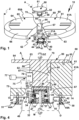
- a towing vehicle coupling 60 is designed as a fifth wheel coupling 60A.
- the fifth wheel coupling 60A has a coupling element 61 in the form of a so-called mounting plate 61A.
- An insertion receptacle 62 which can also be referred to as an insertion opening, is provided on the mounting plate 61A and therefore on the coupling element 61.
- the insertion receptacle 62 facilitates the insertion of a coupling counter element 81 of a trailer coupling 80, which has a so-called pin 82 or saddle pin 82.
- the pin 82 is used to couple the trailer coupling 80 to the towing vehicle coupling 60, the coupled state being in the Figures 2-8 is shown.
- the towing vehicle coupling 60 is arranged or can be arranged on a towing vehicle Z.
- the towing vehicle Z is, for example, a so-called semi-trailer or other truck.
- the trailer coupling 80 is attached or can be attached to a trailer A, for example a so-called semi-trailer.
- the saddle pin or pin 82 is brought, for example, from a rear side of the towing vehicle Z or from an end face 63 of the coupling element 61 to the coupling element 61, whereby in practice the towing vehicle Z drives backwards around the semi-trailer and thus to couple trailer A.
- the trailer vehicle A is supported on a top side 83 of the trailer coupling 80 or the pin 82.
- the top 83 is, for example, connected to an underside of the trailer A, for example welded or screwed.
- the top 83 is provided on a flange body 84, the underside of which facing away from the top 83 forms a support surface 85 for support on the towing vehicle coupling 60.
- the support surface 85 serves to rest on a support surface 65 on the top 64 of the mounting plate 61A or the coupling element 61.
- the support surface 65 and the support surface 85 are preferably flat surfaces.
- the trailer coupling 80 is therefore supported over a large area on the support surface 65 in a horizontal plane, so that significant supporting forces do not act on the actual fifth wheel pin 82, which namely engages with a pin section 91 in a coupling receptacle 70 of the towing vehicle coupling 60.
- a sliding slope 66 is arranged on the end face 63, along which the support surface 85 can slide along when coupling the trailer coupling 80 to the towing vehicle coupling 60.
- the insertion of the saddle pin 82 into the coupling receptacle 70 is facilitated by insertion bevels 68, which laterally delimit the insertion receptacle 62 and extend towards the coupling receptacle 70 towards one another in the sense of a narrowing.
- the insertion bevels 68 extend from the end face 63 towards a front side 69 of the coupling element 61 or the mounting plate 61A.
- the coupling receptacle 70 has a substantially cylindrical inner contour 71, whereby this inner contour 71 does not have to be completely cylindrical, but rather merely represents an enveloping inner contour, so to speak.
- the pin section 91 is therefore at least partially supported with its essentially cylindrical outer circumferential contour 86 on the inner circumference of the coupling receptacle 70, so that the saddle pin 82 can rotate essentially about a joint axis of rotation GZ relative to the towing vehicle coupling 60.
- a support body 72 is arranged on an underside 74 of the coupling element 61 or the mounting plate 61A.
- the support body 72 is provided next to and/or below the coupling receptacle 70.
- the support body 72 can be plate-like.
- the fifth wheel pin 82 is to be inserted past the support body 72 into the coupling receptacle 70 when the trailer coupling 80 is coupled to the towing vehicle coupling 60.
- the coupling element 61 is preferably reinforced on its underside 74 by a rib structure or by ribs 73, which makes the support surface or support surface 65 particularly resilient.
- the trailer coupling 80 can be locked to the towing vehicle coupling 60 by a locking device 75 of the towing vehicle coupling 60.
- the locking device 75 comprises a locking body 76, which engages in a locking receptacle 87 of the pin 82, which is provided on its outer circumference 86.
- the pin 82 can be easily inserted into the coupling receptacle 70, for example by having a sliding slope 89 on its end face 88, i.e. on the side of the pin 82 opposite the flange body 84.
- the sliding slope 89 is provided, for example, by a rounded or conical edge section between the outer circumference 86 and the end face 88 or end face of the pin 82.
- the locking body 76 can expediently be driven by a manual or motorized locking drive 77 so that it is in its locking position engages in the locking receptacle 87 and is moved out of the locking receptacle 87 in its release position, so that the pin 82 can be moved out of the coupling receptacle 70.
- the trailer coupling 80 can preferably rotate with respect to the towing vehicle coupling 60 about the joint axis of rotation GZ, i.e. about an axis of rotation that is generally approximately vertical during driving, but also about joint axes of rotation GX and GY, i.e. about a longitudinal axis and a transverse axis, which run in particular in the longitudinal direction of the towing vehicle Z or orthogonally at right angles to the longitudinal direction of the towing vehicle Z.
- the joint axis of rotation GZ i.e. about an axis of rotation that is generally approximately vertical during driving
- joint axes of rotation GX and GY i.e. about a longitudinal axis and a transverse axis, which run in particular in the longitudinal direction of the towing vehicle Z or orthogonally at right angles to the longitudinal direction of the towing vehicle Z.
- the coupling counter element 81 can rotate or pivot relative to the coupling element 61 with respect to the joint rotation axes GX, GY and GZ, so that the coupling element 61 and the coupling mating element 81 form a joint 95.
- the dome counter element 81 and the dome element 61 are in bearing engagement with one another in a storage area 96.
- the storage area 96 is preferably approximately cylindrical.
- the trailer vehicle A when cornering, can pivot relative to the towing vehicle Z essentially about the joint axis of rotation GZ.
- the trailer vehicle A can also pivot or rotate relative to the towing vehicle Z during a rolling movement or rolling movement about the joint axis of rotation GX and/or during a pitching movement about the joint axis of rotation GY.
- the sensor device 10 is accommodated in a receiving space 67 below the coupling receptacle 70.
- the receiving space 67 is a receiving space that is already present in a standard fifth wheel coupling 60A, ie a structural modification is not necessary.
- the sensor device 10 is intended to be rotated by the dome counter element 81, which has a driving surface 90 for this purpose.
- the driving surface 90 is formed, for example, by the end face 88 or is provided on it. But the sliding slope 89 or another area of the outer circumferential contour 86 can also form the driving surface 90 in whole or in part, which becomes even clearer.
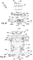
- the sensor device 10 has a driver 20, which can be carried along by the dome counter element 81, namely the pin or saddle pin 82, and can be rotated about a driving axis of rotation M.
- the driver 20 has a driving surface 21 for producing a driving contact or a driving connection with the pin 82.
- the driving surface 21 is provided on a free end face of the driver 20.
- a peripheral wall 22 extends away from the driving surface 21 and is, for example, essentially conical or cylindrical.
- the driving surface 21 is provided on an end wall 21A, which is essentially designed as a flat or flat wall.
- the peripheral wall 22 extends away from the end wall 21A.
- annular driving contour can also be provided on a driver according to the invention.
- annular peripheral driving contour 27 in particular a ring, is provided, which can be in engagement with at least a portion of the outer circumference 86 of the pin 82.
- the circumferential driving contour 27 can be partially annular, for example comprising one or more driving projections which protrude towards the pin 82.
- the driver body 20A is preferably elastically deformable in the area of the driving surface 21 and/or the peripheral driving contour 27 and has an elastic section 28 there.
- the driver body 20A consists of an elastic, deformable plastic or rubber, at least in the elastic section.
- a side of the driver 20 opposite the end wall 21A is essentially closed by a bottom wall 23, so that a substantially encapsulated or protective interior 29A is formed.
- the end wall 21A and the peripheral wall 22 form components of a driver body 20A.
- the driver body 20A is dome-like or hood-like and is, so to speak, closed on the bottom side by the bottom wall 23.
- the driver body 20A and the bottom wall 23 essentially encapsulate an interior space 29A. This creates a protective housing 29.
- the protective housing 29 protects the components arranged in its interior 29A and explained in detail below.
- the sensor device 10 includes a sensor 11, for example a magnetic sensor, which is arranged in the interior 29A. Signals generated by the sensor 11 are evaluated by an evaluation device 12, which includes, for example, a processor 13 and a memory 14.
- the processor 13 executes program code from at least one program, which processes the sensor signals of the sensor 11 and, for example, provides them to an interface 15, in particular a bus coupler, for an on-board network N of the towing vehicle Z.
- the interface 15 is, for example, a CAN bus interface, but can also easily be or include another digital or analog interface.
- the evaluation device 12 is arranged, for example, on or in a housing 16.
- a circuit board or similar other carrier for electronic components for example the processor 13 or the memory 14 or both, can also be provided.
- the evaluation device 12 as a whole, including the sensor 11, is protected in the interior 29A, ie in the driver body 20A.
- the sensor carrier 24 is arranged in a rotationally fixed manner on the inside of the peripheral wall 22, i.e. inside the driver body 20A.
- the sensor carrier 24 has a substantially annular shape. On its inner circumference, opposite the sensor 11, the sensor carrier 24 has sensor element receptacles 26 for the sensor transmitters 25.
- the sensor transmitters 25 and the sensor element receptacles 26 are arranged in a ring around the driving axis of rotation M of the driver 20 and form a ring arrangement 25B.
- the sensor transmitters 25 are rotated past the sensor 11, whereby a high level of measurement accuracy can be achieved.
- the sensor device 10 in particular the evaluation device 12, is connected to the vehicle electrical system N via a line arrangement VX connected to the interface 15.
- VX connected to the interface 15.
- a wired connection of the sensor device 10 to the vehicle electrical system N is therefore realized, as in the exemplary embodiment to be explained Figures 9, 10
- a wireless connection is also possible, for example via infrared, radio or the like.
- the driver 20 is rotatably mounted on a bearing body 30 about the driving axis of rotation M.
- the bearing body 30 is designed, for example, as a bearing shaft or bearing axle.
- the bearing body 30 has a flange projection 31 on which a pivot bearing 33 is held.
- a further pivot bearing 34 is provided, which is supported on the bearing body 30 by means of a support body 39.
- the rotary bearings 33, 34 are preferably rolling bearings, in particular ball bearings, roller bearings or the like, which is why the driver 20 rotates smoothly about the driving axis of rotation M.
- the bearing body 30 is held in a rotationally fixed manner with respect to the driving axis of rotation M by means of an anti-rotation device 35 on a holding device 40, which is provided for holding the sensor device 10 on the towing vehicle coupling 60.
- the holding device 40 has a holding plate 41 on which the bearing body 30 is supported or in front of which the bearing body 30 protrudes.
- the holding plate 41 forms a carrier 47 for the bearing body 30.
- the anti-rotation device 35 includes a screw 36 which is screwed into a screw receptacle 36A.
- the screw 36 penetrates a screw opening on the holding plate 41, which is eccentric to the driving axis of rotation or central axis of the bearing body 30.
- the bearing body 30 has an elongated shape extending along the driving axis of rotation. A distance is provided between the pivot bearings 33, 34 in which the sensor 11 is arranged.
- the rotary bearings 33, 34 which are spaced apart from one another or spaced apart from one another, offer optimal support of the driver 20 on the bearing body 30 with respect to the driving axis of rotation M, so that the driver 20 is optimally supported transversely to the driving axis of rotation M.
- the bearing body 30 also has a receiving space 30A for the sensor 11 and the evaluation device 12.
- a channel 37 for the lines of the line arrangement VX runs from the receiving space A and opens out at the holding plate 41.
- a passage opening 46 is provided there for the line arrangement VX, through which the lines of the line arrangement VX are guided.
- the line arrangement VX includes, for example, a data connection DV, which includes one or more bus lines. Furthermore, supply connections V1, V2, for example a low direct voltage of 5-10 volts and ground, are components of the line arrangement VX.
- the driver 20 is movably mounted with respect to the coupling element 61, in particular the coupling receptacle 70, so that it, so to speak, follows different movements from the driving axis of rotation M, particularly when coupling the trailer coupling 80 to the towing vehicle coupling 60.
- the sliding slope 89 can move the driver 20 out of its position and into it Figures 4 and 5 position shown, in which the driving axis of rotation M with the joint axis of rotation GZ is, so to speak, aligned or parallel to it, deflected so that the driver 20 can be deflected from its central position by rotational degrees of freedom DX and DY and / or linear degrees of freedom of movement LX, LY and LZ.
- the pivoting degrees of freedom or rotational degrees of freedom DX, DY run orthogonally to the driving rotation axis M and each orthogonally to one another.
- the driver 20 can pivot with the rotational degree of freedom DX about an axis SX that is parallel to the joint rotation axis GX.
- the driver 20 can be deflected linearly about the axis SX, which is parallel to the joint axis of rotation GX, i.e. moved at right angles to the driver axis of rotation M.
- the further linear degree of freedom of movement LY allows a deflection or displacement of the driver 20 transversely to the degree of freedom of movement LX or to the X-axis and/or along an axis SY which is parallel to the joint axis of rotation GY.
- the driver 20 rotates about this axis SY, which is parallel to the joint rotation axis GY.
- the displaceability with the degree of freedom of movement LZ is provided parallel or coaxial to the driving axis of rotation M, e.g. about an axis SZ.
- All of the aforementioned rotational degrees of freedom DX, DY or linear degrees of freedom of movement LX, LY or LZ enable the driver 20 to be deflected from its central position, for example when coupling the trailer coupling 80 to the towing vehicle coupling 60, so that its end wall 21A is on the end face 88 or .
- the support surface or driving surface of the pin 82 comes to lie flat and parallel. This can be seen particularly in the Figures 7 and 8 .
- the rotational driving coupling of the driver 20 is also made possible in the event of a deflection transversely to the driving axis of rotation M, see in particular Figure 8 .
- the driver 20 pivots by the degree of freedom of rotation DX or DY in the illustration Figure 8 , but still remains in driving contact with the pin 82.
- an inclined surface 22A or insertion bevel is preferably provided, along which the dome counter element 81 can slide along when coupling to the dome element 61, for example when inserting it into the coupling receptacle 70.
- the coupling element 61 can tilt or pivot the driver 20, for example, transversely to the driving axis of rotation M and/or adjust it along the driving axis of rotation M.
- the mobility of the driver 20 around the degrees of freedom of movement DX, DY, LX, LY and LZ is provided by the holding device 40, on which the bearing body 30 is fixedly arranged, i.e. is immovable.
- the holding plate 41 is attached to the bottom 74 of the mounting plate 61A.
- holding projections 42 of the holding plate 41 protrude from a base body thereof and/or are provided at the corner regions of the holding plate 41.
- the holding projections 41 have passage openings 43 for screws 44, which are screwed into the coupling element 61 and/or the support body 72 from its underside 74.
- welding bolts could also be provided, for example, the longitudinal end regions of which are welded to the coupling element 61, advantageously using so-called capacitor welding or resistance welding.
- springs 52 of a spring arrangement 51 are provided, which are supported on the one hand on the heads 44A and on the other hand on the holding plate 41 and thus on the bearing body 40.
- the springs 52 thus act as a force application means 50 in such a way that they press the driver 20 in the direction of the pin 82, so that its end wall 21A is pressed against the end face 88 of the pin 82.
- the bearing body 30, i.e. the bearing shaft or bearing axle, is arranged and stands in a receiving recess 45 of the holding device 40 or the holding plate 41 in the direction of the coupling receptacle 70 and thus in the state of the trailer coupling 80 coupled to the towing vehicle coupling 60 to the pin 82.
- a magnet 53 which is arranged between the bearing body 30 and the end wall 21A of the driver 20.
- the magnet 53 acts with its magnetic attraction in the direction of the pin 82.
- the magnet 53 is held sandwich-like between an end face 38 of the flange or flange projection 31 of the bearing body 30 and the end wall 21A.
- a shield 54 is provided, which is arranged between the magnetic sensor transmitters 25 and the magnet 53.
- the shield 54 consists of or has a flow baffle.
- the shield 54 is preferably sandwiched between the end face 38 of the bearing body 30 and the magnet 53.
- a side of the magnet 53 facing the sensor transmitters 25 is completely shielded by the shield 54, which is plate-like, for example.
- the shield 54 can also shield the magnet 53 on the circumference, for example with a shielding wall 54A, which projects in front of the plate-like or wall-like shield 54 and can be integral with it.
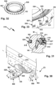
- Multi-axis pivoting with a joint 195 is also possible when a trailer coupling 180 is coupled to a towing vehicle coupling 160.
- the towing vehicle coupling 160 has a ball head 162 as a coupling element 161.
- the ball head 162 is arranged on a free end region of a coupling arm 165, which is attached or releasably attachable to the rear of a towing vehicle Z2, for example a passenger car.
- the coupling arm 165 has, for example, a mounting section 166, in particular a plug-in section for attachment to the towing vehicle Z2.
- Z2 is on the towing vehicle
- a vehicle holder 170 is arranged.
- the vehicle holder 170 comprises a receiving body 171, which is detachably attached in particular to a cross member or other holding structure at the rear of the towing vehicle Z2.
- a plug-in receptacle 172 for inserting the mounting section 166.
- form-fitting contours 167 for example wedge bevels or similar other form-fitting contours, are provided for form-fitting engagement in form-fitting counter-contours 174 on the receiving body 171.
- the coupling arm 165 is given additional support on the vehicle holder 170 by means of a locking device 175.
- the locking device 175 comprises, for example, a locking body 176, in particular balls, bolts or the like, which can be actuated by an actuating body 177, whereby they move into a locking receptacle when actuated accordingly , in particular a groove on the inner circumference of the plug receptacle 172 can be actuated into a locking engagement.
- the actuating body 177 is bolt-like and can be actuated in the longitudinal direction of the mounting section 166, which is indicated by a double arrow.
- a motor drive or, as in the present case, a manual drive 178 can be provided, which can be driven by a hand actuating element 179, in particular a handwheel.
- a pinion engages in a toothing on the actuating body 177 in order to adjust it along its longitudinal direction, whereby the locking bodies 176 are actuated radially outwardly in front of the same through unspecified passage openings on the mounting section 166 in order to move into the Locking receptacle 173 to intervene.
- a fixed attachment of the coupling arm 176 to the towing vehicle Z2 can also be provided or storage using a schematically shown bearing 270, on which the coupling arm 165, for example, between a position of use in which the rear, in particular a bumper, of the Towing vehicle Z2 protrudes, and a non-use position in which it is at least essentially hidden behind and / or under a rear contour of the towing vehicle Z2 is moved back, for example behind a bumper of the towing vehicle Z2.
- the coupling arm 165 can pivot about a pivot axis SA of the bearing 270.
- the trailer coupling 180 is designed as a ball coupling.
- the coupling element 181 is a coupling receptacle 182 into which the ball head 162 and therefore the coupling element 161 can engage in a manner known per se in the sense of a ball joint.
- the ball head 162 is mounted in the coupling receptacle 182, so that the two bodies are in engagement with one another in a storage area 196.
- the coupling counter element 181 can pivot on the coupling element 161 about joint rotation axes GZ, GX and GY, the joint rotation axis GZ being a substantially vertical axis during driving operation, while the other two joint rotation axes GX and GY in the longitudinal direction of the towing vehicle Z2 and run horizontally in the transverse direction.
- these coordinates or orientation of the axes of rotation can also be designed differently.
- the trailer coupling 180 includes, for example, a drawbar or is arranged with a mounting section 183 on a drawbar.
- a locking device 185 is used to lock the trailer coupling 180 on the towing vehicle coupling 160.
- the locking device 185 comprises a locking element 187, for example a clamping jaw or closing jaw, which is adjustable on a pivot bearing 184 between an open position OP and a closed position LO, in the open position the coupling element 161 can be removed from the coupling counter element 181, but not in the closed position LO.
- a manual actuation element 186 for example with a handle, is used to actuate the locking element 187.
- the trailer coupling 180 in connection with the towing vehicle coupling 160 also detects a pivoting movement of the trailer coupling 180 with respect to the towing vehicle coupling 160 about the joint axis of rotation GZ to detect, for which a sensor device 110 is intended.
- the sensor device 110 can be easily mounted subsequently on the towing vehicle coupling 160 without the coupling elements themselves, namely the coupling element 161 and possibly the coupling counter element 181, having to be modified in any way.
- the towing vehicle coupling 160 cannot be changed in the area of a cylinder section 163, in particular a shaft with which the coupling element 161 is held on the coupling arm 165, in particular its upper arm section 164.
- the sensor device 110 is attached to the end region of the coupling arm 165, in particular to the arm section 164 close to the cylinder section 163, so that a driver 120 of the sensor device 110 can come into driving contact with the trailer coupling 180.
- the driver 120 is carried along in rotation on the end face of the dome counter-element 181, in particular an edge region of the coupling receptacle 182, so that it rotates together with the dome counter-element 181 when it is rotated about the joint axis of rotation GZ, for example when a trailer is cornering consisting of towing vehicle Z2 and trailer A2, on which the trailer coupling 180 is arranged.
- the trailer coupling 180 cannot only pivot about the joint axis of rotation GZ, which can be easily detected by the driver 120 and by an arrangement of the driver 120 as in the document, for example EP 2 415 620 A1 described is possible, but also about the joint rotation axes GX and GY.
- a so-called floating or multi-jointed mounting of the driver 120 with respect to the coupling element 161, in particular with regard to the coupling arm 165 is provided.
- the driver 120 has a driving surface 121 which is assigned to and/or faces the end face 188 of the coupling receptacle 182 and which is in particular annular.
- the driver 120 has a driver body 122 on which the driving surface 121 is provided on the front side.
- a side of the driving body 122 or the driver 120 facing away from the driving surface 121 is designed as a bearing section 123, which is rotatably mounted on a bearing body 130 and can also be rotated about rotational degrees of freedom DX and DY.
- the rotational degrees of freedom DX and DY are provided around rotation axes that are parallel to the joint rotation axes GX and GY.
- the driver 120 has a linear displaceability with respect to the bearing body 130, for example around axes parallel to the joint rotation axes GZ, GX and GY.
- a linear degree of freedom of movement LZ can be provided parallel to the driving axis of rotation M.
- the driver 120 is mounted on the bearing body 130 so that it can rotate about the driving rotation axis M and can be pivoted transversely to the driving rotation axis M, namely with the rotational degrees of freedom DX and DY.
- the driver 120 can thus participate in pivoting movements of the trailer coupling 180 about the joint rotation axes GX and GY without the driving contact or the coupling between the driver 120 and the coupling counter element 181 being interrupted.
- the bearing body 130 is annular.
- the bearing body 130 is fastened, for example, to the arm section 164, for example with a screw 141 of a holding device 140.
- the clamping screw 141 runs, for example, radially to the arm section 164 and clamps the bearing body 130 to the coupling arm 165.
- Force application means 150 are provided between the driver 120 and the bearing body 130, for example with a spring arrangement 151.
- the spring arrangement 151 comprises one or more springs 152 which are supported on the bearing body 130 and on the driver body 122 or driver 120.
- the springs 152 are supported on an edge or support section 124 of the driving body 122.
- the support section 124 for example a step, a recess or the like, is arranged between the bearing section 123 and the driving surface 121.
- a further application of force to the driver 120 in the direction of the trailer coupling 180 is provided, for example, by a magnet 153 which is arranged on the driver 120.
- the magnet 153 (several magnets, in particular arranged on the outer circumference of the driver 120, can also be provided) applies a magnetic force to the driver 120 in the direction of the end face 188 or in the direction of the dome counter element 181.
- the coupling process of the trailer coupling 180 to the towing vehicle coupling 160 is in the Figures 12 and 13 clarified. It can be seen that the coupling counter element 181 comes into driving contact with the driver 120 when coupling to the towing vehicle coupling 160, that is, for example, the spring arrangement 151 is compressed when the coupling socket or the coupling receptacle 182 is placed on the ball head 162.
- the dome counter element 181 of the trailer coupling 180 When the dome counter element 181 of the trailer coupling 180 then rotates about the driving axis of rotation M, it takes the driver 120 with it, so that the sensor arrangement 110 uses the sensor or sensors 111 to determine a respective rotational angular position of the driver 120 relative to the bearing body 130 and thus relative to the towing vehicle Z2 or the towing vehicle clutch 160 can detect.
- Sensor sensors 125 are arranged on the driver 120, in particular a ring arrangement with several sensor sensors or magnets 125 arranged around the outer circumference of the coupling arm 165, the respective position of which can be detected by at least one sensor 111 or more, for example two sensors 111a and 111b .
- the sensors 111 therefore detect the magnetic field of the sensor transmitters 125 and thus the angular position of the dome counter element 181 relative to the dome element 161.
- the evaluation device 112 has an interface 115, in particular a radio module or another wireless interface, for communication with the on-board network N.
- interface 115 in particular a radio module or another wireless interface, for communication with the on-board network N.
- Receiver 116 is arranged to receive sensor signals which represent the rotational angular position of the trailer coupling 180 relative to the towing vehicle coupling 160 about the driving axis of rotation M.
- the receiver 116 can, for example, have a bus interface and/or a power supply interface or the like for coupling and/or connection to the on-board network N of the towing vehicle Z2.
- a battery for example, a battery (not shown), a rechargeable battery or the like can be present.
- a power supply using a photocell or another device suitable for generating electrical energy is also easily conceivable.
- a sensor device 210 which has similar components to the sensor device 110 already explained.
- a driver 220 of the sensor device 210 is designed at least as a cover, preferably as a protective housing 229, for the at least one sensor 111 and preferably also the bearing body 130.
- a driving body 222 basically corresponds to the driving body 122, but does not engage into an interior of the bearing body 130, but has a cover section 221 in which the bearing body 130 is at least partially accommodated.
- the driving body 222 can optionally be closed on a side facing away from the driving surface 121 by a cover 223, which is preferably annular and can have a passage opening 225 for the coupling arm 165, in particular its cylinder section 163 and the upper region of the arm section 164.
- a seal in particular a sealing ring, a seal with, for example, silicone or another joint compound, can be provided at the passage opening 225.
- the cover 223 is connected at the front to the driving body 222, for example glued, welded or the like.
- the cover 223 and the driving body 222 overall form a protective housing 229 for the at least one sensor 111 and preferably the bearing body 130.
- a sensor device 310 is intended for arrangement on the towing vehicle coupling 160.
- a holding device 340 for example a retaining ring 342, which is attached to the cylinder section 163 and/or arm section 164 of the towing vehicle coupling 160, for example clamped, glued or the like.
- a corresponding clamping screw is not shown in the drawing for reasons of simplicity.
- the holding device 340 has a bearing holder 341 for a bearing section 331 of a bearing body 330.
- the bearing section 331 and the bearing receptacle 341 are, for example, sections of a ball joint bearing, so they have, for example, ball segments or are designed like ball segments.
- the bearing holder 341 is therefore designed, for example, in the manner of a receiving shell.
- the bearing body 330 can pivot in a ball joint with respect to the retaining ring 342, so that a driver 320 rotatably mounted on the bearing body 330 about the driving axis of rotation M can also participate in movements of the trailer coupling 180 about the joint axes of rotation GX, GY, so to speak, so that its driving surface 321 remains in driving contact with the end face 188 of the trailer coupling 180.
- the driver 320 is mounted on the bearing body 330 using a rolling bearing 333, in particular a ball bearing or roller bearing, so that it can rotate about the driving axis of rotation M.
- the friction of the roller bearing 333 is preferably low, so that the trailer coupling 180 can take and rotate the driver 320 particularly easily.
- the sensor 111 is arranged on the bearing body 330, so that sensor transmitters 25, in particular magnets, on the driver 320, which are in an interior of the bearing body 330 are arranged, rotate about the driving axis of rotation M, but do not pivot transversely to it or change their position in any other way. This means that optimal signal detection can easily be achieved by the sensor 111.
- the sensor transmitters 25 are arranged, for example, on a bearing section 323 of the bearing body 320, on which the rolling bearing 333 is supported.
- a magnet or a magnet arrangement 353 can also be provided as an alternative or in addition to the springs 352, which is arranged on the driver 320 and applies magnetic force to it in the direction of the dome counter element 181.
- the sensor device 110 includes an evaluation device 112, which is arranged, for example, on or in the bearing body 130 ( Figure 10 ).
- the evaluation device 112 comprises, for example, a processor 13 and a memory 14, in which one or more program modules can be stored, the program code of which is provided by the processor 13 for evaluating the sensor signal of the sensor 111 or the sensors 111a, 111b.
- the magnetic measuring principles or sensor principles of the sensor device 10, 110 are not the only embodiment.
- a sensor device according to the invention for example, inductive, capacitive or optical sensors, also in combination, can be provided.
- the sensor transmitters 25, 125 designed as magnets
- optical markings, in particular lines or the like can be provided, which can be detected by an optical sensor 11, 111.
- Capacitive detection is also easily possible if, for example, corresponding electric fields are provided by the sensor transmitters.
- the sensor transmitters 25, 125 other sensor elements or sensors can also be provided. Therefore, the sensory detection of a relative position of a driver relative to a carrier or bearing body can also be realized by at least one sensor, which is arranged on the driver and thus rotates relative to the bearing body or carrier about the driving axis of rotation.
- the drivers 120, 220, 320 can consist entirely or partially of an elastic material, for example a flexible plastic, rubber or the like. Particularly advantageous is elastic flexibility in the area of the driving surface 21.
- the evaluation device 112 already explained can be provided for the respective sensor 111.
- a sensor device 610 like the sensor device 10, is suitable for being taken along by the coupling counter element 81 of the trailer coupling 80 about the driving axis of rotation M.
- the sensor device 610 includes a holding device 640, which can be attached to the support body 72 of the towing vehicle coupling 60 in the manner of the holding device 40.
- the holding device 640 has a holding plate 641, on which a holding part 645 for fastening a bearing body 630 is provided.
- Fastening parts 645A, 645B extend away from the holding part 645 and are designed, for example, in steps.
- the sections 645, 645A and 645B each run in steps towards one another.
- Retaining projections 642 are provided on the fastening parts 645A, 645B, which are suitable, for example, for screwing to the support body 72 of the towing vehicle coupling 60 using, for example, the screws 44.
- the bearing body 630 serves to support the driver 620 about the driving axis of rotation M.
- an upper pivot bearing 33 is arranged on an end region of the bearing body 630 facing away from the holding plate 641, in particular on a flange projection 31.
- a further bearing 34 is provided at a distance from the bearing 33 with respect to the driving axis of rotation M.
- the bearings 33, 34 form a bearing arrangement 32, which supports the driver 20 so that it can rotate about the driving axis of rotation M with respect to the bearing body 630.
- the pivot bearing 34 is arranged on a support body 39, which in turn is supported on the bearing body 630.
- the driver 620 is similar to the driver 20 in that it has a peripheral wall 622 and an end wall 621A and is, for example, essentially cylindrical or conical, in particular mushroom-shaped.
- the end wall 621A is intended for rotational driving by the dome counter element 81.
- the driver 620 forms a protective housing 29 with a protected interior 29A, in which the electronic components of the sensor device 610 are arranged, in particular the sensor 11 already explained. This is located in the interior of the sensor carrier 24, on which at least one sensor transmitter 25, e.g. a magnet , is arranged to actuate the sensor 11.
- the bearing body 630 has a channel 637 which communicates with a passage opening 646 of the holding plate 641, so that a line arrangement VX can be guided through these two components to the evaluation device 12 and the sensor 11.
- a magnet 653 in the manner of magnet 53 is arranged on the end wall 621A.
- the magnet 653 is arranged in a shield 654, which has, for example, a bottom wall 654A and a peripheral wall 654B.
- the bottom wall 654A is penetrated at right angles by the driving axis of rotation M, while the peripheral wall 654B extends around the driving axis of rotation M.
- the magnet 653 is therefore shielded from the sensor 11 and cannot influence it.
- bearing bodies 644 which penetrate the through openings 643 of the holding device 640 on the holding projections 642 and are connected to the towing vehicle coupling 60, in particular the support body 72, with fastening sections 644C, for example screwed, glued or welded.
- fastening sections 644C for example screwed, glued or welded.
- screw threads can be provided on the fastening sections 644C.
- the bearing bodies 644 are advantageously designed like a bolt.
- the bearing bodies 644 form components of bearing devices 655, which mount the holding device 640 both pivotally and displaceably with respect to the support body 72.
- the bearing devices 655 each include a pivot bearing 656, in particular a multi-axis pivot bearing, namely a ball bearing, and a sliding bearing 657.
- bearing bodies 658 are accommodated in the passage openings 643, which can also be referred to as bearing receptacles.
- Bearing receptacles 656A of the pivot bearing 656 are provided on the bearing bodies 658.
- a bearing body 659 in the form of a ball or partial ball is accommodated in the bearing receptacles 656A.
- the bearing body 656 can pivot in the bearing receptacle 656A in multiple axes, for example about the axes SX and/or SY or axes parallel to them.
- a bearing receptacle 657A namely a sliding bearing receptacle, is provided in the bearing body 659 for the bearing body 644.
- the bearing body 644 is therefore longitudinally displaceable in the bearing receptacle 657A along a displacement axis ZZ, which is indicated by a double arrow PZ.
- the pivotability of the bearing body 644 with respect to the bearing receptacles 655A or the pivotability of the bearing body 658 around the bearing body 659, so that the holding device 640 can pivot with respect to the bearing body 644, is indicated by dashed lines.
- the holding device 640 in particular the holding plate 641, can be axially displaced both about the axial direction PZ with respect to the respective bearing body 644, as well as about mutually angled pivot axes which are at the intersection of the central longitudinal axis of the bearing body 644 with the central plane of the holding plate 641 in the area of respective holding projection 642 lie, can be pivoted.
- the drawing shows how the holding plate 641 can be deflected due to the mobility on the pivot bearings 656 and sliding bearings 657.
- the deflection is exaggerated in the drawing. In practice, a slight deflection of, for example, a few degrees is sufficient to enable or facilitate the dome counter element 81 to deflect the driver 620 from its central position so that it can slide onto the end wall 621A.
- the bearing bodies 658 are accommodated in the passage openings 643 with a movement transverse to the displacement axis ZZ or longitudinal axis of the sliding bearings 657.
- a bearing area 643A of the holding plate 641 protrudes in the area of the respective passage opening 643 into a bearing receptacle 658A, for example a bearing groove, on the bearing body 658.
- the storage area 643A can be circular, for example, but can also include other contours, for example an elongated hole.
- an oval or elongated storage area 643B can also be provided, which is indicated schematically.
- the bearing receptacle 658A can be, for example, a circumferential groove on the bearing body 658.
- the bearing body 658 is thus movably received in the passage opening 643 transversely to the direction of movement, which is indicated by the double arrow PZ. This can advantageously avoid tension.
- bearing body 658 it would also be possible, for example, to connect the bearing body 658 to the holding plate 641 using an elastomer, so that the bearing body 658 is accommodated in the holding plate 641 in a floating manner, so to speak.
- the holding plate 641 is also subjected to force with respect to the bearing body 644, namely by a force applying means 650.
- the force applying means 650 comprises a spring arrangement 651 with springs 652.
- the springs 652 are each supported on a head 644A of a bearing body 644 on the one hand and on the other hand on a head 644A with respect to the holding plate 641 or the holding device 640 stationary or non-displaceable component, for example one of the bearing bodies 658 or 659.
- the springs 652 are penetrated by a bearing section 644B of a respective bearing body 644.
- the bearing section 644B is accommodated in the bearing holder 657A so that it can be moved longitudinally.
- the driver 620 is constructed in several parts. It has a driver carrier 667, the basic contour of which is similar to the driver 20, namely an end wall 668 and the peripheral wall 622.
- the driver carrier forms the protective housing for, among other things, the sensor 11 and the evaluation device 12 and is rotatably mounted on the bearing body 630 using the bearing arrangement 32.
- a driving body 660 is detachably attached to the driver carrier 667, for example glued, screwed or the like.
- the driver body 660 forms, so to speak, the wearing part that can be easily replaced, while the driver carrier 667 remains permanently on the bearing body 630.
- an underside 666 of the driving body 660 is glued to the end wall 668 and/or lies flat against it.
- a screw arrangement with screws 665 can be provided, which penetrate a base body 661 of the driver body 660 at passage openings 664 and are screwed into screw receptacles 669 of the driver carrier 667.
- the driving body 660 has a receptacle 663 for the magnet 653 centrally with respect to the driving axis of rotation M.
- the shield 654 is included in the receptacle 663.
- Several recesses 662 extend on the radial outer circumference of the receptacle 663, which serve, for example, to make the driving body 660 easier to compress at its edge region, which can make it easier for the dome counter element 81 to slide onto the driver 620.
- the edge region of the driving body 660 extending around the recesses 662 is inclined flat and has the slope 622A.
- the recesses 662 can also serve to ensure that the driving body 660 is particularly light or that little material is required for it.
- the recesses 662 can also serve to ensure that the driving body 660 can be produced in a dimensionally stable manner.
- the magnet 663 and/or the shield 654 can be glued, inserted or screwed into the material of the driving body 660. However, it is also possible to encapsulate the magnet 653 and/or the shield 654 with the material of the driving body 660.
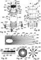
- the end wall 621A or end face of the driver 620 is designed as a friction surface 681 and serves for the frictional driving contact of the driver 620 with the dome counter element 81. It would now be possible to have the friction surface 681 directly on a free end face or flat side 653A of the drive that projects in front of the receptacle 663 Magnets 653 are to be provided, for example by firmly connecting the particles 683 explained below to this free end face 653A by means of gluing or other lamination.
- the friction body 680 is, for example, plate-like or film-like and is firmly arranged, for example glued, on the free end face 653A of the magnet 653.
- the friction body 680 can also be formed by a material of the driving body 660, which encloses the magnet 653 and in which the particles 683 are directly embedded.
- the friction body 680 has the friction surface 681 on its side facing away from the magnet 653.
- the particles 683 protrude in front of a supporting surface 682 of the friction body 680.
- the friction body 680 is glued to the end face 653A of the magnet 653 using an adhesive layer 686.
- the friction body 680 has a base body or a base layer 685, which has the adhesive layer 686 on the one hand and a support layer 684 for the particles 683 on the other hand on opposite sides.
- the support layer 684 which is also referred to as a binding layer or adhesive layer can carry the particles 683. These are, so to speak, embedded in the base layer 684 and protrude freely in front of it.
- the particles 683 protrude in front of the supporting surface 682, for example, in the manner of pyramids.
- their tips 687 for example pyramid tips
- the side surfaces of the particles 683 run from the tips 687 towards the supporting surface 682, with edges 688 being formed between the respective side surfaces.
- a central surface 690 of the friction surface 681 is without particles 683.
- the supporting surface 682 is free there.
- the central surface 690 is penetrated by the driving axis of rotation M.
- the particles 683 run from the central surface 690 or the driving axis of rotation M along rays 689 and are therefore arranged regularly.
- the tips 687 or the free end regions of the particles 683 protrude approximately the same distance from the supporting surface 682. Thus, the tips 687 do not “pierce” an envelope 691.
- the envelope 691 is a flat surface or flat surface, corresponding to the flat or flat surface of the end face 88 of the dome counter element 81.
- the radial arrangement of the particles 683 on the supporting surface 682 alone results in a higher concentration of particles 683 close to the central surface 690 than at the radially outer edge region of the friction body 680 or the friction surface 681.
- the particles 683 are arranged in a ring or annular shape around the driving axis of rotation M.
- a chaotic arrangement or an arrangement with different distributions or fields would also be possible.
- the angular distance between the particles 683 can also be smaller at the radial outer circumference than near the central surface 690, unlike shown in the drawing.
- the particles 683 are preferably corundum, quartz, rock particles or similar other hard material with sharp breaking edges and in any case points.
- the base layer 684 contains, for example, glue and/or epoxy resin in order to glue or bind the particles 683 to the base layer 685.
- the support layer 684 and/or the base layer 685 and/or the adhesive layer 686 may be elastic components and/or consist of an elastic material or contain an elastic material.
- a cover layer 692 can also be provided, for example made of a wax or the like.
- the edges 688 at least partially, but in any case the pyramid tips or tips 687, of the particles 683 protrude in front of the cover layer 692.
- the cover layer 692 expediently consists of a softer material than the particles 683 so that they can make contact with the dome counter element 81.
- the distribution and/or arrangement of particles on a friction surface can also be designed differently than in the aforementioned exemplary embodiment, which should become clearer using friction bodies 780, 880.
- the particles 683 of the friction surfaces 781, 881 of the friction bodies 780, 880 could also be provided directly on the driving body 660 or the magnet 653.
- the particles 683 are arranged in the friction body 780, for example in rings 793, 794, 795, which run concentrically around a center of the circular friction body 780.
- the supporting surface lies between the rings 793-795 782 free, in which the particles 683 are embedded in the rings 793, 794, 795.
- the center 790 or the central surface 790 of the friction body 780 is also without particles 683, so that the supporting surface 782 is exposed there for direct frictional entrainment of the dome counter element 81.
- the particles 683 are arranged in angular segments 893, which, for example, extend in a radial manner around the driving axis of rotation M. Between the angle segments 893, where the particles 83 of the friction surface 881 of the friction body 880 are located, angle segments of the supporting surface 882 are also exposed, i.e. without particles.
- the principle of improved frictional engagement based on the particles can also be easily implemented with a dome counter-element, which works together with a driver that has particles for frictional contact with the dome counter-element, or also works together with such a driver on which no such particles are provided are.
- particles 683 can be provided on the dome counter element 81. These particles can be provided, for example, by one of the friction bodies 680, 780 or 880, which is attached, for example, to the end face 88 or driving surface 90 and forms a counter-drive element 990.
- the friction body 680, 780 or 880 can, for example, be materially connected to the end face 88 or driving surface 90 and/or glued to it. However, it is also possible for the friction body 680, 780 or 880 to be positively connected to the end face 88 or driving surface 90, for example screwed, riveted, mortised or the like.
- the end face 90 may have integral particles 683, for example in that particles 683 are or are scattered into the hot base material of the end face 88 of the dome counter element 81 and/or in which a layer, in particular an adhesive layer, on the end face 88 is arranged, for example a layer of rubber, elastic plastic or the like, which particles 683 are embedded.
- a sensor device 410 has, so to speak, a central storage for a driver 420, which is essentially the same as the driver 620.
- the driver 420 therefore also has a driving body 460 which is provided for the actual frictional connection or driving contact with the dome counter element 81 and which is similar to the driving body 660, as well as a driving carrier 467 which carries the driving body 460 in accordance with the driving carrier 667.
- the driving carrier 467 is mounted on the bearing body 430 by means of the pivot bearings 33, 34, which have a longitudinal distance with respect to the driving axis of rotation M, which also has a support body 39 to support the pivot bearing 34 at the bottom in the drawing, which is from Bearing body 430 is penetrated.
- a flange projection or the like can of course also be provided, which projects radially in front of the bearing body 430.
- the protective housing which is formed by the driver carrier 667, is covered by a bottom wall 23, which is penetrated by the bearing body 430.
- the bearing body 430 is supported on a holding device 440, which is connected to the support body 72, namely by means of screws 444 which are screwed into the support body 72 and whose heads 444A are supported on a holding plate 441 of the holding device 440.
- the holding plate 441 is stationary with respect to the towing vehicle coupling 60, in particular its support body 72.
- the mobility of the driver 420 is ensured by a bearing device 455, with which the bearing body 430 is movably mounted on the holding device 440, in particular the holding plate 441, namely in a sliding manner with a linear degree of freedom of movement LZ parallel to the driving axis of rotation M, as well as transversely to the driving axis.
- Rotation axis M by one or more degrees of freedom of rotation, namely around axes SY and SX.
- the bearing device 455 has a multi-joint pivot bearing 456 designed as a ball bearing.
- a bearing body 459 which is on its outer circumference is spherical or is spherical segment-shaped, pivotally mounted in a bearing body 458, which is stationary with respect to the holding device 440, for example on the holding plate 441, namely in a bearing holder 456A.
- the bearing body 459 in turn has a sliding bearing receptacle 457A, which is provided in a sliding bearing 457.
- the bearing receptacle 457A is penetrated by a bearing section 433 of the bearing body 430, which protrudes in front of the driver 420.
- the bearing section 433 can therefore be linearly displaced in the bearing holder 457A with respect to the axis GZ or the driving axis of rotation M and can pivot transversely to this axis using the pivot bearing 456 in one or more axes.
- the linear displacement is shown in dashed lines in the cross-sectional view.
- the pivoting mobility is also indicated in the side view with dashed lines, but is particularly exaggerated in the drawing.
- the friction surface 681 can of course also be designed differently, so that, for example, one of the friction bodies 780 or 880 is arranged there.
- the friction bodies 680, 780 or 880 can also be easily arranged on the end wall 21A, for example glued or the like.
- the particles 683 can also be embedded directly in the end wall 21A.
- the driver 20 consists of a plastic material, in particular an elastic plastic material, in particular a rubber material, into which particles, in particular corundum, glass splinters or similar other sharp-edged particles can easily be scattered during the manufacturing process.
- the principle with particles on friction surfaces can easily be implemented with the sensor devices 110, 210 or 310 if, for example, the driving surfaces 121, 321 are provided with particles 683.
- a friction body 980 is arranged, on which particles 683 are present.
- the friction body 980 forms a counter-drive element 990.
- the structure of the friction body 980 is similar to that of the friction body 680, 780 or 880, i.e. H. that, for example, on the one hand the adhesive layer 686 and on the other hand a support layer 684 for the particles 683 are provided on opposite sides.
- the particles 683 protrude, for example, in the manner of pyramids, in front of a supporting surface 982 of the friction body 980, on the back of which the adhesive layer 686 is provided.
- a sensor device 510 for a towing vehicle coupling 560 is arranged, for example, directly on its coupling element 561, for example a coupling ball 562.
- the driver 520 is annular and extends near the equator of the ball 562, but not on the equator of the ball.
- the annular driver 620 can rotate about a driving axis of rotation M, about which it is rotatably mounted on the coupling element 561.
- the driver 520 is rotatably mounted in a bearing holder 518, which extends over its entire outer circumference on the radial outer circumference, close to the spherical surface of the ball 562.
- a bearing holder 518 which extends over its entire outer circumference on the radial outer circumference, close to the spherical surface of the ball 562.
- a partially ring-shaped configuration of a driver of the type described below would also be possible.
- the coupling element 561 has a sensor receptacle 517, in which an evaluation device 512 and a sensor 511 for detecting signals from sensor transmitters 25, for example magnets, are arranged.
- the driver 520 has a driver body 527 which is attached to a driver carrier 524 is.
- the driver carrier 524 has one or more sensor transmitters 25, which are arranged in a ring and extend around the driver rotation axis M. So when the driver carrier 524 rotates about the driver rotation axis M, the magnets or other sensor transmitters rotate past the sensor 511 so that it can detect a respective rotation angle position.
- the evaluation device 512 in the sensor receptacle 527 is embedded, for example, in a holding mass 519 or a similar other holding body.
- This body also has a section of the bearing groove or bearing receptacle 518.
- the driver 520 in particular its driving body 660, has a plurality of driving projections 521 on its radial outer circumference 522, between which distances or spaces 523 are arranged.
- the driving projections 521 can be displaced into the distances 523 if a pressure coming radially from the outside, namely through, for example, the trailer coupling 180 or its coupling counter element 181, acts on a driving projection 521.
- particles 683 for example rock particles, corundum, diamond or the like, are arranged on the driving projections 521, the tips of which protrude radially outwards in front of the respective driving projection 521 and can accordingly establish a frictional contact on the coupling counter element 181 when the trailer coupling 180 is on the towing vehicle coupling 560 is coupled.
- the coupling element 561 is arranged on a coupling arm 565 and can be adjusted between a use position GS and a non-use position NG using a bearing 570, for example pivoted in one or more axes and/or linearly displaced or the like.
- a bearing 570 for example pivoted in one or more axes and/or linearly displaced or the like.
- a drive motor suitable for this is not shown for reasons of simplicity.
- the coupling arm 565 is hidden behind a rear contour, for example a rear apron, of a towing vehicle Z3, on which the towing vehicle coupling 560 is arranged.
Landscapes
- Engineering & Computer Science (AREA)
- Transportation (AREA)
- Mechanical Engineering (AREA)
- Chemical & Material Sciences (AREA)
- Combustion & Propulsion (AREA)
- Transmission And Conversion Of Sensor Element Output (AREA)
- Force Measurement Appropriate To Specific Purposes (AREA)
- Measurement Of Length, Angles, Or The Like Using Electric Or Magnetic Means (AREA)
Applications Claiming Priority (3)
| Application Number | Priority Date | Filing Date | Title |
|---|---|---|---|
| DE102018116192.1A DE102018116192A1 (de) | 2018-07-04 | 2018-07-04 | Zugfahrzeugkupplung-Sensorvorrichtung mit reibschlüssigem Mitnehmer |
| EP19736365.8A EP3817931B1 (fr) | 2018-07-04 | 2019-07-03 | Dispositif de détection d'attelage de véhicule tracteur ayant un entraîneur à friction |
| PCT/EP2019/067826 WO2020007903A1 (fr) | 2018-07-04 | 2019-07-03 | Dispositif de détection d'attelage de véhicule tracteur ayant un entraîneur à friction |
Related Parent Applications (3)
| Application Number | Title | Priority Date | Filing Date |
|---|---|---|---|
| EP19736365.8A Division-Into EP3817931B1 (fr) | 2018-07-04 | 2019-07-03 | Dispositif de détection d'attelage de véhicule tracteur ayant un entraîneur à friction |
| EP19736365.8A Division EP3817931B1 (fr) | 2018-07-04 | 2019-07-03 | Dispositif de détection d'attelage de véhicule tracteur ayant un entraîneur à friction |
| PCT/EP2019/067826 Previously-Filed-Application WO2020007903A1 (fr) | 2018-07-04 | 2019-07-03 | Dispositif de détection d'attelage de véhicule tracteur ayant un entraîneur à friction |
Publications (2)
| Publication Number | Publication Date |
|---|---|
| EP4245578A2 true EP4245578A2 (fr) | 2023-09-20 |
| EP4245578A3 EP4245578A3 (fr) | 2023-11-08 |
Family
ID=67180782
Family Applications (2)
| Application Number | Title | Priority Date | Filing Date |
|---|---|---|---|
| EP19736365.8A Active EP3817931B1 (fr) | 2018-07-04 | 2019-07-03 | Dispositif de détection d'attelage de véhicule tracteur ayant un entraîneur à friction |
| EP23181347.8A Withdrawn EP4245578A3 (fr) | 2018-07-04 | 2019-07-03 | Dispositif de détection d'attelage de véhicule tracteur ayant un entraîneur à friction |
Family Applications Before (1)
| Application Number | Title | Priority Date | Filing Date |
|---|---|---|---|
| EP19736365.8A Active EP3817931B1 (fr) | 2018-07-04 | 2019-07-03 | Dispositif de détection d'attelage de véhicule tracteur ayant un entraîneur à friction |
Country Status (5)
| Country | Link |
|---|---|
| US (1) | US11530004B2 (fr) |
| EP (2) | EP3817931B1 (fr) |
| DE (1) | DE102018116192A1 (fr) |
| MX (1) | MX393835B (fr) |
| WO (1) | WO2020007903A1 (fr) |
Cited By (1)
| Publication number | Priority date | Publication date | Assignee | Title |
|---|---|---|---|---|
| DE102023206424B3 (de) | 2023-07-06 | 2024-10-17 | Audi Aktiengesellschaft | Bauteilanordnung für ein Kraftfahrzeug sowie Verfahren zum Montieren einer Bauteilanordnung |
Families Citing this family (6)
| Publication number | Priority date | Publication date | Assignee | Title |
|---|---|---|---|---|
| EP4201715A1 (fr) * | 2017-11-23 | 2023-06-28 | WESTFALIA - Automotive GmbH | Dispositif de détection pour un attelage de véhicule tracteur |
| WO2022122657A1 (fr) * | 2020-12-09 | 2022-06-16 | Westfalia-Automotive Gmbh | Appareil de détection doté d'un dispositif de réglage |
| CN114649696A (zh) * | 2020-12-18 | 2022-06-21 | 威卡亚力山大维甘德欧洲两合公司 | 电组件 |
| US11608127B1 (en) * | 2022-04-28 | 2023-03-21 | Mod.Al Group, Inc. | Trailer electrical connector assembly |
| DE102022111393A1 (de) | 2022-05-06 | 2023-11-09 | Jost-Werke Deutschland Gmbh | Sattelkupplungssystem, Zugfahrzeug und Sattelzug |
| CN222420916U (zh) * | 2024-05-24 | 2025-01-28 | 邵东市通驰科技发展有限公司 | 一种键盘的快拆结构 |
Citations (1)
| Publication number | Priority date | Publication date | Assignee | Title |
|---|---|---|---|---|
| EP2415620A1 (fr) | 2010-08-06 | 2012-02-08 | WESTFALIA - Automotive GmbH | Attelage doté d'un capteur |
Family Cites Families (7)
| Publication number | Priority date | Publication date | Assignee | Title |
|---|---|---|---|---|
| EP0486693A4 (en) * | 1990-03-19 | 1992-10-07 | Zaporozh Avtomobil | Friction element for friction pair |
| AT504820B1 (de) * | 2007-02-09 | 2012-10-15 | Miba Frictec Gmbh | Reibbelag |
| DE102009057871A1 (de) * | 2009-12-11 | 2011-06-16 | Westfalia-Automotive Gmbh | Anhängekupplung mit einer Sensoranordnung und einem Drehmitnahmekörper |
| DE102015120327A1 (de) * | 2015-11-24 | 2017-05-24 | Scambia Holdings Cyprus Limited | Anhängekupplung |
| DE102016012663A1 (de) | 2016-10-22 | 2017-06-01 | Daimler Ag | Kopplungseinrichtung für einen Lastzug mit anhängerunabhängiger Knickwinkelsensierung |
| EP4201715A1 (fr) * | 2017-11-23 | 2023-06-28 | WESTFALIA - Automotive GmbH | Dispositif de détection pour un attelage de véhicule tracteur |
| US11512979B2 (en) * | 2017-11-23 | 2022-11-29 | Westfalia-Automotive Gmbh | Sensor device for a towing vehicle coupling |
-
2018
- 2018-07-04 DE DE102018116192.1A patent/DE102018116192A1/de not_active Withdrawn
-
2019
- 2019-07-03 MX MX2020014236A patent/MX393835B/es unknown
- 2019-07-03 WO PCT/EP2019/067826 patent/WO2020007903A1/fr not_active Ceased
- 2019-07-03 EP EP19736365.8A patent/EP3817931B1/fr active Active
- 2019-07-03 EP EP23181347.8A patent/EP4245578A3/fr not_active Withdrawn
- 2019-07-03 US US17/257,649 patent/US11530004B2/en active Active
Patent Citations (1)
| Publication number | Priority date | Publication date | Assignee | Title |
|---|---|---|---|---|
| EP2415620A1 (fr) | 2010-08-06 | 2012-02-08 | WESTFALIA - Automotive GmbH | Attelage doté d'un capteur |
Cited By (1)
| Publication number | Priority date | Publication date | Assignee | Title |
|---|---|---|---|---|
| DE102023206424B3 (de) | 2023-07-06 | 2024-10-17 | Audi Aktiengesellschaft | Bauteilanordnung für ein Kraftfahrzeug sowie Verfahren zum Montieren einer Bauteilanordnung |
Also Published As
| Publication number | Publication date |
|---|---|
| EP3817931A1 (fr) | 2021-05-12 |
| EP3817931B1 (fr) | 2023-08-02 |
| US20210206217A1 (en) | 2021-07-08 |
| WO2020007903A1 (fr) | 2020-01-09 |
| DE102018116192A1 (de) | 2020-01-09 |
| MX393835B (es) | 2025-03-11 |
| MX2020014236A (es) | 2022-07-11 |
| EP4245578A3 (fr) | 2023-11-08 |
| US11530004B2 (en) | 2022-12-20 |
Similar Documents
| Publication | Publication Date | Title |
|---|---|---|
| EP3817931B1 (fr) | Dispositif de détection d'attelage de véhicule tracteur ayant un entraîneur à friction | |
| EP3713782B1 (fr) | Dispositif de détection pour un système d'attelage de véhicule tracteur | |
| EP3713781B1 (fr) | Dispositif de détection pour système d'attelage de véhicule tracteur | |
| EP2905155B1 (fr) | Attelage doté d'un capteur | |
| EP2826645B1 (fr) | Attelage doté d'un système de capteur et d'un corps d'entraînement rotatif | |
| DE60304489T2 (de) | Spannmutter für eine osteosynthesevorrichtung | |
| EP3856542B1 (fr) | Dispositif de détection avec un actionneur | |
| AT512049B1 (de) | Bearbeitungsvorrichtung für ein zahntechnisches werkstück | |
| EP2511110B1 (fr) | Attelage doté d'un capteur | |
| DE102010010242A1 (de) | Anhängekupplung mit einer Sensoranordnung und einem Drehmitnahmekörper | |
| EP2099683A1 (fr) | Plateau d'appui | |
| EP3079827B1 (fr) | Dispositif de broyage avec plaquette d`usure | |
| DE102018123644A1 (de) | Sensorvorrichtung mit einer Schwenklageranordnung | |
| DE202009017810U1 (de) | Anhängekupplung mit einer Sensoranordnung und einem Drehmitnahmekörper | |
| DE102014107967A1 (de) | Anhängekupplung | |
| DE102017127744A1 (de) | Sensorvorrichtung für eine Zugfahrzeugkupplung | |
| EP1369266B1 (fr) | Dispositif d'accouplement | |
| DE102017127743A1 (de) | Sensorvorrichtung für eine Zugfahrzeugkupplung | |
| DE102006047442B3 (de) | Gleitschleifkörper | |
| DE102017114839A1 (de) | Gewürzmühle | |
| DE202013105675U1 (de) | Vorrichtung zur Flächenbearbeitung von Böden und Belägen | |
| DE8100044U1 (de) | "kombiniertes fraes- und schleifwerkzeug" | |
| CH697639B1 (de) | Ökologische Mühle. | |
| DE1502508A1 (de) | Schleifkoerperhalterung | |
| DE202015101908U1 (de) | Anordnung für ein Fahrzeugdach |
Legal Events
| Date | Code | Title | Description |
|---|---|---|---|
| PUAI | Public reference made under article 153(3) epc to a published international application that has entered the european phase |
Free format text: ORIGINAL CODE: 0009012 |
|
| STAA | Information on the status of an ep patent application or granted ep patent |
Free format text: STATUS: THE APPLICATION HAS BEEN PUBLISHED |
|
| AC | Divisional application: reference to earlier application |
Ref document number: 3817931 Country of ref document: EP Kind code of ref document: P |
|
| AK | Designated contracting states |
Kind code of ref document: A2 Designated state(s): AL AT BE BG CH CY CZ DE DK EE ES FI FR GB GR HR HU IE IS IT LI LT LU LV MC MK MT NL NO PL PT RO RS SE SI SK SM TR |
|
| REG | Reference to a national code |
Ref country code: DE Ref legal event code: R079 Free format text: PREVIOUS MAIN CLASS: B60D0001060000 Ipc: B60D0001010000 |
|
| PUAL | Search report despatched |
Free format text: ORIGINAL CODE: 0009013 |
|
| AK | Designated contracting states |
Kind code of ref document: A3 Designated state(s): AL AT BE BG CH CY CZ DE DK EE ES FI FR GB GR HR HU IE IS IT LI LT LU LV MC MK MT NL NO PL PT RO RS SE SI SK SM TR |
|
| RIC1 | Information provided on ipc code assigned before grant |
Ipc: B60D 1/06 20060101ALI20231005BHEP Ipc: B60D 1/62 20060101ALI20231005BHEP Ipc: B60D 1/01 20060101AFI20231005BHEP |
|
| STAA | Information on the status of an ep patent application or granted ep patent |
Free format text: STATUS: THE APPLICATION IS DEEMED TO BE WITHDRAWN |
|
| 18D | Application deemed to be withdrawn |
Effective date: 20240509 |