EP4245887A1 - Vorrichtung zum abscheiden eines produktgases aus einem elektrolysemedium - Google Patents
Vorrichtung zum abscheiden eines produktgases aus einem elektrolysemedium Download PDFInfo
- Publication number
- EP4245887A1 EP4245887A1 EP22162399.4A EP22162399A EP4245887A1 EP 4245887 A1 EP4245887 A1 EP 4245887A1 EP 22162399 A EP22162399 A EP 22162399A EP 4245887 A1 EP4245887 A1 EP 4245887A1
- Authority
- EP
- European Patent Office
- Prior art keywords
- electrolysis
- gas
- vessel
- product gas
- phase part
- Prior art date
- Legal status (The legal status is an assumption and is not a legal conclusion. Google has not performed a legal analysis and makes no representation as to the accuracy of the status listed.)
- Pending
Links
- 238000005868 electrolysis reaction Methods 0.000 title claims abstract description 201
- 239000007788 liquid Substances 0.000 claims abstract description 81
- 238000001816 cooling Methods 0.000 claims abstract description 79
- 239000012071 phase Substances 0.000 claims abstract description 43
- 238000012546 transfer Methods 0.000 claims abstract description 42
- 239000007791 liquid phase Substances 0.000 claims abstract description 41
- 238000007599 discharging Methods 0.000 claims abstract description 23
- 238000009833 condensation Methods 0.000 claims abstract description 6
- 230000005494 condensation Effects 0.000 claims abstract description 6
- 230000000694 effects Effects 0.000 claims abstract description 6
- 238000001035 drying Methods 0.000 claims abstract description 5
- 239000007789 gas Substances 0.000 claims description 166
- 239000002826 coolant Substances 0.000 claims description 34
- XLYOFNOQVPJJNP-UHFFFAOYSA-N water Substances O XLYOFNOQVPJJNP-UHFFFAOYSA-N 0.000 claims description 29
- 239000001257 hydrogen Substances 0.000 claims description 18
- 229910052739 hydrogen Inorganic materials 0.000 claims description 18
- UFHFLCQGNIYNRP-UHFFFAOYSA-N Hydrogen Chemical compound [H][H] UFHFLCQGNIYNRP-UHFFFAOYSA-N 0.000 claims description 16
- 230000005484 gravity Effects 0.000 claims description 8
- 238000011144 upstream manufacturing Methods 0.000 claims description 5
- 238000010438 heat treatment Methods 0.000 claims description 4
- 239000012530 fluid Substances 0.000 claims description 2
- 238000004519 manufacturing process Methods 0.000 claims description 2
- 239000000047 product Substances 0.000 description 81
- QVGXLLKOCUKJST-UHFFFAOYSA-N atomic oxygen Chemical compound [O] QVGXLLKOCUKJST-UHFFFAOYSA-N 0.000 description 16
- 239000001301 oxygen Substances 0.000 description 16
- 229910052760 oxygen Inorganic materials 0.000 description 16
- KWYUFKZDYYNOTN-UHFFFAOYSA-M Potassium hydroxide Chemical compound [OH-].[K+] KWYUFKZDYYNOTN-UHFFFAOYSA-M 0.000 description 5
- 239000003792 electrolyte Substances 0.000 description 5
- 238000003487 electrochemical reaction Methods 0.000 description 4
- 150000002431 hydrogen Chemical class 0.000 description 3
- 238000000034 method Methods 0.000 description 3
- 239000006227 byproduct Substances 0.000 description 2
- 238000006243 chemical reaction Methods 0.000 description 2
- 238000007872 degassing Methods 0.000 description 2
- 239000008367 deionised water Substances 0.000 description 2
- 239000012535 impurity Substances 0.000 description 2
- 239000011261 inert gas Substances 0.000 description 2
- 238000005259 measurement Methods 0.000 description 2
- 238000005070 sampling Methods 0.000 description 2
- 241000446313 Lamella Species 0.000 description 1
- 230000002745 absorbent Effects 0.000 description 1
- 239000002250 absorbent Substances 0.000 description 1
- 239000006096 absorbing agent Substances 0.000 description 1
- 238000010521 absorption reaction Methods 0.000 description 1
- 230000003197 catalytic effect Effects 0.000 description 1
- 229910021641 deionized water Inorganic materials 0.000 description 1
- 230000001419 dependent effect Effects 0.000 description 1
- 238000013461 design Methods 0.000 description 1
- 238000010586 diagram Methods 0.000 description 1
- 238000005755 formation reaction Methods 0.000 description 1
- 239000004615 ingredient Substances 0.000 description 1
- 239000012528 membrane Substances 0.000 description 1
- 229910052751 metal Inorganic materials 0.000 description 1
- 239000002184 metal Substances 0.000 description 1
- 239000000203 mixture Substances 0.000 description 1
- 239000002808 molecular sieve Substances 0.000 description 1
- 230000000704 physical effect Effects 0.000 description 1
- 238000012545 processing Methods 0.000 description 1
- 239000000376 reactant Substances 0.000 description 1
- 238000000926 separation method Methods 0.000 description 1
- URGAHOPLAPQHLN-UHFFFAOYSA-N sodium aluminosilicate Chemical compound [Na+].[Al+3].[O-][Si]([O-])=O.[O-][Si]([O-])=O URGAHOPLAPQHLN-UHFFFAOYSA-N 0.000 description 1
- 239000007787 solid Substances 0.000 description 1
- 239000008400 supply water Substances 0.000 description 1
Images



Classifications
-
- C—CHEMISTRY; METALLURGY
- C25—ELECTROLYTIC OR ELECTROPHORETIC PROCESSES; APPARATUS THEREFOR
- C25B—ELECTROLYTIC OR ELECTROPHORETIC PROCESSES FOR THE PRODUCTION OF COMPOUNDS OR NON-METALS; APPARATUS THEREFOR
- C25B15/00—Operating or servicing cells
- C25B15/08—Supplying or removing reactants or electrolytes; Regeneration of electrolytes
- C25B15/083—Separating products
-
- B—PERFORMING OPERATIONS; TRANSPORTING
- B01—PHYSICAL OR CHEMICAL PROCESSES OR APPARATUS IN GENERAL
- B01D—SEPARATION
- B01D19/00—Degasification of liquids
- B01D19/0036—Flash degasification
-
- B—PERFORMING OPERATIONS; TRANSPORTING
- B01—PHYSICAL OR CHEMICAL PROCESSES OR APPARATUS IN GENERAL
- B01D—SEPARATION
- B01D53/00—Separation of gases or vapours; Recovering vapours of volatile solvents from gases; Chemical or biological purification of waste gases, e.g. engine exhaust gases, smoke, fumes, flue gases, aerosols
- B01D53/34—Chemical or biological purification of waste gases
- B01D53/74—General processes for purification of waste gases; Apparatus or devices specially adapted therefor
- B01D53/75—Multi-step processes
-
- B—PERFORMING OPERATIONS; TRANSPORTING
- B01—PHYSICAL OR CHEMICAL PROCESSES OR APPARATUS IN GENERAL
- B01D—SEPARATION
- B01D53/00—Separation of gases or vapours; Recovering vapours of volatile solvents from gases; Chemical or biological purification of waste gases, e.g. engine exhaust gases, smoke, fumes, flue gases, aerosols
- B01D53/34—Chemical or biological purification of waste gases
- B01D53/74—General processes for purification of waste gases; Apparatus or devices specially adapted therefor
- B01D53/86—Catalytic processes
- B01D53/8671—Removing components of defined structure not provided for in B01D53/8603 - B01D53/8668
-
- C—CHEMISTRY; METALLURGY
- C25—ELECTROLYTIC OR ELECTROPHORETIC PROCESSES; APPARATUS THEREFOR
- C25B—ELECTROLYTIC OR ELECTROPHORETIC PROCESSES FOR THE PRODUCTION OF COMPOUNDS OR NON-METALS; APPARATUS THEREFOR
- C25B1/00—Electrolytic production of inorganic compounds or non-metals
- C25B1/01—Products
- C25B1/02—Hydrogen or oxygen
- C25B1/04—Hydrogen or oxygen by electrolysis of water
-
- C—CHEMISTRY; METALLURGY
- C25—ELECTROLYTIC OR ELECTROPHORETIC PROCESSES; APPARATUS THEREFOR
- C25B—ELECTROLYTIC OR ELECTROPHORETIC PROCESSES FOR THE PRODUCTION OF COMPOUNDS OR NON-METALS; APPARATUS THEREFOR
- C25B15/00—Operating or servicing cells
- C25B15/08—Supplying or removing reactants or electrolytes; Regeneration of electrolytes
-
- C—CHEMISTRY; METALLURGY
- C25—ELECTROLYTIC OR ELECTROPHORETIC PROCESSES; APPARATUS THEREFOR
- C25B—ELECTROLYTIC OR ELECTROPHORETIC PROCESSES FOR THE PRODUCTION OF COMPOUNDS OR NON-METALS; APPARATUS THEREFOR
- C25B15/00—Operating or servicing cells
- C25B15/08—Supplying or removing reactants or electrolytes; Regeneration of electrolytes
- C25B15/085—Removing impurities
-
- C—CHEMISTRY; METALLURGY
- C25—ELECTROLYTIC OR ELECTROPHORETIC PROCESSES; APPARATUS THEREFOR
- C25B—ELECTROLYTIC OR ELECTROPHORETIC PROCESSES FOR THE PRODUCTION OF COMPOUNDS OR NON-METALS; APPARATUS THEREFOR
- C25B15/00—Operating or servicing cells
- C25B15/08—Supplying or removing reactants or electrolytes; Regeneration of electrolytes
- C25B15/087—Recycling of electrolyte to electrochemical cell
-
- C—CHEMISTRY; METALLURGY
- C25—ELECTROLYTIC OR ELECTROPHORETIC PROCESSES; APPARATUS THEREFOR
- C25B—ELECTROLYTIC OR ELECTROPHORETIC PROCESSES FOR THE PRODUCTION OF COMPOUNDS OR NON-METALS; APPARATUS THEREFOR
- C25B9/00—Cells or assemblies of cells; Constructional parts of cells; Assemblies of constructional parts, e.g. electrode-diaphragm assemblies; Process-related cell features
- C25B9/17—Cells comprising dimensionally-stable non-movable electrodes; Assemblies of constructional parts thereof
- C25B9/19—Cells comprising dimensionally-stable non-movable electrodes; Assemblies of constructional parts thereof with diaphragms
-
- C—CHEMISTRY; METALLURGY
- C25—ELECTROLYTIC OR ELECTROPHORETIC PROCESSES; APPARATUS THEREFOR
- C25B—ELECTROLYTIC OR ELECTROPHORETIC PROCESSES FOR THE PRODUCTION OF COMPOUNDS OR NON-METALS; APPARATUS THEREFOR
- C25B9/00—Cells or assemblies of cells; Constructional parts of cells; Assemblies of constructional parts, e.g. electrode-diaphragm assemblies; Process-related cell features
- C25B9/60—Constructional parts of cells
- C25B9/67—Heating or cooling means
-
- C—CHEMISTRY; METALLURGY
- C25—ELECTROLYTIC OR ELECTROPHORETIC PROCESSES; APPARATUS THEREFOR
- C25B—ELECTROLYTIC OR ELECTROPHORETIC PROCESSES FOR THE PRODUCTION OF COMPOUNDS OR NON-METALS; APPARATUS THEREFOR
- C25B9/00—Cells or assemblies of cells; Constructional parts of cells; Assemblies of constructional parts, e.g. electrode-diaphragm assemblies; Process-related cell features
- C25B9/70—Assemblies comprising two or more cells
-
- B—PERFORMING OPERATIONS; TRANSPORTING
- B01—PHYSICAL OR CHEMICAL PROCESSES OR APPARATUS IN GENERAL
- B01D—SEPARATION
- B01D2257/00—Components to be removed
- B01D2257/10—Single element gases other than halogens
- B01D2257/104—Oxygen
-
- B—PERFORMING OPERATIONS; TRANSPORTING
- B01—PHYSICAL OR CHEMICAL PROCESSES OR APPARATUS IN GENERAL
- B01D—SEPARATION
- B01D2257/00—Components to be removed
- B01D2257/80—Water
-
- B—PERFORMING OPERATIONS; TRANSPORTING
- B01—PHYSICAL OR CHEMICAL PROCESSES OR APPARATUS IN GENERAL
- B01D—SEPARATION
- B01D2259/00—Type of treatment
- B01D2259/45—Gas separation or purification devices adapted for specific applications
-
- B—PERFORMING OPERATIONS; TRANSPORTING
- B01—PHYSICAL OR CHEMICAL PROCESSES OR APPARATUS IN GENERAL
- B01D—SEPARATION
- B01D53/00—Separation of gases or vapours; Recovering vapours of volatile solvents from gases; Chemical or biological purification of waste gases, e.g. engine exhaust gases, smoke, fumes, flue gases, aerosols
- B01D53/26—Drying gases or vapours
- B01D53/265—Drying gases or vapours by refrigeration (condensation)
-
- Y—GENERAL TAGGING OF NEW TECHNOLOGICAL DEVELOPMENTS; GENERAL TAGGING OF CROSS-SECTIONAL TECHNOLOGIES SPANNING OVER SEVERAL SECTIONS OF THE IPC; TECHNICAL SUBJECTS COVERED BY FORMER USPC CROSS-REFERENCE ART COLLECTIONS [XRACs] AND DIGESTS
- Y02—TECHNOLOGIES OR APPLICATIONS FOR MITIGATION OR ADAPTATION AGAINST CLIMATE CHANGE
- Y02E—REDUCTION OF GREENHOUSE GAS [GHG] EMISSIONS, RELATED TO ENERGY GENERATION, TRANSMISSION OR DISTRIBUTION
- Y02E60/00—Enabling technologies; Technologies with a potential or indirect contribution to GHG emissions mitigation
- Y02E60/30—Hydrogen technology
- Y02E60/36—Hydrogen production from non-carbon containing sources, e.g. by water electrolysis
Definitions
- the invention relates to an apparatus for separating a product gas, in particular hydrogen, from an electrolysis medium.
- the invention further relates to an electrolysis arrangement comprising said apparatus.
- An electrolyser is a device that dissociates a molecule via an electrochemical reaction by means of a direct current, wherein the direct current is supplied to an electrolysis cell or a plurality of electrolysis cells, often referred to as electrolysis cell stack.
- the reactant is water and the products are molecular hydrogen and oxygen.
- the electrolyser comprises a post-treatment section, in which the product gases are separated from the electrolysis medium.
- this post-treatment section includes a dedicated cooler for condensing liquid from the wet product gas, a gas-liquid separator for separating the (pre-)dried product gas from the liquid, and other devices for separating impurities from the product gas.
- Those other devices may include, for example in water electrolysis, a device for separating oxygen from hydrogen by means of a catalysed conversion of oxygen impurities with hydrogen into water and subsequently removing the thereby generated water in an absorbent bed.
- an apparatus for separating a product gas from an electrolysis medium, and for drying the product gas separated from the electrolysis medium comprising
- dry the product gas means that the product gas is at least partially freed from entrained liquid from the electrolysis medium.
- the devices for separating the product gas from the electrolysis medium and for drying the separated product gas are integrated into one common apparatus.
- the apparatus according to the invention represents a combined gas-liquid separator and gas cooling device, in which the gas separating section and the gas cooling section are within one common vessel. Thereby, no separated heat exchanger and separator is required, so that a particular compact electrolyser can be designed.
- the vessel defines in its interior a liquid phase part and a gas phase part.
- product gas is separated from the liquid electrolysis medium, which is loaded with product gas.
- Said loaded electrolysis medium is a two-phase medium comprising at least the electrolysis medium and the product gas.
- the product gas released from the electrolysis medium is dried. Therefore, a heat exchanger device is disposed within the gas phase part of the vessel, to cool the product gas, such that condensation of liquid contained (entrained) in the product gas is caused.
- the liquid contained or entrained in the product gas is the electrolysis medium or forms part of the electrolysis medium.
- the apparatus is arranged vertically.
- the gas phase part of the vessel is arranged above the liquid phase part of the vessel.
- the gas phase part comprising the heat exchanger device is arranged in an upper part of the vessel.
- the liquid phase part forms a lower part of the vessel.
- the condensate Due to the arrangement of the heat exchanger device within the gas phase part of the vessel, in particular within an upper part of the vessel, the condensate subsequently flows back into the liquid phase part of the vessel only with the help of gravity.
- the apparatus according to the invention therefore provides a particularly simple way of returning the condensate from the product gas to the electrolysis medium circuit of the electrolyser without any appreciable loss of electrolysis medium liquid. Furthermore, there are virtually no energy losses in this process because there are no conduits between a dedicated heat exchanger (condenser) and a dedicated gas-liquid separator.
- the electrolysis medium may be any liquid electrolysis medium suitable for electrolysis.
- the electrolysis medium may also be referred to as "electrolyte".
- the electrolysis medium comprises water for performing a water electrolysis.
- the electrolysis medium is deionized water for performing a PEM type electrolysis.
- the electrolysis medium is a concentrated aqueous KOH solution for performing an alkaline type electrolysis.
- the product gas is preferably hydrogen, as a cathode side product gas of a water electrolysis system.
- the product gas is oxygen, as an anode side product gas of a water electrolysis system.
- the apparatus in addition to the aforementioned inlet and outlets, also comprises an inlet for consumed electrolysis medium from a reservoir to compensate for the consumption of electrolysis medium during the electrochemical product formation reaction.
- the reservoir is in particular a water tank.
- the electrolysis medium withdrawn from a gas-liquid separator is cooled to a specific target temperature before being fed to the electrolysis cell stack.
- heat losses occur, for example between the dedicated cooler and the dedicated gas-liquid separator, in the sense that the electrolysis medium heats up unnecessarily in the pipe between the cooler and the gas-liquid separator. According to the present invention, such heat losses do not occur, or are reduced to a minimum. This reduces the need for coolant with respect to the cooler which is arranged upstream of the electrolysis cell stack.
- the heat transfer elements of the heat exchanger device are configured so that a coolant can flow through them, for indirectly cooling of the product gas separated from the electrolysis medium, and wherein the heat exchanger device has a coolant inlet extending through a wall of the vessel and a coolant outlet extending through the wall of the vessel.
- the heat transfer elements of the heat exchanger device are configured so that a coolant can flow through them, for indirectly cooling of the product gas by means of the coolant which flows through the heat transfer elements or can flow through the heat transfer elements.
- the product gas in the vessel can be cooled by purely passive cooling, for example on metal surfaces of the heat transfer elements of the heat exchanger device.
- an active cooling thereby using a coolant that flows through the heat transfer elements. This ensures that liquid contained in the product gas is entirely condensed on the heat transfer elements.
- the coolant can be water or a water-glycol mixture.
- the heat transfer elements comprise cooling tubes through which the coolant can flow, and comprise fins arranged in a stack, with the cooling tubes extending at least partially through recesses in the fins.
- This arrangement adds a passive cooling element (fins) to the active cooling provided by the cooling tubes, thus maximizing or optimizing the surface area available for cooling.
- the term "fin” is to be understood as a surface-enlarging element for the heat exchange device, whereby a “fin” has a substantially greater length in two directions of expansion of a Cartesian coordinate system (for example, x-y-direction) than in the third direction of expansion (for example, z-direction).
- a “fin” which is a technically common term in regards of heat exchanger applications, the term rib, blade or lamella can also be used.
- the fins are arranged in a stack, which means in this context that they are arranged parallel to each other or are arranged substantially parallel to each other.
- the parallel arrangement is such that the fins are spaced apart from one another, which means they do not touch among each other in the parallel arrangement.
- the cooling tubes extend perpendicular to a main expansion direction of the fins.
- the heat exchanger device comprises feeding and discharging tubes for feeding the coolant to the cooling tubes and discharging the coolant from the cooling tubes, wherein the feeding and/or discharging tubes merge into the cooling tubes, and the feeding and discharging tubes are at least in part arranged perpendicular to the cooling tubes and are at least in part arranged parallel to the main expansion direction of the fins.
- This arrangement makes it possible, particularly in a vertically arranged apparatus according to the invention, to provide a particularly large number of active and passive cooling elements with optimum utilization of the volume available for cooling in the vessel, in particular in an upper part of the vessel.
- the cooling tubes are arranged horizontally, and the fins arranged in a stack are arranged vertically, so that components which can condense on the cooling tubes and/or fins are at least partially returned by the effect of gravity from the gas phase part of the vessel to the liquid phase part of the vessel.
- the recirculation of liquid condensed from the product gas to the liquid phase part of the vessel is facilitated or accelerated, respectively, and thus made particularly effective.
- the fins act as vertically arranged guide plates for the returning liquid, so that the gravitational force can be utilized particularly well for this purpose.
- the fins arranged in a stack are spaced apart from each other such that a minimum distance is defined between two adjacent fins, wherein said minimum distance is dimensioned such that no capillary forces can occur between adjacent fins such that a condensable liquid, in particular water, cannot rise upward between two adjacent fins against the action of gravity.
- the distance selected between the parallel arranged fins depends on the physical properties of the liquid, i.e. the vaporizable portion of the electrolytic medium. In particular, this depends on the surface tension of the respective liquid, as well as other boundary conditions such as the pressure and temperature in the vessel.
- the minimum distance between two adjacent fins is 0,5 to 20 mm, preferably 0,5 to 5 mm, more preferred 0,5 to 3 mm, further preferred 1 to 2,5 mm, in particular 2 mm.
- the minimum distance is the actual distance between two adjacent fins.
- the inlet for the supply of the electrolysis medium loaded with product gas to the interior of the vessel is arranged in the region of the gas phase part, so that the electrolysis medium loaded with product gas can flow freely into the gas phase part of the vessel.
- This measure also maximizes the residence time of the electrolysis medium loaded with product gas in the liquid phase part of the vessel, which means that the degassing of the electrolysis medium can be done particularly effective.
- the outlet for discharging the degassed electrolysis medium from the interior of the vessel is arranged in the sump region of the vessel.
- one or more baffles are arranged in the gas phase part of the vessel, in particular in an edge region of the vessel, so that product gas separated from the loaded electrolysis medium is subjected to a forced flow, thereby contacting the heat transfer elements of the heat exchanger device.
- baffles in an edge region of the vessel ensures that liquid-containing product gas does not flow over the edge area, i.e. the inner wall of the vessel, as far as possible. Instead, the product gas is forced to flow through the central area of the vessel, as a result of which the entire flowing product gas quantity flows over the heat transfer elements of the heat exchanger device.
- the baffles are connected to an inner surface of the wall of the vessel.
- the apparatus comprises a further heat exchanger device comprising heat transfer elements, wherein the heat transfer elements of said further heat exchanger device are disposed within the liquid phase part of the vessel.
- the heat exchanger device disposed within the gas phase part of the vessel is dedicated to cooling the product gas to condense liquid entrained in the product gas
- the further or second heat exchanger device disposed within the liquid phase part of the vessel is dedicated to the temperature management of the electrolysis medium. That is, the further heat exchanger device heats up or cools down the electrolysis medium depending on the process requirements.
- a further temperature control device which sets the temperature of the electrolysis medium before it enters the electrolysis cell stack, and which is arranged downstream of the apparatus and upstream of the electrolysis cell stack of an electrolyser, can optionally be omitted.
- the heat transfer elements of the further heat exchanger device are configured for either cooling or heating the electrolysis medium within the liquid phase part of the vessel.
- the further heat exchanger device has the advantage of increasing turbulence in the electrolysis medium loaded with product gas in the liquid phase part of the vessel. This improves degassing and thus reduces the risk of gas bubble entrainment to the circulation pumps arranged downstream of the apparatus.
- heat losses in the electrolyser system may be high compared to large units. Heating of the electrolysis medium within the apparatus may be advantageous in particular in said small electrolyser units.
- the heat transfer elements of the further heat exchanger device are configured so that a coolant can flow through them, for indirectly cooling of the electrolysis medium within the liquid phase part of the vessel, and wherein the further heat exchanger device has a coolant inlet extending through a wall of the vessel and a coolant outlet extending through the wall of the vessel.
- the heat transfer elements of the further heat exchanger device comprise cooling tubes through which the coolant can flow.
- an electrolysis arrangement comprising the following components which are in fluid connection with one another:
- electrolysis arrangement may also be understood to mean an “electrolysis assembly", an “electrolyser”, or an “electrolysis system", which are synonymous terms for the same or at least similar subject matter.
- the electrolysis arrangement according to the invention comprises at least one combined gas-liquid separator and gas cooling device, which comprises the apparatus according to the invention.
- the at least one combined gas-liquid separator and gas cooling device is arranged downstream of the electrolysis cell stack on an anode and/or cathode side of the electrolysis arrangement.
- one combined gas-liquid separator and gas cooling device is arranged downstream of the electrolysis cell stack on an anode side of the electrolysis arrangement
- one combined gas-liquid separator and gas cooling device is arranged downstream of the electrolysis cell stack on an cathode side of the electrolysis arrangement.
- a temperature control device is arranged downstream of the combined gas-liquid separator and gas cooling device, and arranged upstream of the electrolysis cell stack.
- This temperature control device can particularly be omitted in case the apparatus according to the invention comprises a further heat exchanger device comprising heat transfer elements, wherein the heat transfer elements of said further heat exchanger device are disposed within the liquid phase part of the vessel.
- the heat transfer elements of the further heat exchanger device are configured for either cooling or heating the electrolysis medium within the liquid phase part of the vessel.
- the electrolysis arrangement does not comprise a (dedicated) heat exchanger device arranged downstream of the combined gas-liquid separator and gas cooling device.
- the electrolysis arrangement does not comprise a (dedicated) gas-liquid separator device arranged downstream of the combined gas-liquid separator and gas cooling device.
- the electrolysis arrangement comprises the apparatus according to the invention, which combines the functions of separating the product gas from the product gas loaded electrolysis medium, and drying the separated product gas, a dedicated heat exchanger device arranged downstream of the combined gas-liquid separator and gas cooling device and/or a dedicated gas-liquid separator device arranged downstream of the combined gas-liquid separator and gas cooling device can be omitted.
- the electrolysis arrangement according to the invention does not comprise a (dedicated) heat exchanger device and/or a (dedicated) gas-liquid separator device on its cathode side and/or anode side.
- the apparatus according to the invention and/or the electrolysis arrangement according to the invention for the production of Hydrogen from a water containing electrolysis medium.
- the water containing electrolysis medium is deionised water and the electrolysis arrangement is of the proton exchange membrane (PEM) electrolysis type.
- the water containing electrolysis medium is concentrated aqueous potassium hydroxide (KOH) solution and the electrolysis arrangement is of the alkaline electrolysis type.
- the apparatus 1 as shown in Figure 1 is arranged vertically and comprises a vessel 2, which defines in its interior in a lower area a liquid phase part 3 and in an upper area a gas phase part 4.
- the liquid phase part 3 and the gas phase part 4 are immediately adjacent to each other, which means that free mass- and heat-exchange between the liquid phase part 3 and the gas phase 4 is possible.
- the liquid phase part 3 is configured to separate product gas from an electrolysis medium which is loaded with said product gas, and which can be supplied to the apparatus 1 via inlet 5.
- the uprising product gas contains liquid from the electrolysis medium which is entrained in the product gas.
- a heat exchanger device 8 comprising heat transfer elements is disposed within the gas phase part 4 of the vessel 2.
- the heat transfer elements will be described in detail further below with the aid of Figures 2 to 4 .
- the heat exchanger device 8 is attached to the inner wall of the vessel 2 by means of a supporting base 18, which comprises a square opening to allow access to the heat transfer elements of the heat exchanger device 8.
- Baffles 17 are arranged in an edge region of the gas phase part 3 of the vessel 2, whereby the baffles 17 are attached to said edge region either via the inner wall of the vessel 2 or via the supporting base 18 of the heat exchanger device 8.
- the supporting base 18, but also baffles 17 ensure that the product gas preferably flows along the heat transfer elements of the heat exchanger device 8, so that said heat exchanger elements cannot be bypassed by the product gas.
- the heat transfer elements of heat exchanger device 8 are configured so that a coolant can flow through them.
- the coolant is supplied to the heat exchanger device 8 by means of coolant inlet 9.
- the heated or “used” coolant is discharged from the heat exchanger device 8 via coolant outlet 10.
- the coolant inlet 9 and the coolant outlet 10 extend through an upper wall of the vessel 2, thereby fluidly connecting the exterior of the apparatus 1 with the interior of the heat transfer elements of the heat exchanger device 8.
- the upper wall of the vessel is connected to a cylindrical housing wall of the vessel by a flange connection.
- the cylindrical housing wall is only partially shown in the figure for the purpose of making the interior of the apparatus 1, respectively the interior of the vessel 8, visible.
- Liquid entrained in the uprising product gas is condensed at the surface of the heat transfer elements of the heat exchanger device 8. Thereby, the condensed liquid can flow back to the liquid phase part 3 of the vessel by means of gravity. Hence, condensed liquid is directly returned to the electrolysis medium, without e.g. heat loss which would occur within a pipe.
- Product gas depleted electrolysis medium i.e. degassed electrolysis medium is discharged from the vessel 2 of the apparatus 1 via outlet 6 and returned to an electrolysis cell stack for further generation of product gas by means of the electrochemical reaction occurring in the electrolysis cells.
- Apparatus 1 also comprises in its sump region a sampling port 15 to take samples in order to determine the residual concentration of product gas in the electrolysis medium in the sump area of the liquid phase part 3 of vessel 2.
- Apparatus 1 further comprises an inlet for inert gas 13, which serves to inert apparatus 1, for example while the electrolysis arrangement comprising the apparatus 1 is operated in stand-by mode.
- the apparatus 1 has an inlet 14, which serves to supply consumed electrolysis medium (e.g. water in the case of a PEM electrolysis), or to supply the part of the electrolysis medium that is consumed in the electrochemical reaction in the electrolysis cells (e.g. water in the case of an alkaline electrolysis).
- consumed electrolysis medium e.g. water in the case of a PEM electrolysis
- part of the electrolysis medium that is consumed in the electrochemical reaction in the electrolysis cells e.g. water in the case of an alkaline electrolysis.
- the product gas at least partially depleted of entrained liquid by means of cooling and condensation at the heat transfer elements within the gas phase part 4 of the vessel 2, can be discharged from the apparatus 1 via an outlet 7 and is subsequently fed to a further processing step.
- the dried hydrogen is fed to an oxygen removal step by means of a catalytic conversion of oxygen to water and subsequent absorption of the water formed in an absorber bed containing a molecular sieve.
- the apparatus 1 further comprises liquid level measurement connectors 16 to control and regulate the liquid level in the liquid phase part 3 of the vessel 2.
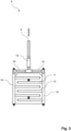
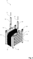
- FIGs 2 , 3 and 4 show in detail a front view ( Figure 2 ), a side view ( Figure 3 ) and a perspective view ( Figure 4 ) of the heat exchanger device 8 arranged within the gas phase part 4 of the vessel 2 of the apparatus 1.
- the vertical arranged heat exchanger device 8 comprises a system of feeding tubes 19, which has the inlet 9 for feeding coolant to the feeding tubes 19.
- the feeding tubes 19 are arranged partly vertical and partly horizontal and merge into each other.
- the vertical arranged heat exchanger device 8 comprises a system of discharging tubes 20, which has the outlet 10 for discharging coolant from the discharging tubes 20.
- the discharging tubes 20 are arranged partly vertical and partly horizontal and merge into each other.
- the heat exchanger device 8 further comprises a system of cooling tubes 11, which are arranged horizontally and merge into the lower part of the vertically arranged feeding tubes 19 and discharging tubes 20.
- the feeding tubes 19 are configured to feed the coolant to the cooling tubes 11, whilst the discharging tubes 20 are configured to discharge the coolant from the cooling tubes 11.
- the heat exchanger device further comprises a plurality of fins 12, which are arranged in a stack and wherein within the stack, adjacent fins are spaced apart from each other.
- the cooling tubes 11 extend partially through recesses in the fins 12.
- the cooling tubes 11 and the fins 12 form the heat transfer elements of the heat exchanger device 8.
- the cooling tubes 11 expand horizontally, whilst the fins 12 expand vertically in their main expansion direction.
- the cooling tubes 11 expand perpendicular to the main expansion direction of the fins 12. Due to the horizontal arrangement of the cooling tubes 11 and vertical arrangement of the fins 12, condensable components which condense on the surface of the cooling tubes and/or fins are returned by the effect of gravity from the gas phase part 4 of the vessel 2 to the liquid phase part 3 of the vessel 2.
- the fins 12 are spaced apart from each other such that a minimum distance is defined between two adjacent fins 12, wherein said minimum distance is dimensioned such that no capillary forces can occur between adjacent fins such that a condensable liquid, in particular water, cannot rise upwards between two adjacent fins against the action of gravity.
- this provides the maximum possible heat transfer surface, and on the other hand, it ensures rapid drainage of the condensed liquid by avoiding the trapping of condensed liquid between two adjacent fins. Trapped liquid between two adjacent fins would cover parts of the surface of the heat exchanger device and thus reduce the overall efficiency of the heat exchanger device.
- FIG. 5 shows a simplified block flow diagram for an electrolysis arrangement 36 according to the invention.
- the electrolysis arrangement 36 is configured to perform an alkaline water electrolysis to produce oxygen and hydrogen as the product gases.
- the electrolysis arrangement comprises an electrolysis cell stack 22, which is supplied with direct current (indicated by the combined solid and dashed line) by means of a direct current source 21.
- the electrolysis cell stack 22 comprises an anode section 23 and a cathode section 24.
- the anode section 23 and the cathode section 24 are shown as one cell, but actually comprise a plurality of cells.
- product gases are generated from the liquid electrolysis medium, which is a concentrated (e.g.
- Oxygen is generated on the anode side 23 of the electrolysis cell stack 22 and hydrogen is generated on the cathode side 24 of the electrolysis cell stack 22 from the water contained in the liquid electrolysis medium.
- a product gas loaded anolyte stream 28 is withdrawn from the anode section 23 of the electrolysis cell stack and a product gas loaded catholyte stream 30 is withdrawn from the cathode section 24 of the electrolysis cell stack 22.
- stream 28 is an oxygen loaded anolyte stream and stream 30 is a hydrogen loaded catholyte stream.
- Streams 28 and 30 are two-phase system, containing the gaseous product gas and the liquid electrolysis medium.
- the electrolysis arrangement 36 further comprises on its anode side and cathode side a combined gas-liquid separator and gas cooling device 35.
- the combined gas-liquid separator and gas cooling devices 35 each comprise an apparatus 1 with a vessel 2 as described in detail above.
- the combined gas-liquid separator and gas cooling devices 35 each comprise a lower liquid phase part 3, an upper gas phase part 4 and a heat exchanger device 8.
- the product gases oxygen and hydrogen are separated from the liquid electrolysis medium of the loaded anolyte stream 28 and the loaded catholyte stream 30 in the combined gas-liquid separator and gas cooling devices 35 respectively.
- the separated product gases are dried by means of the heat exchanger devices 8 arranged within the gas phase parts of the devices 35 by means of condensation of liquid entrained in the respective product gas, and said condensed liquid flows back to the liquid phase part 3 of the respective device 35.
- a dried oxygen stream 33 is withdrawn from the device 35 on the anode side of the electrolysis arrangement 36
- a dried hydrogen stream 34 is withdrawn from the device 35 on the cathode side of the electrolysis arrangement 36.
- the product gas-loaded streams 28 and 30 are introduced into the device 35 via an inlet in the gas phase part 4 of the respective device 35. This allows the gas loaded stream to flow freely into the device 35.
- the streams depleted in product gases i.e. on the anode side the anolyte stream 29 depleted in oxygen and on the cathode side the catholyte stream 31 depleted in hydrogen, are on the other hand withdrawn from the respective devices 35 in the sump area within the liquid phase part 3 of the devices 35. This maximizes the residence time for the electrolysis medium in the respective device 35 and thus makes the separation of the product gas as efficient as possible.
- the electrolysis arrangement 36 also comprises a circulation pump 27 on the anode side and the cathode side of the arrangement 36 respectively.
- the circulation pumps circulate the loaded and depleted electrolysis media between the electrolysis cell stack 22 and the respective devices 35.
- the oxygen depleted anolyte stream 29 and the hydrogen depleted catholyte stream 31 are merged to a mixed electrolyte stream 32. This compensates for concentration differences in the lye concentration of the anolyte stream 29 and the catholyte stream 31. These concentration differences result solely from the stoichiometrically different consumption of water on the cathode and anode sides of such a system.
- the mixed electrolyte stream 32 is heated or cooled, depending on the process conditions and the operating mode of the electrolysis arrangement 36, to a target temperature determined for the electrolysis medium at the inlet of the electrolysis cell stack 22 by means of a temperature control device 25.
- the temperature controlled mixed electrolyte stream is afterwards equally split and supplied to the anode section 23 and the cathode section 24 of the electrolysis cell stack 22 respectively.
- the temperature control device 25 can optionally be omitted.
- the electrolysis arrangement 36 further comprises a water supply 26, to supply water to the electrolysis arrangement 36 via the combined gas-liquid separator and gas cooling device 35 on the cathode side of the arrangement 36.
- the purpose of the water supply 26 is to supply the arrangement 36 with the amount of water per unit of time that is consumed per unit of time by the electrochemical reaction in the electrolysis cell stack 22.
Landscapes
- Chemical & Material Sciences (AREA)
- Engineering & Computer Science (AREA)
- Chemical Kinetics & Catalysis (AREA)
- Electrochemistry (AREA)
- Materials Engineering (AREA)
- Metallurgy (AREA)
- Organic Chemistry (AREA)
- Environmental & Geological Engineering (AREA)
- Analytical Chemistry (AREA)
- General Chemical & Material Sciences (AREA)
- Oil, Petroleum & Natural Gas (AREA)
- Sustainable Development (AREA)
- Life Sciences & Earth Sciences (AREA)
- Inorganic Chemistry (AREA)
- Health & Medical Sciences (AREA)
- Biomedical Technology (AREA)
- Physics & Mathematics (AREA)
- Thermal Sciences (AREA)
- Electrolytic Production Of Non-Metals, Compounds, Apparatuses Therefor (AREA)
Priority Applications (4)
| Application Number | Priority Date | Filing Date | Title |
|---|---|---|---|
| EP22162399.4A EP4245887A1 (de) | 2022-03-16 | 2022-03-16 | Vorrichtung zum abscheiden eines produktgases aus einem elektrolysemedium |
| CN202310162439.3A CN116770343A (zh) | 2022-03-16 | 2023-02-23 | 用于从电解介质中分离产物气体的设备 |
| AU2023201104A AU2023201104A1 (en) | 2022-03-16 | 2023-02-24 | Apparatus for separating a product gas from an electrolysis medium |
| US18/122,468 US20230295824A1 (en) | 2022-03-16 | 2023-03-16 | Apparatus for separating a product gas from an electrolysis medium |
Applications Claiming Priority (1)
| Application Number | Priority Date | Filing Date | Title |
|---|---|---|---|
| EP22162399.4A EP4245887A1 (de) | 2022-03-16 | 2022-03-16 | Vorrichtung zum abscheiden eines produktgases aus einem elektrolysemedium |
Publications (1)
| Publication Number | Publication Date |
|---|---|
| EP4245887A1 true EP4245887A1 (de) | 2023-09-20 |
Family
ID=80785295
Family Applications (1)
| Application Number | Title | Priority Date | Filing Date |
|---|---|---|---|
| EP22162399.4A Pending EP4245887A1 (de) | 2022-03-16 | 2022-03-16 | Vorrichtung zum abscheiden eines produktgases aus einem elektrolysemedium |
Country Status (4)
| Country | Link |
|---|---|
| US (1) | US20230295824A1 (de) |
| EP (1) | EP4245887A1 (de) |
| CN (1) | CN116770343A (de) |
| AU (1) | AU2023201104A1 (de) |
Families Citing this family (3)
| Publication number | Priority date | Publication date | Assignee | Title |
|---|---|---|---|---|
| EP4570955A1 (de) * | 2023-12-12 | 2025-06-18 | TotalEnergies OneTech | Wasserelektrolysezelle, zugehöriger stapel von wasserelektrolysezellen und verfahren |
| BE1032215B1 (nl) * | 2024-04-18 | 2025-07-07 | Integrate Bvba | Inrichting en werkwijze voor het thermo-elektrisch drogen van een gasvormige stroom |
| CN118497790A (zh) * | 2024-05-08 | 2024-08-16 | 中国华能集团清洁能源技术研究院有限公司 | 一种废水产氢反应器及方法 |
Citations (4)
| Publication number | Priority date | Publication date | Assignee | Title |
|---|---|---|---|---|
| CN205316367U (zh) * | 2015-12-26 | 2016-06-15 | 南京伟皓环保科技有限公司 | 一种气液分离冷却式烟气冷却装置 |
| WO2021144594A1 (en) * | 2020-01-17 | 2021-07-22 | Itm Power (Trading) Limited | Electrochemical cell plant |
| CN114086204A (zh) * | 2021-12-10 | 2022-02-25 | 清华四川能源互联网研究院 | 一种电解槽阵列系统与电解水系统控制方法 |
| CN114087904A (zh) * | 2021-12-22 | 2022-02-25 | 清华大学 | 电制氢余热利用装置和方法 |
-
2022
- 2022-03-16 EP EP22162399.4A patent/EP4245887A1/de active Pending
-
2023
- 2023-02-23 CN CN202310162439.3A patent/CN116770343A/zh active Pending
- 2023-02-24 AU AU2023201104A patent/AU2023201104A1/en active Pending
- 2023-03-16 US US18/122,468 patent/US20230295824A1/en active Pending
Patent Citations (4)
| Publication number | Priority date | Publication date | Assignee | Title |
|---|---|---|---|---|
| CN205316367U (zh) * | 2015-12-26 | 2016-06-15 | 南京伟皓环保科技有限公司 | 一种气液分离冷却式烟气冷却装置 |
| WO2021144594A1 (en) * | 2020-01-17 | 2021-07-22 | Itm Power (Trading) Limited | Electrochemical cell plant |
| CN114086204A (zh) * | 2021-12-10 | 2022-02-25 | 清华四川能源互联网研究院 | 一种电解槽阵列系统与电解水系统控制方法 |
| CN114087904A (zh) * | 2021-12-22 | 2022-02-25 | 清华大学 | 电制氢余热利用装置和方法 |
Also Published As
| Publication number | Publication date |
|---|---|
| US20230295824A1 (en) | 2023-09-21 |
| CN116770343A (zh) | 2023-09-19 |
| AU2023201104A1 (en) | 2023-10-05 |
Similar Documents
| Publication | Publication Date | Title |
|---|---|---|
| US20230295824A1 (en) | Apparatus for separating a product gas from an electrolysis medium | |
| CN113215592B (zh) | 一种大型碱性电解水制氢装置的综合热管理系统 | |
| US4344850A (en) | Fuel cell power plant coolant cleaning system and method | |
| JP7486212B2 (ja) | 液体の脱気手段および方法 | |
| CN108352550A (zh) | 带冷凝-蒸发装置燃料电池系统并行冷凝蒸发方法和装置及带冷凝-蒸发装置染料电池系统 | |
| EP4056734A1 (de) | Elektrolysesystem für wasserelektrolyse und verfahren dafür | |
| EP2491610B1 (de) | Rekombinator für eine batterie mir flüssigem elektrolyt | |
| JP4959112B2 (ja) | 燃料電池システム | |
| CN218465958U (zh) | 一种碱性水电解制氢余热利用设备 | |
| CN221588711U (zh) | 换热分离结构和水电解制氢设备 | |
| CN117587428A (zh) | 阴阳两极分离的电解海水制氢系统和方法 | |
| CN116002795B (zh) | 余热回收及废水处理系统 | |
| US7611794B2 (en) | Water controller system for direct methanol fuel cell | |
| CN213966566U (zh) | 一种反应釜、反应系统 | |
| CN222648133U (zh) | 一种电解水脱氧装置 | |
| CN212818628U (zh) | 用于制氢系统的气液分离装置 | |
| EP0069763B1 (de) | Reinigungssystem und -verfahren für kühlmittel eines brennstoffzellenkraftwerkes | |
| JP5092959B2 (ja) | 燃料電池コージェネレーションシステム | |
| CN222411888U (zh) | 制氢处理装置和制氢系统 | |
| CN224077550U (zh) | 电解水制氢系统 | |
| CN223576606U (zh) | 电解系统 | |
| CN118028901A (zh) | 一种电解水脱氧装置 | |
| AU2012365474B2 (en) | A liquid electrolyte fuel cell system | |
| CN215063147U (zh) | 一种氢氰酸反应器冷却循环系统 | |
| JP2015103417A (ja) | 燃料電池発電装置 |
Legal Events
| Date | Code | Title | Description |
|---|---|---|---|
| PUAI | Public reference made under article 153(3) epc to a published international application that has entered the european phase |
Free format text: ORIGINAL CODE: 0009012 |
|
| STAA | Information on the status of an ep patent application or granted ep patent |
Free format text: STATUS: THE APPLICATION HAS BEEN PUBLISHED |
|
| AK | Designated contracting states |
Kind code of ref document: A1 Designated state(s): AL AT BE BG CH CY CZ DE DK EE ES FI FR GB GR HR HU IE IS IT LI LT LU LV MC MK MT NL NO PL PT RO RS SE SI SK SM TR |
|
| STAA | Information on the status of an ep patent application or granted ep patent |
Free format text: STATUS: REQUEST FOR EXAMINATION WAS MADE |
|
| 17P | Request for examination filed |
Effective date: 20240320 |
|
| RBV | Designated contracting states (corrected) |
Designated state(s): AL AT BE BG CH CY CZ DE DK EE ES FI FR GB GR HR HU IE IS IT LI LT LU LV MC MK MT NL NO PL PT RO RS SE SI SK SM TR |