EP4245924A1 - Höhenverstellungsvorrichtung für ein mobilfundament und mobilfundamentvorrichtung - Google Patents
Höhenverstellungsvorrichtung für ein mobilfundament und mobilfundamentvorrichtung Download PDFInfo
- Publication number
- EP4245924A1 EP4245924A1 EP23161452.0A EP23161452A EP4245924A1 EP 4245924 A1 EP4245924 A1 EP 4245924A1 EP 23161452 A EP23161452 A EP 23161452A EP 4245924 A1 EP4245924 A1 EP 4245924A1
- Authority
- EP
- European Patent Office
- Prior art keywords
- mobile foundation
- rod
- tube
- support surface
- height adjustment
- Prior art date
- Legal status (The legal status is an assumption and is not a legal conclusion. Google has not performed a legal analysis and makes no representation as to the accuracy of the status listed.)
- Granted
Links
Images

Classifications
-
- E—FIXED CONSTRUCTIONS
- E02—HYDRAULIC ENGINEERING; FOUNDATIONS; SOIL SHIFTING
- E02D—FOUNDATIONS; EXCAVATIONS; EMBANKMENTS; UNDERGROUND OR UNDERWATER STRUCTURES
- E02D27/00—Foundations as substructures
-
- A—HUMAN NECESSITIES
- A47—FURNITURE; DOMESTIC ARTICLES OR APPLIANCES; COFFEE MILLS; SPICE MILLS; SUCTION CLEANERS IN GENERAL
- A47B—TABLES; DESKS; OFFICE FURNITURE; CABINETS; DRAWERS; GENERAL DETAILS OF FURNITURE
- A47B91/00—Feet for furniture in general
- A47B91/005—Support bases
-
- F—MECHANICAL ENGINEERING; LIGHTING; HEATING; WEAPONS; BLASTING
- F16—ENGINEERING ELEMENTS AND UNITS; GENERAL MEASURES FOR PRODUCING AND MAINTAINING EFFECTIVE FUNCTIONING OF MACHINES OR INSTALLATIONS; THERMAL INSULATION IN GENERAL
- F16M—FRAMES, CASINGS OR BEDS OF ENGINES, MACHINES OR APPARATUS, NOT SPECIFIC TO ENGINES, MACHINES OR APPARATUS PROVIDED FOR ELSEWHERE; STANDS; SUPPORTS
- F16M11/00—Stands or trestles as supports for apparatus or articles placed thereon ; Stands for scientific apparatus such as gravitational force meters
- F16M11/20—Undercarriages with or without wheels
- F16M11/24—Undercarriages with or without wheels changeable in height or length of legs, also for transport only, e.g. by means of tubes screwed into each other
-
- A—HUMAN NECESSITIES
- A47—FURNITURE; DOMESTIC ARTICLES OR APPLIANCES; COFFEE MILLS; SPICE MILLS; SUCTION CLEANERS IN GENERAL
- A47B—TABLES; DESKS; OFFICE FURNITURE; CABINETS; DRAWERS; GENERAL DETAILS OF FURNITURE
- A47B81/00—Cabinets or racks specially adapted for other particular purposes, e.g. for storing guns or skis
-
- A—HUMAN NECESSITIES
- A47—FURNITURE; DOMESTIC ARTICLES OR APPLIANCES; COFFEE MILLS; SPICE MILLS; SUCTION CLEANERS IN GENERAL
- A47B—TABLES; DESKS; OFFICE FURNITURE; CABINETS; DRAWERS; GENERAL DETAILS OF FURNITURE
- A47B91/00—Feet for furniture in general
- A47B91/02—Adjustable feet
-
- E—FIXED CONSTRUCTIONS
- E02—HYDRAULIC ENGINEERING; FOUNDATIONS; SOIL SHIFTING
- E02D—FOUNDATIONS; EXCAVATIONS; EMBANKMENTS; UNDERGROUND OR UNDERWATER STRUCTURES
- E02D27/00—Foundations as substructures
- E02D27/32—Foundations for special purposes
-
- E—FIXED CONSTRUCTIONS
- E02—HYDRAULIC ENGINEERING; FOUNDATIONS; SOIL SHIFTING
- E02D—FOUNDATIONS; EXCAVATIONS; EMBANKMENTS; UNDERGROUND OR UNDERWATER STRUCTURES
- E02D27/00—Foundations as substructures
- E02D27/32—Foundations for special purposes
- E02D27/42—Foundations for poles, masts or chimneys
-
- E—FIXED CONSTRUCTIONS
- E02—HYDRAULIC ENGINEERING; FOUNDATIONS; SOIL SHIFTING
- E02D—FOUNDATIONS; EXCAVATIONS; EMBANKMENTS; UNDERGROUND OR UNDERWATER STRUCTURES
- E02D35/00—Straightening, lifting, or lowering of foundation structures or of constructions erected on foundations
- E02D35/005—Lowering or lifting of foundation structures
-
- F—MECHANICAL ENGINEERING; LIGHTING; HEATING; WEAPONS; BLASTING
- F16—ENGINEERING ELEMENTS AND UNITS; GENERAL MEASURES FOR PRODUCING AND MAINTAINING EFFECTIVE FUNCTIONING OF MACHINES OR INSTALLATIONS; THERMAL INSULATION IN GENERAL
- F16H—GEARING
- F16H25/00—Gearings comprising primarily only cams, cam-followers and screw-and-nut mechanisms
- F16H25/18—Gearings comprising primarily only cams, cam-followers and screw-and-nut mechanisms for conveying or interconverting oscillating or reciprocating motions
- F16H25/20—Screw mechanisms
-
- A—HUMAN NECESSITIES
- A47—FURNITURE; DOMESTIC ARTICLES OR APPLIANCES; COFFEE MILLS; SPICE MILLS; SUCTION CLEANERS IN GENERAL
- A47G—HOUSEHOLD OR TABLE EQUIPMENT
- A47G29/00—Supports, holders, or containers for household use, not provided for in groups A47G1/00-A47G27/00 or A47G33/00
- A47G29/12—Mail or newspaper receptacles, e.g. letter-boxes; Openings in doors or the like for delivering mail or newspapers
-
- A—HUMAN NECESSITIES
- A47—FURNITURE; DOMESTIC ARTICLES OR APPLIANCES; COFFEE MILLS; SPICE MILLS; SUCTION CLEANERS IN GENERAL
- A47G—HOUSEHOLD OR TABLE EQUIPMENT
- A47G29/00—Supports, holders, or containers for household use, not provided for in groups A47G1/00-A47G27/00 or A47G33/00
- A47G29/12—Mail or newspaper receptacles, e.g. letter-boxes; Openings in doors or the like for delivering mail or newspapers
- A47G29/1201—Letter-box assemblies for apartment buildings
-
- A—HUMAN NECESSITIES
- A47—FURNITURE; DOMESTIC ARTICLES OR APPLIANCES; COFFEE MILLS; SPICE MILLS; SUCTION CLEANERS IN GENERAL
- A47G—HOUSEHOLD OR TABLE EQUIPMENT
- A47G29/00—Supports, holders, or containers for household use, not provided for in groups A47G1/00-A47G27/00 or A47G33/00
- A47G29/14—Deposit receptacles for food, e.g. breakfast, milk, or large parcels; Similar receptacles for food or large parcels with appliances for preventing unauthorised removal of the deposited articles, i.e. food or large parcels
-
- A—HUMAN NECESSITIES
- A47—FURNITURE; DOMESTIC ARTICLES OR APPLIANCES; COFFEE MILLS; SPICE MILLS; SUCTION CLEANERS IN GENERAL
- A47G—HOUSEHOLD OR TABLE EQUIPMENT
- A47G29/00—Supports, holders, or containers for household use, not provided for in groups A47G1/00-A47G27/00 or A47G33/00
- A47G29/14—Deposit receptacles for food, e.g. breakfast, milk, or large parcels; Similar receptacles for food or large parcels with appliances for preventing unauthorised removal of the deposited articles, i.e. food or large parcels
- A47G29/141—Deposit receptacles for food, e.g. breakfast, milk, or large parcels; Similar receptacles for food or large parcels with appliances for preventing unauthorised removal of the deposited articles, i.e. food or large parcels comprising electronically controlled locking means
-
- F—MECHANICAL ENGINEERING; LIGHTING; HEATING; WEAPONS; BLASTING
- F16—ENGINEERING ELEMENTS AND UNITS; GENERAL MEASURES FOR PRODUCING AND MAINTAINING EFFECTIVE FUNCTIONING OF MACHINES OR INSTALLATIONS; THERMAL INSULATION IN GENERAL
- F16M—FRAMES, CASINGS OR BEDS OF ENGINES, MACHINES OR APPARATUS, NOT SPECIFIC TO ENGINES, MACHINES OR APPARATUS PROVIDED FOR ELSEWHERE; STANDS; SUPPORTS
- F16M2200/00—Details of stands or supports
- F16M2200/08—Foot or support base
Definitions
- the invention relates to a height adjustment device for a mobile foundation, in particular for a concrete base.
- the invention relates to a mobile foundation device comprising a mobile foundation and the above height adjustment device.
- the invention further relates to a system comprising the above mobile foundation device and a packing station.
- mobile foundations - also called mobile foundations - have been used to secure the device and/or to provide a flat surface for setting up the device Device proven.
- Mobile foundations are used, among other things, as foundations for advertising billboard supports, as bases for advertising columns and/or as a base for packing stations.
- the mobile foundations are often designed as concrete building blocks and/or concrete bases, but depending on the application they can also be made from other suitable materials.
- known mobile foundations do not allow level adjustment for uneven and/or sloping ground. Accordingly, one must If the ground is uneven and/or sloping, it must first be straightened before the mobile foundation is erected, which is time-consuming and involves additional costs. In addition, it is generally no longer possible to compensate for an uneven and/or sloping surface after the mobile foundation has been set up or even after the device, such as the packing station, has been attached to the mobile foundation. In other words, known mobile foundations do not allow subsequent compensation of unevenness and/or inclinations in the ground and are therefore limited in their use.
- measures that simplify the setting up of mobile foundations on uneven and/or sloping surfaces.
- measures should be provided that enable uneven and/or sloping surfaces to be compensated after the mobile foundation has been set up and/or after a device such as a packing station has been attached to the mobile foundation.
- a mobile foundation device comprising a mobile foundation and the above height adjustment device, wherein the mobile foundation comprises a top with a support surface and a bottom side opposite the top and comprises at least one opening running perpendicular to the support surface and through to the bottom, the rod with an end facing away from the pipe projects into the opening of the mobile foundation and the support surface of the threaded plate is arranged on the underside of the mobile foundation.
- the height adjustment device allows the height of a mobile foundation to be adjusted using simple means.
- the height adjustment device has the rod and the threaded plate.
- the height of the threaded plate and thus also the height of the support surface can be adjusted via the threaded section on the rod. Since in the mobile foundation device the support surface of the threaded plate is arranged on the underside of the mobile foundation, the height of the mobile foundation relative to the ground can be changed by changing the position of the threaded plate on the threaded section.
- the weight of the mobile foundation is preferably transferred from the threaded plate via the rod to the pipe and thus to the subsoil.
- the height adjustment device allows the mobile foundation to be set up on a sloping and/or uneven surface and/or to compensate for the sloping and/or uneven surface.
- the height adjustment device has the tube that functions as a stand rail and/or base and is designed in such a way that the rod can be rotated relative to the tube at least partially about the axis parallel to the longitudinal axis of the tube.
- the fact that the rod is rotatable relative to the pipe also means, in other words, that the rod and the pipe are not connected to one another in a rotationally fixed manner, but rather that the rod is in relation to the pipe and/or the pipe in Reference to the rod is movable and in particular rotatable.
- the tube provides the cavity into which the rod protrudes at one end.
- the pipe has a wall recess on its outside, whereby the rod protrudes into the cavity of the pipe.
- wall recess means a recess in a side wall of the pipe and not one of two openings that may be present on the end faces of the pipe.
- the recess lies on a lateral surface of the pipe.
- the rod protrudes laterally into the pipe. Because the wall recess is on the lateral surface of the pipe and one end of the rod projects into the cavity of the pipe, a longitudinal axis of the rod is not parallel to the longitudinal axis of the pipe.
- the axis is parallel to the longitudinal axis of the tube, about which the rod is at least partially rotatable relative to the tube, and is also not parallel to the longitudinal axis of the rod.
- the at least partial rotation of the rod is not a rotation of the rod about its longitudinal axis.
- the wall recess of the tube allows the rod to have play in such a way that the rod can be moved relative to the tube at least with the rotational movement.
- the axis of rotation of this rotational movement is preferably located directly in the wall recess of the tube and runs parallel to the longitudinal axis of the tube.
- the connection between the tube and the rod is in particular such that the rod is at least partially rotatable about the axis of rotation relative to the tube.
- At least partially rotatable particularly preferably means that a rotational movement of the rod about the axis of rotation is possible relative to the tube, whereby the rotational movement does not have to be a rotational movement through a full 360 degrees.
- the magnitude of the rotational movement preferably depends on the geometry of the cavity of the tube.
- the connection between the pipe and the rod can be such that the rod can be rotated by 2 degrees relative to the pipe.
- the rod can rest obliquely in the cavity of the tube within the cavity of the tube in relation to a plane of the ground on which the tube rests as a support rail and/or base.
- the device makes it possible to compensate for the inclination of the ground. For example, it is possible in such a way that if the surface on which the pipe rests is inclined, the rod is perpendicular to the surface shows and rests obliquely in the cavity in relation to the plane of the subsurface.
- connection between the tube and the rod is such that the rod can be rotated relative to the tube by 360 degrees about a further axis of rotation, the further axis of rotation running through the wall recess of the pipe and parallel to is a normal vector of the subsurface plane.
- the rod and the tube essentially perform the function of a ball joint, whereby the height adjustment device and the mobile foundation device can be easily set up on a sloping and/or uneven surface and the inclination of the surface can be compensated for.
- the threaded section of the rod it is preferably provided that it is a section with an external thread. More preferably, the external thread is designed to correspond to an internal thread of the threaded plate. With regard to the rod, it can also be provided that the threaded section only extends over a small area of the rod. However, it is preferably provided that the threaded section extends over more than a third of the length of the rod and more preferably over more than half of the length of the rod.
- the rod is particularly preferably a threaded rod - that is, a rod which has a thread essentially over its entire length. In this way, the height of the mobile foundation can also be changed by a large amount.
- the tube comprises two mutually parallel and preferably flat outer sides and/or that the tube is designed as a rectangular tube. Accordingly, the tube can easily take on the function of the stand rail and/or the base of the height adjustment device.
- the weight of the mobile foundation is preferably transferred from the threaded plate via the rod to the pipe and in particular to the flat inside of the pipe opposite the wall recess.
- the cross section of the tube is therefore preferably rectangular and/or square. More preferably, the tube is designed as a metal tube.
- the rod comprises a device for torque transmission at an end facing away from the tube.
- a device for transmitting torque by means of positive locking can include a screw head at its end.
- the end of the rod preferably has a slot, a hole with an internal hexagon (e.g. hexagon socket), an internal spline and/or a hexalobular socket.
- the extent of the device for torque transmission is not greater than the diameter of the rod.
- the rod is a set screw.
- the device for torque transmission makes it possible in a simple manner that the position of the threaded plate is made possible by rotating the rod in relation to the non-rotatable threaded plate. Rotating the threaded plate around the non-rotatable rod can therefore preferably be dispensed with in order to adjust the height of the mobile foundation.
- the height adjustment device comprises a plurality of rods and that the tube on the outside comprises a plurality of wall recesses corresponding to the number of rods, whereby the rods protrude into the cavity.
- the height adjustment device does not just have a rod and a threaded plate, but rather a plurality of rods and a threaded plate for each rod.
- the tube preferably has a corresponding number of wall recesses, so that each rod protrudes through a wall recess into the cavity of the tube.
- the height adjustment device particularly preferably comprises two rods and two threaded plates and a tube with two wall recesses.
- the height adjustment device comprises a plurality of rods and a plurality of tubes and that the total number of wall recesses in the plurality of tubes corresponds to the number of rods.
- the plurality of rods make it possible in a particularly simple manner for a gradient in the ground to be compensated for by means of the height adjustment device, such that the mobile foundation has a support surface whose normal vector points in the plumb direction.
- gradient compensation is possible in all directions on the subsurface level - meaning the pipe does not have to be arranged in a specific direction to the gradient.
- the invention also relates to the mobile foundation device comprising the mobile foundation and the above height adjustment device.
- the task is also solved by the mobile foundation device comprising the mobile foundation and the height adjustment device, the mobile foundation comprising the top with the support surface and the bottom side opposite the top and comprising at least one opening running perpendicular to the support surface and continuous to the bottom, the height adjustment device Rod with the threaded section, the threaded plate held adjustably on the threaded section and having the support surface, and the tube having the cavity, the tube comprising at least one wall recess on the outside, whereby the rod protrudes into the cavity, the rod with the the end facing away from the pipe projects into the opening of the mobile foundation and the support surface of the threaded plate is arranged on the underside of the mobile foundation, and the height adjustment device is designed such that the rod is at least partially rotatable relative to the pipe about the axis parallel to the longitudinal axis of the pipe.
- the mobile foundation device has the advantage that after setting up the mobile foundation device on a surface, the mobile foundation device can be easily adjusted in height.
- the tube functioning as a stand rail and/or base can be rotated, as is common with furniture feet, for example.
- the height of the mobile foundation can be adjusted by turning the rod.
- turning the rod causes the position of the threaded plate, on the support surface of which the mobile foundation is arranged with its underside, to change, which also changes the height of the mobile foundation relative to the ground.
- the mobile foundation device also has the advantage in that when the mobile foundation device is set up on a surface with a slope, the support surface of the mobile foundation can be aligned in such a way that the normal vector of the support surface points in the plumb direction. In particular, gradient compensation is possible in all directions on the subsurface level.
- the tube that functions as a stand rail, and in particular the rectangular tube also has the advantage that regardless of the extent of the gradient compensation set, the contact area in the form of the support surface of the tube is always the same. Accordingly, the same surface loads are always ensured with the pipe.
- the pipe acting as a stand rail and in particular the rectangular pipe lies flat on the surface, regardless of the degree of slope of the ground.
- the mobile foundation device is designed such that the rod is displaceable relative to the mobile foundation along a direction perpendicular to the support surface, in particular by means of a rotational movement of the rod about an axial extension axis of the rod.
- the continuous opening in the mobile foundation and the diameter of the rod are preferably coordinated with one another, such that the rod is displaceable in the continuous opening along the axial extension axis and is guided in movement by the opening.
- the mobile foundation comprises a recess on the underside for non-rotatable mounting of the threaded plate.
- the threaded plate is prevented from rotating relative to the mobile foundation by positive locking with the recess. Accordingly, a rotation of the rod about the axial extension axis of the rod causes the position of the threaded plate on the rod to change, thereby changing the height of the support surface. The position of the rod relative to the mobile foundation also shifts accordingly.
- the opening of the mobile foundation which runs perpendicular to the support surface and passes through to the underside, is arranged in the recess.
- the mobile foundation comprises a further recess on the underside for sinking the pipe in the mobile foundation.
- the further recess has the advantage that the pipe functioning as a stand rail and/or base can preferably be accommodated completely in the further recess, so that in a state in which the pipe disappears into the further recess, the weight of the mobile foundation becomes significant Share is transferred to the subsoil via the underside of the mobile foundation. Only when the height of the mobile foundation is adjusted upwards from this position, preferably by changing the position of the threaded plate by turning the rod, is the underside of the mobile foundation arranged on the support surface pressed upwards and the weight of the mobile foundation is transferred over the threaded plate and the Transfer rod to pipe.
- the length of the further recess corresponds to a length of the pipe and/or extends over the entire underside of the mobile foundation. This makes it particularly easy to sink the pipe into the further recess in the mobile foundation.
- a width of the further recess corresponds to at least one width of the tube.
- the width of the recess is greater than the width of the pipe and corresponds at least to the length of a straight stretch connecting two pipe sides, wherein in a state of maximum deflection of the rod about the axis parallel to the longitudinal axis of the pipe, the stretch is perpendicular to the rod stands and connects the two pipe sides with a shortest distance.
- the mobile foundation comprises the recess on the underside for non-rotatable storage of the threaded plate relative to the mobile foundation and the further recess on the underside for sinking the pipe into the mobile foundation.
- the recess is designed as a recess in the further recess is.
- a total height of the further recess and the recess preferably corresponds to at least the sum of a height of the pipe and a thickness of the threaded plate.
- the total height is preferably measured from the lowest point on the bottom of the mobile foundation.
- a total height which preferably corresponds at least to the sum of the thickness of the threaded plate and the height of the pipe, has the advantage that the pipe can be easily sunk into the underside of the mobile foundation.
- the mobile foundation comprises a vertical extension on the top that extends along the support surface.
- the support surface is particularly preferably a flat plane, which allows another device, such as a packing station, to be arranged on the support surface.
- the vertical extension has the advantage that a device arranged on the mobile foundation is supported laterally by the extension.
- the mobile foundation comprises on the top two vertical extensions which extend on opposite sides of the support surface. These two extensions particularly preferably have different heights.
- An extension that is designed to rest at least partially on a back side of a device to be arranged on the support surface is preferably higher than an extension that is designed to rest at least partially on a front side of the device to be arranged on the support surface.
- the continuous opening runs through the vertical extension.
- the continuous opening does not run through the support surface. Since the support surface serves as a storage area for the device, the course of the continuous opening through the vertical extension has the advantage that the height of the mobile foundation can be adjusted even after the device has been set up on the support surface.
- the mobile foundation comprises fastening means which are preferably attached to the support surface and/or to the vertical extension.
- a device such as a container, a packing station or the like can be easily installed be connected to the mobile foundation and/or attached to the mobile foundation.
- the fastening means are preferably designed as internal threads. For example, particularly in the case of a mobile foundation made of concrete, threaded inserts can be cast into the mobile foundation.
- the mobile foundation can be made from any material suitable for outdoor use.
- the mobile foundation is designed as a concrete base and/or concrete building block. This represents a cost-effective way to provide a robust and heavy mobile foundation.
- the number of further recesses for sinking the pipe into the underside of the mobile foundation corresponds to the number of pipes and/or that the number of recesses for non-rotatably mounting the threaded plate corresponds to the number of threaded plates and/or Rods corresponds.
- a mobile foundation device which comprises a mobile foundation and a height adjustment device, the mobile foundation comprising the top with the support surface and the bottom side opposite the top, two further recesses for sinking the pipe into the bottom of the mobile foundation, and four perpendicular to the support surface extending opening and extending to the underside, the height adjustment device comprising four rods, each with a threaded section, four threaded plates which are each adjustable on the threaded section and have the support surface, and two tubes each having the cavity, each tube comprising two wall recesses on the outside, whereby one rod protrudes into the cavity, each rod protruding with the end facing away from the pipe into an opening in the mobile foundation, the support surfaces of the threaded plates are arranged on the underside of the mobile foundation, and the height adjustment device is designed such that each rod is relative to that tube, into whose cavity the end of the rod protrudes, can be rotated at least partially about an axis parallel to the longitudinal axis of that tube.
- the mobile foundation device therefore preferably has two tubes which function as stand rails and/or feet, each tube comprising two wall recesses for two rods. In this way, an inclination of the ground can be compensated for and the height of the mobile foundation can be changed in a particularly simple and cost-effective manner.
- the invention also relates to the system comprising the packing station and the mobile foundation device.
- the packing station is preferably arranged on the support surface of the mobile foundation.
- the vertical extension of the mobile foundation borders a rear wall of the packing station. Accordingly, the vertical extension can further stabilize the packing station.
- the packing station is attached to the mobile foundation, particularly preferably by means of the fastening means attached to the mobile foundation. It is further preferred that a bottom of the packing station is connected to the support surface and/or that the rear wall of the packing station is connected to the vertical extension.
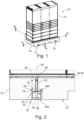
- FIG. 1 shows a schematic representation of a system 10 comprising a mobile foundation device 12 and a packing station 14.
- the mobile foundation device 12 in turn comprises a mobile foundation 16 designed in this exemplary embodiment as a concrete base 16 and a height adjustment device 18, explained in more detail below, by means of which the mobile foundation 16 can be adjusted in height is.
- Figures 2 and 3 provide sectional views through the in Figure 1 shown system 10 along the in Figure 1 lines marked A and B.
- the height adjustment device 18 has a rod 20 with a threaded section which in the present exemplary embodiment extends over the entire length of the rod 20, an adjustable support surface held on the threaded section and a support surface 22 having threaded plate 24, and a tube 28 having a cavity 26.
- the tube 28 is designed here as a rectangular tube 28 and has two mutually parallel outer sides 30a, 30b. On one of the outer sides 30a, the tube 28 includes a wall recess 32 through which the rod 20 projects into the cavity 26.
- the wall recess 32 leaves the rod 20 some play, so that the rod 20 is at least partially rotatable relative to the tube 28 about an axis 34 parallel to the longitudinal axis of the tube 28.
- the axis of rotation 34 runs directly through the wall recess 32 and lies in Figure 2 perpendicular to the drawing plane. Accordingly, the axis of rotation is 34 in Figure 2 shown as a circle with a cross.
- the rotational movement is in the Figures 2 and 3 indicated by arrow 36, where in Figure 2 the rod 20 performs a rotational movement in the plane of the drawing.
- the mobile foundation 16 also includes a top side 38 with a support surface 40 and a bottom side 42 opposite the top side 38.
- the packing station 14 is arranged on the support surface 40 and connected by means of threaded pins 44 to fasteners embedded in the mobile foundation 16 - in this case threaded inserts with an internal thread.
- the support surface 40 of the mobile foundation 16 is flanked on two sides by a vertical extension 46.
- the back of the packing station 14 is connected to the vertical extension 46 on the back with a further threaded pin 44.
- the mobile foundation 16 has openings 48 that run perpendicular to the support surface 40 and pass through to the underside 42.
- the openings 48 run through the vertical extensions 46.
- the rod 20 of the height adjustment device 18 projects into the opening 48 of the mobile foundation 16 with an end facing away from the tube 28, the support surface 22 of the threaded plate 24 being arranged on the underside 42 of the mobile foundation 16.
- the mobile foundation 16 has a recess 50 on the underside 42 for non-rotatable mounting of the threaded plate 24, which prevents the threaded plate 24 from rotating relative to the mobile foundation by positive locking 16 hinders. Furthermore, the mobile foundation 16 has further recesses 52 on the underside 42 for sinking the pipes 28 in the mobile foundation 16. How Figures 1 to 3 show, the further recesses 52 enable the tube 28, which acts as a stand rail, to be accommodated completely in the further recess 52, so that in the Figures 1 to 3 In the state shown, the weight of the mobile foundation 16 is transferred to the ground via the bottom 42 to a significant extent.
- the further recesses 52 extend over the entire underside 42 of the mobile foundation 16. Furthermore, the recesses 50 are designed as recesses in the further recesses 52 for the rotation-proof mounting of the threaded plate 24. At the location of the recess, a total height of the further recess 52 and the recess 50 also corresponds to the sum of a height of the tube 28 and a thickness of the threaded plate 24.
- FIG 4 shows a further schematic representation of a further preferred embodiment of the mobile foundation device 12 comprising the mobile foundation 16 and the height adjustment device 18.
- the mobile foundation 16 has no vertical extensions on the top 38. Instead, the entire top 38 is formed by the support surface 40.
- the height adjustment function and inclination compensation function of the height adjustment device 18 is clearly shown.
- the support surface 40 of the mobile foundation office 16 can be adjusted horizontally using the height adjustment device 18 and the difference in level can be compensated for.
- the rod 20 rests obliquely in the cavity 26 of the tube 28 in relation to the two mutually parallel outer sides 30a, 30b of the tube 28.
- connection between tube 28 and rod 20 is such that the rod 20 can be rotated by 360 degrees relative to the tube 28 about a further axis of rotation 58, which is indicated by arrow 60 is illustrated.
- the further axis of rotation 58 runs through the wall recess 32 of the tube 28 and parallel to a normal vector of the plane of the subsurface.
- the rod 20 comprises a device for torque transmission 62 by means of positive locking at the end facing away from the tube 28 - in this case a hole with a hexagon socket.
- Reference symbol list system 10 Mobile foundation device 12 packing station 14 Mobile foundation, concrete base 16 Height adjustment device 18 pole 20 Support surface 22 Threaded plate 24 cavity 26 tube, rectangular tube 28 Outside 30 Wall recess 32 Axis of rotation 34 Arrow, rotation movement 36 Top 38 Support surface 40 bottom 42 Set screw 44 vertical extension 46 opening 48 recess 50 further recess 52 axial extension axis of the rod 54 Arrow, rotation movement 56 Another axis of rotation 58 Arrow, rotation movement 60 Torque transmission device 62
Landscapes
- Engineering & Computer Science (AREA)
- General Engineering & Computer Science (AREA)
- Structural Engineering (AREA)
- Life Sciences & Earth Sciences (AREA)
- General Life Sciences & Earth Sciences (AREA)
- Mining & Mineral Resources (AREA)
- Paleontology (AREA)
- Civil Engineering (AREA)
- Mechanical Engineering (AREA)
- Legs For Furniture In General (AREA)
- Foundations (AREA)
- Sewage (AREA)
Abstract
- eine Stange (20) mit einem Gewindeabschnitt,
- eine auf dem Gewindeabschnitt verstellbar gehaltene und eine Abstützfläche (22) aufweisende Gewindeplatte (24), und
- ein einen Hohlraum (26) aufweisendes Rohr (28),
wobei das Rohr (28) bei einer Außenseite (30) wenigstens eine Wandaussparung (32) umfasst, wodurch die Stange (20) in den Hohlraum (26) ragt, und wobei die Höhenverstellungsvorrichtung (18) derart ausgestaltet ist, dass die Stange (20) relativ zum Rohr (28) wenigstens anteilig um eine Achse (34) parallel zur Längsachse des Rohres (28) drehbar ist.
Description
- Die Erfindung betrifft eine Höhenverstellungsvorrichtung für ein Mobilfundament, insbesondere für einen Betonsockel.
- Zudem betrifft die Erfindung eine Mobilfundamentvorrichtung umfassend ein Mobilfundament und die obige Höhenverstellungsvorrichtung.
- Weiterhin betrifft die Erfindung ein System umfassend die obige Mobilfundamentvorrichtung und eine Packstation.
- Wenn Vorrichtungen wie Container, Werbetafelträger oder Packstationen im Außenraum aufgestellt werden, ist es notwendig diese vor Diebstahl und/oder vor einem Umkippen durch Wind zu schützen. Dies kann beispielsweise über geeignete Verankerungen im Untergrund erfolgen. Insbesondere wenn die Vorrichtungen lediglich temporär aufgestellt werden sollen und/oder wenn der Untergrund es nicht erlaubt die Vorrichtung direkt im Untergrund zu verankern, haben sich mobile Fundamente - auch Mobilfundamente genannt - zur Sicherung der Vorrichtung und/oder zur Bereitstellung eines planen Untergrundes zum Aufstellen der Vorrichtung bewährt. Mobilfundamente finden unter anderem Anwendung als Fundamente für Werbetafelträger, als Sockel für Litfaßsäulen und/oder als Untergrund für Packstationen.
- Oftmals sind die Mobilfundamente als Betonbausteine und/oder Betonsockel ausgestaltet, können aber je nach Anwendungsfall auch aus anderen geeigneten Materialien gefertigt sein.
- Nachteilig an bekannten Mobilfundamenten ist, dass diese keinen Niveauausgleich für einen unebenen und/oder schrägen Untergrund erlauben. Entsprechend muss bei einem unebenen und/oder schrägen Untergrund dieser vor Aufstellung des Mobilfundamentes erst begradigt werden, was aufwändig ist und mit zusätzlichen Kosten verbunden ist. Zudem kann in der Regel ein Ausgleichen eines unebenen und/oder schrägen Untergrundes nicht mehr nach dem Aufstellen des Mobilfundamentes oder sogar nach Anbringen der Vorrichtung, wie der Packstation, auf dem Mobilfundament erfolgen. In anderen Worten erlauben bekannte Mobilfundamente kein nachträgliches Ausgleichen von Unebenheiten und/oder Neigungen des Untergrundes und sind somit in ihrem Einsatz beschränkt.
- Ausgehend von dieser Situation ist es Aufgabe der vorliegenden Erfindung, Maßnahmen bereitzustellen, die das Aufstellen von Mobilfundamenten auf unebenen und/oder schrägen Untergründen vereinfachen. Insbesondere sollen Maßnahmen bereitgestellt werden, die ein Ausgleichen von unebenen und/oder schrägen Untergründen nach Aufstellen des Mobilfundamentes und/oder nach Anbringen einer Vorrichtung wie eine Packstation auf dem Mobilfundament ermöglichen.
- Die Aufgabe der Erfindung wird durch die Merkmale der unabhängigen Ansprüche gelöst. Vorteilhafte Ausgestaltungen sind in den Unteransprüchen angegeben.
- Demnach wird die Aufgabe gelöst durch eine Höhenverstellungsvorrichtung für ein Mobilfundament, umfassend
- eine Stange mit einem Gewindeabschnitt,
- eine auf dem Gewindeabschnitt verstellbar gehaltene und eine Abstützfläche aufweisende Gewindeplatte, und
- ein einen Hohlraum aufweisendes Rohr,
- Weiterhin wird die Aufgabe durch eine Mobilfundamentvorrichtung umfassend ein Mobilfundament und die obige Höhenverstellungsvorrichtung gelöst, wobei das Mobilfundament eine Oberseite mit einer Auflagefläche und eine der Oberseite gegenüberliegende bodenseitige Unterseite umfasst und wenigstens eine senkrecht zur Auflagefläche verlaufende und zur Unterseite durchgehende Öffnung umfasst, wobei die Stange mit einem dem Rohr abgewandten Ende in die Öffnung des Mobilfundamentes ragt und die Abstützfläche der Gewindeplatte an der Unterseite des Mobilfundamentes angeordnet ist.
- Zudem wird die Aufgabe durch ein System umfassend eine Packstation und die obige Mobilfundamentvorrichtung gelöst.
- Ein Aspekt der Erfindung ist, dass die Höhenverstellungsvorrichtung mit einfachen Mitteln erlaubt, ein Mobilfundament in seiner Höhe zu verstellen. Zur Verbindung der Höhenverstellungsvorrichtung mit dem Mobilfundament weist die Höhenverstellungsvorrichtung die Stange und die Gewindeplatte auf. Über den Gewindeabschnitt an der Stange lässt sich die Höhe der Gewindeplatte und damit auch die Höhe der Abstützfläche einstellen. Da bei der Mobilfundamentvorrichtung die Abstützfläche der Gewindeplatte an der Unterseite des Mobilfundamentes angeordnet ist, lässt sich somit durch Verändern der Lage der Gewindeplatte am Gewindeabschnitt die Höhe des Mobilfundamentes zum Untergrund verändern. Bevorzugt wird das Gewicht des Mobilfundamentes von der Gewindeplatte über die Stange auf das Rohr und somit den Untergrund geleitet. Diesbezüglich ist bevorzugt vorgesehen, dass das in den Hohlraum des Rohres ragende Ende der Stange auf einer der Aussparung gegenüberliegenden Innenseite des Rohres ruht.
- Ein weiterer Aspekt der Erfindung ist, dass die Höhenverstellungsvorrichtung erlaubt, das Mobilfundament auf einem schrägen und/oder unebenen Untergrund aufzustellen und/oder den schrägen und/oder unebenen Untergrund auszugleichen. Dafür weist die Höhenverstellungsvorrichtung das als Standschiene und/oder Standfuß fungierende Rohr auf und ist derart ausgestaltet, dass die Stange relativ zum Rohr wenigstens anteilig um die Achse parallel zur Längsachse des Rohres drehbar ist. Dass die Stange relativ zum Rohr drehbar ist, bedeutet in anderen Worten auch, dass die Stange und das Rohr nicht drehfest miteinander verbunden sind, sondern dass die Stange in Bezug zum Rohr und/oder das Rohr in Bezug zur Stange bewegbar und insbesondere rotierbar ist. Das Rohr stellt den Hohlraum bereit, in den die Stange mit einem Ende hineinragt. Dafür weist das Rohr auf seiner Außenseite die Wandaussparung auf, wodurch die Stange in den Hohlraum des Rohres ragt. Mit Wandaussparung ist vorliegend eine Aussparung in einer Seitenwand des Rohres gemeint und nicht eine von zwei sich eventuell an den Stirnseiten des Rohres vorhandenen Öffnungen. In anderen Worten liegt die Aussparung also auf einer Mantelfläche des Rohres. In noch anderen Worten ragt die Stange also seitlich in das Rohr hinein. Dadurch, dass die Wandaussparung auf der Mantelfläche des Rohres ist und die Stange mit einem Ende in den Hohlraum des Rohres ragt, ist eine Längsachse der Stange nicht parallel zur Längsachse des Rohres. Zudem ist dadurch die Achse parallel zur Längsachse des Rohres, um die die Stange relativ zum Rohr wenigstens anteilig drehbar ist, auch nicht parallel zur Längsachse der Stange. In andern Worten ist die wenigstens anteilige Drehung der Stange also keine Drehung der Stange um ihre Längsachse.
- Besonders bevorzugt ermöglicht die Wandaussparung des Rohres, wodurch die Stange in den Hohlraum ragt, der Stange ein Spiel, derart dass die Stange relativ zum Rohr wenigstens mit der Drehbewegung bewegbar ist. Die Drehachse dieser Drehbewegung liegt bevorzugt direkt in der Wandaussparung des Rohres und verläuft parallel zur Längsachse des Rohres. Die Verbindung zwischen Rohr und Stange ist insbesondere derart, dass die Stange relativ zum Rohr wenigstens anteilig um die Drehachse drehbar ist. Wenigstens anteilig drehbar bedeutet besonders bevorzugt, dass relativ zum Rohr eine Rotationsbewegung der Stange um die Drehachse möglich ist, wobei die Rotationsbewegung nicht eine Rotationsbewegung um volle 360 Grad sein muss. Die Größe der Rotationsbewegung hängt bevorzugt von der Geometrie des Hohlraums des Rohres ab. Beispielsweise kann die Verbindung zwischen Rohr und Stange derart sein, dass eine Rotation der Stange relativ zum Rohr um 2 Grad möglich ist.
- In anderen Worten kann die Stange also innerhalb des Hohlraums des Rohres in Bezug zu einer Ebene des Untergrundes, auf dem das Rohr als Standschiene und/oder Standfuß ruht, schräg in dem Hohlraum des Rohres ruhen. Derart ermöglicht die Vorrichtung eine Neigung des Untergrundes auszugleichen. Beispielsweise ist es derart möglich, dass bei einem geneigten Untergrund, auf dem das Rohr aufliegt, die Stange in Lotrichtung zum Untergrund zeigt und entsprechend in Bezug zur Ebene des Untergrundes schräg im Hohlraum ruht.
- In einer weiteren bevorzugten Weiterbildung der Erfindung ist bevorzugt vorgesehen, dass die Verbindung zwischen Rohr und Stange derart ist, dass die Stange relativ zum Rohr um 360 Grad um eine weitere Drehachse drehbar ist, wobei die weitere Drehachse durch die Wandaussparung des Rohres verläuft und parallel zu einem Normalenvektor der Ebene des Untergrundes ist. Bevorzugt ist in anderen Worten also vorgesehen, dass die Stange und das Rohr im Wesentlichen die Funktion eines Kugelgelenkes erbringen, wodurch die Höhenverstellungsvorrichtung und die Mobilfundamentvorrichtung problemlos auf einem schrägen und/oder unebenen Untergrund aufgestellt werden können und die Neigung des Untergrundes ausgeglichen werden kann.
- Im Hinblick auf den Gewindeabschnitt der Stange ist bevorzugt vorgesehen, dass es sich um einen Abschnitt mit einem Außengewinde handelt. Weiter bevorzugt ist das Außengewinde korrespondierend zu einem Innengewinde der Gewindeplatte ausgestaltet. Im Hinblick auf die Stange kann zudem vorgesehen sein, dass sich der Gewindeabschnitt lediglich über einen kleinen Bereich der Stange erstreckt. Bevorzugt ist allerdings vorgesehen, dass der Gewindeabschnitt sich über mehr als ein Drittel der Länge der Stange und weiter bevorzugt über mehr als die Hälfte der Länge der Stange erstreckt. Besonders bevorzugt handelt es sich bei der Stange um eine Gewindestange - also eine Stange die im Wesentlichen über ihre gesamte Länge ein Gewinde aufweist. Derart lässt sich auch die Höhe des Mobilfundamentes um einen großen Betrag verändern.
- In Bezug zum Rohr ist gemäß einer weiteren bevorzugten Weiterbildung der Erfindung vorgesehen, dass das Rohr zwei zueinander parallele und bevorzugt plane Außenseiten umfasst und/oder dass das Rohr als Rechteckrohr ausgestaltet ist. Entsprechend kann das Rohr auf einfache Weise die Funktion der Standschiene und/oder des Standfußes der Höhenverstellungsvorrichtung übernehmen. Bevorzugt wird das Gewicht des Mobilfundamentes von der Gewindeplatte über die Stange auf das Rohr und insbesondere auf die der Wandaussparung gegenüberliegende plane Innenseite des Rohres übertragen. Besonders bevorzugt ist also der Querschnitt des Rohres rechteckig und/oder quadratisch. Weiter bevorzugt ist das Rohr als Metallrohr ausgestaltet.
- Gemäß einer weiteren bevorzugten Weiterbildung der Erfindung ist vorgesehen, dass die Stange an einem dem Rohr abgewandten Ende eine Einrichtung zur Drehmomentübertragung umfasst. Bevorzugt handelt es sich dabei um eine Einrichtung zur Drehmomentübertragung mittels Formschluss. Beispielsweise kann die Stange an ihrem Ende einen Schraubenkopf umfassen. Bevorzugt besitzt das Ende der Stange einen Schlitz, ein Loch mit einem Innen-n-kant (bspw. Innensechskant), einem Innenvielzahn und/oder einem Innensechsrund. Bevorzugt ist die Einrichtung zur Drehmomentübertragung in ihrer Ausdehnung nicht größer als der Durchmesser der Stange. Weiter bevorzugt handelt es sich bei der Stange um einen Gewindestift. Die Einrichtung zur Drehmomentübertragung ermöglicht derart auf einfache Weise, dass die Lage der Gewindeplatte durch Drehen der Stange in Bezug zur drehfesten Gewindeplatte ermöglicht wird. Auf ein Drehen der Gewindeplatte um die drehfeste Stange kann also zum Verstellen der Höhe des Mobilfundamentes bevorzugt verzichtet werden.
- Gemäß einer weiteren bevorzugten Weiterbildung der Erfindung ist vorgesehen, dass die Höhenverstellungsvorrichtung eine Mehrzahl an Stangen umfasst und dass das Rohr auf der Außenseite mehrere zur Anzahl an Stangen korrespondierende Wandaussparungen umfasst, wodurch die Stangen in den Hohlraum ragen. Besonders bevorzugt weise die Höhenverstellungsvorrichtung also nicht lediglich eine Stange und eine Gewindeplatte auf, sondern eine Mehrzahl an Stangen und für jede Stange eine Gewindeplatte. Das Rohr weist bevorzugt eine dazu korrespondierende Anzahl an Wandaussparungen auf, so dass jeweils eine Stange durch eine Wandaussparung in den Hohlraum des Rohres hineinragt. Besonders bevorzugt umfasst die Höhenverstellungsvorrichtung zwei Stangen und zwei Gewindeplatten und ein Rohr mit zwei Wandaussparungen. Weiter bevorzugt kann vorgesehen sein, dass die Höhenverstellungsvorrichtung eine Mehrzahl an Stangen und eine Mehrzahl an Rohren umfasst und dass die Gesamtzahl an Wandaussparungen bei der Mehrzahl an Rohren zu der Anzahl an Stangen korrespondiert.
- Die Mehrzahl an Stangen, und besonders bevorzugt zwei Stangen in einem Rohr, ermöglichen auf besonders einfache Weise, dass mittels der Höhenverstellungsvorrichtung ein Gefälle des Untergrundes ausgeglichen wird, derart dass das Mobilfundament eine Auflagefläche aufweist, deren Normalenvektor in Lotrichtung weist. Insbesondere ist der Gefälleausgleich in alle Richtungen in der Ebene des Untergrundes möglich - spricht das Rohr muss also nicht in eine spezifische Richtung zum Gefälle angeordnet werden.
- Wie bereits erwähnt betrifft die Erfindung auch die Mobilfundamentvorrichtung umfassend das Mobilfundament und die obige Höhenverstellungsvorrichtung. Die Aufgabe wird also auch gelöst von der Mobilfundamentvorrichtung umfassend das Mobilfundament und die Höhenverstellungsvorrichtung, wobei das Mobilfundament die Oberseite mit der Auflagefläche und die der Oberseite gegenüberliegende bodenseitige Unterseite umfasst und wenigstens eine senkrecht zur Auflagefläche verlaufende und zur Unterseite durchgehende Öffnung umfasst, wobei die Höhenverstellungsvorrichtung die Stange mit dem Gewindeabschnitt, die auf dem Gewindeabschnitt verstellbar gehaltene und die Abstützfläche aufweisende Gewindeplatte, und das den Hohlraum aufweisende Rohr umfasst, wobei das Rohr auf der Außenseite wenigstens die eine Wandaussparung umfasst, wodurch die Stange in den Hohlraum ragt, wobei die Stange mit dem dem Rohr abgewandten Ende in die Öffnung des Mobilfundamentes ragt und die Abstützfläche der Gewindeplatte an der Unterseite des Mobilfundamentes angeordnet ist, und wobei die Höhenverstellungsvorrichtung derart ausgestaltet ist, dass die Stange relativ zum Rohr wenigstens anteilig um die Achse parallel zur Längsachse des Rohres drehbar ist.
- Die Mobilfundamentvorrichtung weist den Vorteil auf, dass nach Aufstellen der Mobilfundamentvorrichtung auf einem Untergrund die Mobilfundamentvorrichtung auf einfache Weise in der Höhe verstellt werden kann. Insbesondere ist es nicht notwendig, dass das als Standschiene und/oder Standfuß fungierende Rohr gedreht wird, wie dies beispielsweise bei Möbelfüssen üblich ist. Stattdessen kann durch Drehen an der Stange die Höhe des Mobilfundamentes verstellt werden. Besonders bevorzugt führt das Drehen der Stange dazu, dass sich die Lage der Gewindeplatte, auf deren Abstützfläche das Mobilfundament mit seiner Unterseite angeordnet ist, ändert, wodurch sich auch die Höhe des Mobilfundamentes zum Untergrund ändert. Zudem weist die Mobilfundamentvorrichtung den Vorteil auf, dass bei Aufstellung der Mobilfundamentvorrichtung auf einem Untergrund mit einem Gefälle, die Auflagefläche des Mobilfundamentes derart ausgerichtet werden kann, dass der Normalenvektor der Auflagefläche in Lotrichtung weist. Insbesondere ist der Gefälleausgleich in alle Richtungen in der Ebene des Untergrundes möglich.
- Das als Standschiene fungierende Rohr, und insbesondere das Rechteckrohr, weist zudem den Vorteil auf, dass unabhängig vom Maß des eingestellten Gefälleausgleichs die Aufstandsfläche in Form der Auflagefläche des Rohres immer gleich ist. Entsprechend sind mit dem Rohr immer gleiche Flächenlasten sichergestellt. Mit anderen Worten, liegt das als Standschiene fungierende Rohr und insbesondere das Rechteckrohr, unabhängig von der Stärke des Gefälles des Untergrundes, jeweils flach auf dem Untergrund auf.
- Gemäß einer weiteren bevorzugten Weiterbildung der Erfindung ist bevorzugt vorgesehen, dass die Mobilfundamentvorrichtung derart ausgestaltet ist, dass die Stange relativ zum Mobilfundament entlang einer Richtung senkrecht zur Auflagefläche verschiebbar ist, insbesondere mittels einer Drehbewegung der Stange um eine axiale Erstreckungsachse der Stange. In anderen Worten sind also bevorzugt die durchgehende Öffnung im Mobilfundament und der Durchmesser der Stange aufeinander abgestimmt, derart, dass die Stange in der durchgehenden Öffnung entlang der axialen Erstreckungsachse verschiebbar ist und von der Öffnung in der Bewegung geführt wird.
- In diesem Zusammenhang ist gemäß einer weiteren bevorzugten Weiterbildung der Erfindung vorgesehen, dass das Mobilfundament zur drehfesten Lagerung der Gewindeplatte auf der Unterseite eine Aussparung umfasst. Besonders bevorzugt wird die Gewindeplatte an einer Drehbewegung relativ zum Mobilfundament durch Formschluss mit der Aussparung gehindert. Entsprechend führt eine Drehung an der Stange um die axiale Erstreckungsachse der Stange dazu, dass sich die Lage der Gewindeplatte an der Stange ändert, wodurch die Höhe der Abstützfläche verändert wird. Entsprechend verschiebt sich auch die Lage der Stange zum Mobilfundament. Weiterhin ist bevorzugt vorgesehen, dass die senkrecht zur Auflagefläche verlaufende und zur Unterseite durchgehende Öffnung des Mobilfundamentes in der Aussparung angeordnet ist.
- Gemäß einer weiteren bevorzugten Weiterbildung der Erfindung ist vorgesehen, dass das Mobilfundament zum Einsenken des Rohres im Mobilfundament auf der Unterseite eine weitere Aussparung umfasst. Die weitere Aussparung weist den Vorteil auf, dass das als Standschiene und/oder Standfuß fungierende Rohr bevorzugt vollständig in der weiteren Aussparung untergebracht werden kann, so dass in einem Zustand in dem das Rohr in der weiteren Aussparung verschwindet, das Gewicht des Mobilfundamentes zu einem wesentlichen Anteil über die bodenseitige Unterseite des Mobilfundamentes auf den Untergrund übertragen wird. Erst beim Verstellen der Höhe des Mobilfundamentes aus dieser Position nach oben, indem bevorzugt durch Drehen an der Stange die Lage der Gewindeplatte verändert wird, wird die an der Abstützfläche angeordnete Unterseite des Mobilfundamentes nach oben gedrückt und das Gewicht des Mobilfundamentes wird über die Gewindeplatte und die Stange auf das Rohr übertragen.
- Gemäß einer weiteren bevorzugten Weiterbildung der Erfindung ist in diesem Zusammenhang bevorzugt vorgesehen, dass die weitere Aussparung in einer Länge mit einer Länge des Rohres korrespondiert und/oder sich über die gesamte Unterseite des Mobilfundamentes erstreckt. Dies macht es besonders einfach, das Rohr in der weiteren Aussparung des Mobilfundamentes zu versenken.
- Zudem ist in diesem Zusammenhang weiter bevorzugt vorgesehen, dass eine Breite der weiteren Aussparung wenigstens einer Breite des Rohres entspricht. Besonders bevorzugt ist die Breite der Aussparung größer als die Breite des Rohres und entspricht wenigstens der Läng einer geraden Strecke, die zwei Rohrseiten verbindet, wobei in einem Zustand der maximale Auslenkung der Stange um die Achse parallel zur Längsachse des Rohrer, die Strecke senkrecht zur Stange steht und die zwei Rohrseiten mit einer kürzesten Distanz verbindet.
- Es ist also bevorzugt vorgesehen, dass das Mobilfundament zur drehfesten Lagerung der Gewindeplatte gegenüber dem Mobilfundament auf der Unterseite die Aussparung umfasst und zum Einsenken des Rohres im Mobilfundament auf der Unterseite die weitere Aussparung umfasst. Gemäß einer weiteren bevorzugten Weiterbildung ist in diesem Zusammenhang vorgesehen, dass die Aussparung als Vertiefung in der weiteren Aussparung ausgestaltet ist. Bevorzugt entspricht am Ort der Vertiefung eine Gesamthöhe der weiteren Aussparung und der Vertiefung wenigstens der Summe einer Höhe des Rohres und einer Dicke der Gewindeplatte. Die Gesamthöhe bemisst sich bevorzugt vom tiefsten Punkt der bodenseitigen Unterseite des Mobilfundamentes. Eine Gesamthöhe, die bevorzugt wenigstens der Summe aus der Dicke der Gewindeplatte und der Höhe des Rohres entspricht, weist den Vorteil auf, dass das Rohr problemlos in der Unterseite des Mobilfundamentes eingesenkt werden kann.
- Gemäß einer weiteren bevorzugten Weiterbildung der Erfindung ist bevorzugt vorgesehen, dass das Mobilfundament auf der Oberseite einen sich entlang der Auflagefläche erstreckenden vertikalen Fortsatz umfasst. Die Auflagefläche ist besonders bevorzugt eine plane Ebene, die erlaubt eine weitere Vorrichtung, wie eine Packstation, auf der Auflagefläche anzuordnen. Der vertikale Fortsatz hat den Vorteil, dass eine auf dem Mobilfundament angeordnete Vorrichtung seitlich vom Fortsatz abgestützt wird. Weiter bevorzugt umfass das Mobilfundament auf der Oberseite zwei sich aufeinander gegenüberliegenden Seiten der Auflagefläche erstreckende vertikale Fortsätze. Besonders bevorzugt weisen diese zwei Fortsätze unterschiedliche Höhen auf. Ein Fortsatz, der dazu ausgestaltet ist, zumindest anteilig an einer Rückseite einer auf der Auflagefläche anzuordnende Vorrichtung anzuliegen ist bevorzugt Höher als ein Fortsatz, der dazu ausgestaltet ist, zumindest anteilig an einer Vorderseite der auf der Auflagefläche anzuordnende Vorrichtung anzuliegen.
- Gemäß einer weiteren bevorzugten Weiterbildung der Erfindung ist vorgesehen, dass die durchgehende Öffnung durch den vertikalen Fortsatz verläuft. Besonders bevorzugt verläuft die durchgehende Öffnung nicht durch die Auflagefläche. Da die Auflagefläche als Stellfläche für die Vorrichtung dient, weist der Verlauf der durchgehenden Öffnung durch den vertikalen Fortsatz den Vorteil auf, dass die Höhe des Mobilfundaments auch nach Aufstellung der Vorrichtung auf der Auflagefläche verstellbar ist.
- Gemäß einer weiteren bevorzugten Weiterbildung der Erfindung ist zudem vorgesehen, dass das Mobilfundament Befestigungsmittel umfasst, die bevorzugt auf der Auflagefläche und/oder am vertikalen Fortsatz angebracht sind. Mittels der Befestigungsmittel kann auf einfache Weise eine Vorrichtung, wie ein Container eine Packstation oder Ähnliches mit dem Mobilfundament verbunden werden und/oder an dem Mobilfundament befestigt werden. Bevorzugt sind die Befestigungsmittel als Innengewinde ausgestaltet. Beispielsweise können insbesondere bei einem aus Beton gefertigten Mobilfundament Gewindeeinsätze in das Mobilfundament eingegossen sein.
- Grundsätzlich kann das Mobilfundament aus einem beliebigen für den Einsatz im Außenraum geeigneten Material gefertigt sein. Gemäß einer weiteren bevorzugten Weiterbildung ist das Mobilfundament als Betonsockel und/oder Betonbaustein ausgestaltet. Dies stellt eine kostengünstige Möglichkeit dar, ein robustes und schweres Mobilfundament bereitzustellen.
- Gemäß einer weiteren bevorzugten Weiterbildung der Erfindung ist vorgesehen, dass die Anzahl an weiteren Aussparungen zum Einsenken des Rohres in der Unterseite des Mobilfundamentes der Anzahl an Rohren entspricht und/oder dass die Anzahl an Aussparung zur drehfesten Lagerung der Gewindeplatte der Anzahl an Gewindeplatten und/oder Stangen entspricht. Besonders bevorzugt wird eine Mobilfundamentvorrichtung bereitgestellt, die ein Mobilfundament und eine Höhenverstellungsvorrichtung umfasst, wobei das Mobilfundament die Oberseite mit der Auflagefläche und die der Oberseite gegenüberliegende bodenseitige Unterseite umfasst, zwei weitere Aussparungen zum Einsenken des Rohres in der Unterseite des Mobilfundamentes, und vier senkrecht zur Auflagefläche verlaufende und zur Unterseite durchgehende Öffnung umfasst, wobei die Höhenverstellungsvorrichtung vier Stangen mit je einem Gewindeabschnitt, vier jeweils auf dem Gewindeabschnitt verstellbar gehaltene und die Abstützfläche aufweisende Gewindeplatten, und zwei jeweils den Hohlraum aufweisende Rohre umfasst, wobei jedes Rohr auf der Außenseite zwei Wandaussparungen umfasst, wodurch jeweils eine Stange in den Hohlraum ragt, wobei jede Stange mit dem dem Rohr abgewandten Ende in eine Öffnung des Mobilfundamentes ragt, die Abstützflächen der Gewindeplatten an der Unterseite des Mobilfundamentes angeordnet sind, und wobei die Höhenverstellungsvorrichtung derart ausgestaltet ist, dass jede Stange relativ zu jenem Rohr, in dessen Hohlraum das Ende der Stange ragt, wenigstens anteilig um eine Achse parallel zur Längsachse desjenigen Rohres drehbar ist.
- Die Mobilfundamentvorrichtung weist also bevorzugt zwei Rohre auf, die als Standschienen und/oder Standfüße fungieren, wobei jedes Rohr jeweils zwei Wandaussparungen für zwei Stangen umfasst. Derart kann auf besonders einfache und kostengünstige Weise eine Neigung des Untergrundes ausgeglichen werden und die Höhe des Mobilfundamentes verändert werden.
- Wie bereits erwähnt betrifft die Erfindung zudem das System umfassend die Packstation und die Mobilfundamentvorrichtung. Bevorzugt ist die Packstation auf der Auflagefläche des Mobilfundamentes angeordnet. Zudem ist bevorzugt vorgesehen, dass der vertikale Fortsatz des Mobilfundamentes an eine Rückwand der Packstation grenzt. Entsprechend kann der vertikale Fortsatz die Packstation weiter stabilisieren.
- Weiter bevorzugt ist zudem vorgesehen, dass die Packstation an dem Mobilfundament befestigt ist, besonders bevorzugt mittels den an den Mobilfundament angebrachten Befestigungsmitteln. Weiter bevorzugt ist vorgesehen, dass ein Boden der Packstation mit der Auflagefläche verbunden ist und/oder dass die Rückwand der Packstation mit dem vertikalen Fortsatz verbunden ist.
- Weiterer technische Merkmale und Vorteile des Systems und der Mobilfundamentvorrichtung erschließen sich dem Fachmann aus der Beschreibung der Höhenverstellungsvorrichtung.
- Nachfolgend wird die Erfindung unter Bezugnahme auf die anliegenden Zeichnungen anhand eines bevorzugten Ausführungsbeispiels näher erläutert.
- In den Zeichnungen zeigt
- Fig. 1
- eine schematische Darstellung eines Systems umfassend eine Mobilfundamentvorrichtung und eine Packstation, gemäß einem bevorzugten Ausführungsbeispiel der Erfindung,
- Fig. 2
- eine schematische Schnittdarstellung des Systems aus
Figur 1 entlang der Linie A-A, - Fig. 3
- eine schematische Schnittdarstellung des Systems aus
Figur 1 entlang der Linie B-B, und - Fig. 4
- eine schematische Darstellung einer Mobilfundamentvorrichtung, gemäß einem weiteren bevorzugten Ausführungsbeispiel der Erfindung.
- Die beschriebenen Ausführungsbeispiele sind lediglich Beispiele, die im Rahmen der Ansprüche auf vielfältige Weise modifiziert und/oder ergänzt werden können. Jedes Merkmal, das für ein bestimmtes Ausführungsbeispiel beschrieben wurde, kann eigenständig oder in Kombination mit anderen Merkmalen in einem beliebigen anderen Ausführungsbeispiel genutzt werden. Jedes Merkmal, dass für ein Ausführungsbeispiel einer bestimmten Kategorie beschrieben wurde, kann auch in entsprechender Weise in einem Ausführungsbeispiel einer anderen Kategorie eingesetzt werden.
-
Figur 1 zeigt eine schematische Darstellung eines Systems 10 umfassend eine Mobilfundamentvorrichtung 12 und eine Packstation 14. Die Mobilfundamentvorrichtung 12 umfasst ihrerseits wiederum ein in diesem Ausführungsbeispiel als Betonsockel 16 ausgestaltetes Mobilfundament 16 und eine im Folgenden näher erläuterte Höhenverstellungsvorrichtung 18, mittels derer das Mobilfundament 16 in der Höhe verstellbar ist. -
Figuren 2 und3 stellen Schnittdarstellungen durch das inFigur 1 gezeigte System 10 entlang der inFigur 1 mit A und B gekennzeichneten Linien dar. In denFiguren 2 und3 ist zu erkennen, dass die Höhenverstellungsvorrichtung 18 eine Stange 20 mit einem sich im vorliegenden Ausführungsbeispiel über die gesamte Länge der Stange 20 erstreckenden Gewindeabschnitt, eine auf dem Gewindeabschnitt verstellbar gehaltene und eine Abstützfläche 22 aufweisende Gewindeplatte 24, und ein einen Hohlraum 26 aufweisendes Rohr 28 umfasst. Das Rohr 28 ist vorliegend als Rechteckrohr 28 ausgestaltet und weist zwei zueinander parallele Außenseiten 30a, 30b auf. Auf einer der Außenseiten 30a umfasst das Rohr 28 eine Wandaussparung 32, durch die die Stange 20 in den Hohlraum 26 ragt. Die Wandaussparung 32 lässt der Stange 20 ein Spiel, so dass die Stange 20 relativ zum Rohr 28 wenigstens anteilig um eine Achse 34 parallel zur Längsachse des Rohres 28 drehbar ist. Die Drehachse 34 verläuft direkt durch die Wandaussparung 32 und liegt inFigur 2 senkrecht zur Zeichenebene. Entsprechend ist die Drehachse 34 inFigur 2 als Kreis mit Kreuz dargestellt. Die Drehbewegung ist in denFiguren 2 und3 durch den Pfeil 36 angedeutet, wobei inFigur 2 die Stange 20 eine Drehbewegung in der Zeichenebene durchführt. - Insbesondere in
Figur 3 ist zu erkennen, dass das Mobilfundament 16 zudem eine Oberseite 38 mit einer Auflagefläche 40 und eine der Oberseite 38 gegenüberliegende bodenseitige Unterseite 42 umfasst. Die Packstation 14 ist auf der Auflagefläche 40 angeordnet und mittels Gewindestiften 44 mit in das Mobilfundament 16 eingelassenen Befestigungsmitteln - vorliegend Gewindeeinsätze mit Innengewinde - verbunden. Die Auflagefläche 40 des Mobilfundamentes 16 wird an zwei Seiten von einem vertikalen Fortsatz 46 flankiert. Die Rückseite der Packstation 14 ist mit einem weiteren Gewindestift 44 mit dem an der Rückseite anliegenden vertikalen Fortsatz 46 verbunden. - Zur Verbindung des Mobilfundamentes 16 mit der Höhenverstellungsvorrichtung 18 weist das Mobilfundament 16 senkrecht zur Auflagefläche 40 verlaufende und zur Unterseite 42 durchgehende Öffnungen 48 auf. Vorliegend verlaufen die Öffnungen 48 durch die vertikalen Fortsätze 46. Wie insbesondere in
Figur 2 zu erkennen ist, ragt die Stange 20 der Höhenverstellungsvorrichtung 18 mit einem dem Rohr 28 abgewandten Ende in die Öffnung 48 des Mobilfundamentes 16, wobei die Abstützfläche 22 der Gewindeplatte 24 an der Unterseite 42 des Mobilfundamentes 16 angeordnet ist. - Wie zudem gut in den
Figuren 2 und3 zu erkennen ist, weist das Mobilfundament 16 zur drehfesten Lagerung der Gewindeplatte 24 auf der Unterseite 42 eine Aussparung 50 auf, die durch Formschluss die Gewindeplatte 24 an einer Drehbewegung relativ zum Mobilfundament 16 hindert. Weiterhin weist das Mobilfundament 16 zum Einsenken der Rohre 28 im Mobilfundament 16 auf der Unterseite 42 weitere Aussparungen 52 auf. WieFiguren 1 bis 3 zeigen, ermöglichen die weiteren Aussparungen 52, dass das als Standschiene fungierende Rohr 28 vollständig in der weiteren Aussparung 52 untergebracht werden kann, so dass in dem in denFiguren 1 bis 3 gezeigten Zustand das Gewicht des Mobilfundamentes 16 zu einem wesentlichen Anteil über die bodenseitige Unterseite 42 auf den Untergrund übertragen wird. Dafür erstrecken sich die weitere Aussparungen 52 über die gesamte Unterseite 42 des Mobilfundamentes 16. Weiterhin sind die Aussparungen 50 zur drehfesten Lagerung der Gewindeplatte 24 als Vertiefungen in den weiteren Aussparungen 52 ausgestaltet. Am Ort der Vertiefung entspricht zudem eine Gesamthöhe der weiteren Aussparung 52 und der Vertiefung 50 der Summe einer Höhe des Rohres 28 und einer Dicke der Gewindeplatte 24. -
Figur 4 zeigt eine weitere schematisch Darstellung einer weiteren bevorzugten Ausführungsform der Mobilfundamentvorrichtung 12 umfassend das Mobilfundament 16 und die Höhenverstellungsvorrichtung 18. Bei dieser Ausführungsform weist das Mobilfundament 16 auf der Oberseite 38 keine vertikalen Fortsätze auf. Stattdessen wird die gesamte Oberseite 38 von der Auflagefläche 40 gebildet. InFigur 4 ist insbesondere die Höhenverstellungsfunktion und Neigungsausgleichsfunktion der Höhenverstellungsvorrichtung 18 anschaulich dargestellt. Durch Drehung an der Stange 20 um eine axialen Erstreckungsachse 54 der Stange 20, was inFigur 4 durch den Pfeil 56 symbolisch dargestellt ist, lässt sich die Lage der Gewindeplatte 24 verändern, wodurch die Lage der an der Abstützfläche 22 angeordnete Unterseite 42 des Mobilfundamentes 16 verändert wird. Bei einem geneigten Untergrund, wie inFigur 4 dargestellt, lässt sich über die Höhenverstellungsvorrichtung 18 die Auflagefläche 40 des Mobilfundamtes 16 horizontal einstellen und der Niveauunterschied ausgleichen. Insbesondere ist inFigur 4 ersichtlich, dass bei einem geneigten Untergrund die Stange 20 in Bezug zu den zwei zueinander parallele Außenseiten 30a, 30b des Rohres 28 schräg im Hohlraum 26 des Rohres 28 ruht. - Zudem ist in dem in
Figur 4 gezeigten Ausführungsbeispiel schematisch erkennbar, dass die Verbindung zwischen Rohr 28 und Stange 20 derart ist, dass die Stange 20 relativ zum Rohr 28 um 360 Grad um eine weitere Drehachse 58 drehbar ist, was durch den Pfeil 60 illustriert ist. Die weitere Drehachse 58 verläuft dabei durch die Wandaussparung 32 des Rohres 28 und parallel zu einem Normalenvektor der Ebene des Untergrundes. - Zurückkommend auf das in den
Figuren 1 bis 3 gezeigte Ausführungsbeispiel ist zudem insbesondere an denFiguren 2 und3 ersichtlich, dass die Stange 20 an dem dem Rohr 28 abgewandten Ende eine Einrichtung zur Drehmomentübertragung 62 mittels Formschluss umfasst - vorliegend ein Loch mit einem Innensechskant.Bezugszeichenliste System 10 Mobilfundamentvorrichtung 12 Packstation 14 Mobilfundament, Betonsockel 16 Höhenverstellungsvorrichtung 18 Stange 20 Abstützfläche 22 Gewindeplatte 24 Hohlraum 26 Rohr, Rechteckrohr 28 Außenseite 30 Wandaussparung 32 Drehachse 34 Pfeil, Drehbewegung 36 Oberseite 38 Auflagefläche 40 Unterseite 42 Gewindestift 44 vertikaler Fortsatz 46 Öffnung 48 Aussparung 50 weitere Aussparung 52 axiale Erstreckungsachse der Stange 54 Pfeil, Drehbewegung 56 Weitere Drehachse 58 Pfeil, Drehbewegung 60 Einrichtung zur Drehmomentübertragung 62
Claims (15)
- Höhenverstellungsvorrichtung (18) für ein Mobilfundament (16), umfassend- eine Stange (20) mit einem Gewindeabschnitt,- eine auf dem Gewindeabschnitt verstellbar gehaltene und eine Abstützfläche (22) aufweisende Gewindeplatte (24), und- ein einen Hohlraum (26) aufweisendes Rohr (28),wobei das Rohr (28) bei einer Außenseite (30) wenigstens eine Wandaussparung (32) umfasst, wodurch die Stange (20) in den Hohlraum (26) ragt, und wobei die Höhenverstellungsvorrichtung (18) derart ausgestaltet ist, dass die Stange (20) relativ zum Rohr (28) wenigstens anteilig um eine Achse (34) parallel zur Längsachse des Rohres (28) drehbar ist.
- Höhenverstellungsvorrichtung (18) nach dem vorhergehenden Anspruch, wobei das Rohr (28) zwei zueinander parallele und bevorzugt plane Außenseiten (30a, 30b) umfasst und/oder als Rechteckrohr (28) ausgestaltet ist.
- Höhenverstellungsvorrichtung (18) nach einem der vorhergehenden Ansprüche, wobei die Stange (20) an einem dem Rohr (28) abgewandten Ende eine Einrichtung zur Drehmomentübertragung (62) umfasst.
- Höhenverstellungsvorrichtung (18) nach einem der vorhergehenden Ansprüche, wobei die Höhenverstellungsvorrichtung (18) eine Mehrzahl an Stangen (20) umfasst und wobei das Rohr (28) auf der Außenseite (30) mehrere zur Anzahl an Stangen (20) korrespondierende Wandaussparungen (32) umfasst, wodurch die Stangen (20) in den Hohlraum (26) ragen.
- Mobilfundamentvorrichtung (12) umfassend ein Mobilfundament (16) und eine Höhenverstellungsvorrichtung (18) nach einem der vorhergehenden Ansprüche,
wobei das Mobilfundament (16) eine Oberseite (38) mit einer Auflagefläche (40) und eine der Oberseite (38) gegenüberliegende bodenseitige Unterseite (42) umfasst und wenigstens eine senkrecht zur Auflagefläche (40) verlaufende und zur Unterseite (42) durchgehende Öffnung (48) umfasst, wobei die Stange (20) mit einem dem Rohr (28) abgewandten Ende in die Öffnung (48) des Mobilfundamentes (16) ragt und die Abstützfläche (22) der Gewindeplatte (24) an der Unterseite (42) des Mobilfundamentes (16) angeordnet ist. - Mobilfundamentvorrichtung (12) nach dem vorhergehenden Anspruch, wobei die Mobilfundamentvorrichtung (12) derart ausgestaltet ist, dass die Stange (20) relativ zum Mobilfundament (16) entlang einer Richtung senkrecht zur Auflagefläche (40) verschiebbar ist, insbesondere mittels einer Drehbewegung (56) der Stange (20) um eine axiale Erstreckungsachse (54) der Stange (20).
- Mobilfundamentvorrichtung (12) nach einem der vorhergehenden Mobilfundamentvorrichtungsansprüche, wobei das Mobilfundament (16) zur drehfesten Lagerung der Gewindeplatte (24) auf der Unterseite (42) eine Aussparung (50) umfasst.
- Mobilfundamentvorrichtung (12) nach dem vorhergehenden Anspruch, wobei die senkrecht zur Auflagefläche (40) verlaufende und zur Unterseite durchgehende Öffnung (48) in der Aussparung (50) angeordnet ist.
- Mobilfundamentvorrichtung (12) nach einem der vorhergehenden Mobilfundamentvorrichtungsansprüche, wobei das Mobilfundament (16) zum Einsenken des Rohres (28) im Mobilfundament (16) auf der Unterseite (42) eine weitere Aussparung (52) umfasst.
- Mobilfundamentvorrichtung (12) nach dem vorhergehenden Anspruch, wobei die weitere Aussparung (52) in einer Länge mit einer Länge des Rohres (28) korrespondiert und/oder sich über die gesamte Unterseite (42) des Mobilfundamentes (16) erstreckt.
- Mobilfundamentvorrichtung (12) nach den Ansprüchen 7 und 9, wobei die Aussparung (50) als Vertiefung in der weiteren Aussparung (52) ausgestaltet ist.
- Mobilfundamentvorrichtung (12) nach einem der vorhergehenden Mobilfundamentvorrichtungsansprüche, wobei das Mobilfundament (16) auf der Oberseite (38) einen sich entlang der Auflagefläche (40) erstreckenden vertikalen Fortsatz (46) umfasst.
- Mobilfundamentvorrichtung (12) nach dem vorhergehenden Mobilfundamentvorrichtungsanspruch, wobei die durchgehende Öffnung (48) durch den vertikalen Fortsatz (46) verläuft.
- Mobilfundamentvorrichtung (12) nach einem der vorhergehenden Mobilfundamentvorrichtungsansprüche, wobei das Mobilfundament (16) Befestigungsmittel umfasst, die bevorzugt auf der Auflagefläche (40) angebracht sind.
- System (10) umfassend eine Mobilfundamentvorrichtung (12) nach einem der vorhergehenden Mobilfundamentvorrichtungsansprüche und eine Packstation (14).
Applications Claiming Priority (1)
| Application Number | Priority Date | Filing Date | Title |
|---|---|---|---|
| DE102022105823.9A DE102022105823A1 (de) | 2022-03-14 | 2022-03-14 | Höhenverstellungsvorrichtung für ein Mobilfundament und Mobilfundamentvorrichtung |
Publications (3)
| Publication Number | Publication Date |
|---|---|
| EP4245924A1 true EP4245924A1 (de) | 2023-09-20 |
| EP4245924B1 EP4245924B1 (de) | 2025-08-20 |
| EP4245924C0 EP4245924C0 (de) | 2025-08-20 |
Family
ID=85601568
Family Applications (1)
| Application Number | Title | Priority Date | Filing Date |
|---|---|---|---|
| EP23161452.0A Active EP4245924B1 (de) | 2022-03-14 | 2023-03-13 | Höhenverstellungsvorrichtung für ein mobilfundament und mobilfundamentvorrichtung |
Country Status (4)
| Country | Link |
|---|---|
| US (1) | US12455038B2 (de) |
| EP (1) | EP4245924B1 (de) |
| CN (1) | CN116746770A (de) |
| DE (1) | DE102022105823A1 (de) |
Citations (6)
| Publication number | Priority date | Publication date | Assignee | Title |
|---|---|---|---|---|
| WO1993024920A1 (de) * | 1992-06-01 | 1993-12-09 | David Briscoe | Werbesäule |
| DE20200259U1 (de) * | 2002-01-09 | 2002-04-25 | Remmers, Jutta, 24259 Westensee | Postverteiler-Container |
| US20030033760A1 (en) * | 2001-08-16 | 2003-02-20 | Rogers Paul K. | Foundation support for manufactured homes |
| JP2006241929A (ja) * | 2005-03-07 | 2006-09-14 | Kanai:Kk | 高さ調整が可能な土台基礎用スペーサー |
| WO2007088376A1 (en) * | 2006-02-02 | 2007-08-09 | David John Edwin Harrison | Portable foundation |
| WO2011047401A2 (de) * | 2009-10-20 | 2011-04-28 | Keba Ag | Fundamentsystem zur lastabtragenden aufnahme eines gehäuses oder von wenigstens einem gehäusemodul eines selbstbedienungsautomaten |
Family Cites Families (10)
| Publication number | Priority date | Publication date | Assignee | Title |
|---|---|---|---|---|
| US2101852A (en) * | 1935-12-20 | 1937-12-14 | United Metal Box Co Inc | Adjustable fixture support |
| US2942829A (en) * | 1957-04-24 | 1960-06-28 | Theophile A Stiffel | Self adjustable leveling means |
| JPS60102107U (ja) * | 1983-12-19 | 1985-07-12 | 株式会社 フジコ−工業 | キヤスタ−付ロツカ−の水平保持兼滑走防止装置 |
| CA2184241C (en) | 1996-08-27 | 2001-08-14 | Robert Theodore Belke | Structural support column with a telescopically adjustable head |
| US6138979A (en) * | 1999-01-28 | 2000-10-31 | Morman; Lawrence M. | Isolating foot pad |
| AU2002225924A1 (en) * | 2000-12-01 | 2002-06-11 | John E. Larson | Unaligned multiple-column height adjustable pedestals for tables and chairs that tilt and slide |
| EP1515632B1 (de) * | 2002-06-05 | 2008-06-11 | Acketts Group Limited | Sockel für automatisierten geldautomat |
| GB0605776D0 (en) | 2006-03-22 | 2006-05-03 | Bates Victor | Method and apparatus for providing a foundation for a building |
| EP2398351B1 (de) * | 2009-01-29 | 2016-03-30 | Hedera AB | Selbststabilisierende stützanordnung für ein möbelstück |
| KR20190137526A (ko) * | 2018-06-01 | 2019-12-11 | 조성훈 | 수평 조절이 가능한 테이블 |
-
2022
- 2022-03-14 DE DE102022105823.9A patent/DE102022105823A1/de active Pending
-
2023
- 2023-03-10 US US18/182,048 patent/US12455038B2/en active Active
- 2023-03-13 CN CN202310239214.3A patent/CN116746770A/zh active Pending
- 2023-03-13 EP EP23161452.0A patent/EP4245924B1/de active Active
Patent Citations (6)
| Publication number | Priority date | Publication date | Assignee | Title |
|---|---|---|---|---|
| WO1993024920A1 (de) * | 1992-06-01 | 1993-12-09 | David Briscoe | Werbesäule |
| US20030033760A1 (en) * | 2001-08-16 | 2003-02-20 | Rogers Paul K. | Foundation support for manufactured homes |
| DE20200259U1 (de) * | 2002-01-09 | 2002-04-25 | Remmers, Jutta, 24259 Westensee | Postverteiler-Container |
| JP2006241929A (ja) * | 2005-03-07 | 2006-09-14 | Kanai:Kk | 高さ調整が可能な土台基礎用スペーサー |
| WO2007088376A1 (en) * | 2006-02-02 | 2007-08-09 | David John Edwin Harrison | Portable foundation |
| WO2011047401A2 (de) * | 2009-10-20 | 2011-04-28 | Keba Ag | Fundamentsystem zur lastabtragenden aufnahme eines gehäuses oder von wenigstens einem gehäusemodul eines selbstbedienungsautomaten |
Also Published As
| Publication number | Publication date |
|---|---|
| US20230288016A1 (en) | 2023-09-14 |
| EP4245924B1 (de) | 2025-08-20 |
| EP4245924C0 (de) | 2025-08-20 |
| CN116746770A (zh) | 2023-09-15 |
| DE102022105823A1 (de) | 2023-09-14 |
| US12455038B2 (en) | 2025-10-28 |
Similar Documents
| Publication | Publication Date | Title |
|---|---|---|
| DE2511820A1 (de) | Anordnung an schaechten | |
| EP2601349B1 (de) | Schienensystem mit stützbeschlag zum höhenverstellbaren abstützen einer trag- und führungsschiene | |
| WO2010130736A2 (de) | Traganordnung für solarmodule | |
| DE102009037175A1 (de) | Verankerungssystem | |
| WO2012097392A1 (de) | Abstandshalter und verfahren für die befestigung eines gegenstandes an einem eine dämmschicht aufweisenden untergrund | |
| DE102018103201B4 (de) | Verbauvorrichtung | |
| EP4245924A1 (de) | Höhenverstellungsvorrichtung für ein mobilfundament und mobilfundamentvorrichtung | |
| DE69006308T2 (de) | Stütz- und Verankerungsvorrichtung für vorgefertigte, insbesondere aus Beton oder ähnlichem hergestellte Gebäudeteile. | |
| DE102009056332A1 (de) | Verbindungselement für Stützen | |
| DE202020102659U1 (de) | Schalungsstütze, Schalungselement und Schalungssystem für den Gleisbau fester Fahrbahnen | |
| AT521639B1 (de) | Stahlmast | |
| DE20114229U1 (de) | Vorrichtung zum vertikalen Positionieren und Fixieren eines stab- oder pfostenförmigen Gegenstands | |
| DE202014102310U1 (de) | Sockel für mindestens ein Montagemodul | |
| DE1928920C3 (de) | Transportables Fertighaus | |
| CH713971A2 (de) | Vorrichtung und Verfahren zur Verbindung von zwei Bauteilen sowie ein Bauelement als Teil der Verbindung. | |
| WO2017156563A1 (de) | Sockelelement zur lastabtragenden aufnahme eines gehäusemoduls eines selbstbedienungsautomaten | |
| DE202009018841U1 (de) | Bohrfundament mit zylindrischem Grundkörper | |
| AT522089B1 (de) | Höhenverstellbares Schachtringelement | |
| DE2729229A1 (de) | Metallrohrgeruest oder -regal | |
| EP2735816A1 (de) | Verfahren zur Aufstellung von Rammpfosten für Freiland-Solaranlagen, und Rammpfostensystem für selbige | |
| EP3348742B1 (de) | Abstützvorrichtung zur abstützung einer fassadenplatte an einer tragstruktur | |
| DE202018103878U1 (de) | Absperrpfosten | |
| EP4299852B1 (de) | Stütze für das abstützen von fussbodenteilen | |
| DE102018203080A1 (de) | Fundamentsystem für die lagerung von flächig nebeneinander angeordneten solarpaneelen | |
| DE202024105262U1 (de) | Tragkonstruktion zur vertikalen Befestigung von Photovoltaikmodulen und Modulträger |
Legal Events
| Date | Code | Title | Description |
|---|---|---|---|
| PUAI | Public reference made under article 153(3) epc to a published international application that has entered the european phase |
Free format text: ORIGINAL CODE: 0009012 |
|
| STAA | Information on the status of an ep patent application or granted ep patent |
Free format text: STATUS: THE APPLICATION HAS BEEN PUBLISHED |
|
| AK | Designated contracting states |
Kind code of ref document: A1 Designated state(s): AL AT BE BG CH CY CZ DE DK EE ES FI FR GB GR HR HU IE IS IT LI LT LU LV MC ME MK MT NL NO PL PT RO RS SE SI SK SM TR |
|
| STAA | Information on the status of an ep patent application or granted ep patent |
Free format text: STATUS: REQUEST FOR EXAMINATION WAS MADE |
|
| 17P | Request for examination filed |
Effective date: 20240320 |
|
| RBV | Designated contracting states (corrected) |
Designated state(s): AL AT BE BG CH CY CZ DE DK EE ES FI FR GB GR HR HU IE IS IT LI LT LU LV MC ME MK MT NL NO PL PT RO RS SE SI SK SM TR |
|
| GRAP | Despatch of communication of intention to grant a patent |
Free format text: ORIGINAL CODE: EPIDOSNIGR1 |
|
| STAA | Information on the status of an ep patent application or granted ep patent |
Free format text: STATUS: GRANT OF PATENT IS INTENDED |
|
| GRAS | Grant fee paid |
Free format text: ORIGINAL CODE: EPIDOSNIGR3 |
|
| GRAA | (expected) grant |
Free format text: ORIGINAL CODE: 0009210 |
|
| STAA | Information on the status of an ep patent application or granted ep patent |
Free format text: STATUS: THE PATENT HAS BEEN GRANTED |
|
| RIC1 | Information provided on ipc code assigned before grant |
Ipc: E02D 35/00 20060101AFI20250616BHEP Ipc: E02D 27/32 20060101ALI20250616BHEP Ipc: E02D 27/00 20060101ALI20250616BHEP Ipc: E02D 27/42 20060101ALI20250616BHEP Ipc: B65D 90/12 20060101ALI20250616BHEP Ipc: A47G 29/14 20060101ALN20250616BHEP Ipc: A47G 29/12 20060101ALN20250616BHEP |
|
| INTG | Intention to grant announced |
Effective date: 20250627 |
|
| AK | Designated contracting states |
Kind code of ref document: B1 Designated state(s): AL AT BE BG CH CY CZ DE DK EE ES FI FR GB GR HR HU IE IS IT LI LT LU LV MC ME MK MT NL NO PL PT RO RS SE SI SK SM TR |
|
| REG | Reference to a national code |
Ref country code: GB Ref legal event code: FG4D Free format text: NOT ENGLISH |
|
| REG | Reference to a national code |
Ref country code: CH Ref legal event code: EP |
|
| REG | Reference to a national code |
Ref country code: IE Ref legal event code: FG4D Free format text: LANGUAGE OF EP DOCUMENT: GERMAN |
|
| REG | Reference to a national code |
Ref country code: DE Ref legal event code: R096 Ref document number: 502023001596 Country of ref document: DE |
|
| U01 | Request for unitary effect filed |
Effective date: 20250901 |
|
| U07 | Unitary effect registered |
Designated state(s): AT BE BG DE DK EE FI FR IT LT LU LV MT NL PT RO SE SI Effective date: 20250904 |
|
| PG25 | Lapsed in a contracting state [announced via postgrant information from national office to epo] |
Ref country code: IS Free format text: LAPSE BECAUSE OF FAILURE TO SUBMIT A TRANSLATION OF THE DESCRIPTION OR TO PAY THE FEE WITHIN THE PRESCRIBED TIME-LIMIT Effective date: 20251220 |
|
| PG25 | Lapsed in a contracting state [announced via postgrant information from national office to epo] |
Ref country code: NO Free format text: LAPSE BECAUSE OF FAILURE TO SUBMIT A TRANSLATION OF THE DESCRIPTION OR TO PAY THE FEE WITHIN THE PRESCRIBED TIME-LIMIT Effective date: 20251120 |
|
| PG25 | Lapsed in a contracting state [announced via postgrant information from national office to epo] |
Ref country code: HR Free format text: LAPSE BECAUSE OF FAILURE TO SUBMIT A TRANSLATION OF THE DESCRIPTION OR TO PAY THE FEE WITHIN THE PRESCRIBED TIME-LIMIT Effective date: 20250820 |
|
| PG25 | Lapsed in a contracting state [announced via postgrant information from national office to epo] |
Ref country code: GR Free format text: LAPSE BECAUSE OF FAILURE TO SUBMIT A TRANSLATION OF THE DESCRIPTION OR TO PAY THE FEE WITHIN THE PRESCRIBED TIME-LIMIT Effective date: 20251121 |
|
| PG25 | Lapsed in a contracting state [announced via postgrant information from national office to epo] |
Ref country code: PL Free format text: LAPSE BECAUSE OF FAILURE TO SUBMIT A TRANSLATION OF THE DESCRIPTION OR TO PAY THE FEE WITHIN THE PRESCRIBED TIME-LIMIT Effective date: 20250820 |
|
| PG25 | Lapsed in a contracting state [announced via postgrant information from national office to epo] |
Ref country code: RS Free format text: LAPSE BECAUSE OF FAILURE TO SUBMIT A TRANSLATION OF THE DESCRIPTION OR TO PAY THE FEE WITHIN THE PRESCRIBED TIME-LIMIT Effective date: 20251120 |
|
| PG25 | Lapsed in a contracting state [announced via postgrant information from national office to epo] |
Ref country code: ES Free format text: LAPSE BECAUSE OF FAILURE TO SUBMIT A TRANSLATION OF THE DESCRIPTION OR TO PAY THE FEE WITHIN THE PRESCRIBED TIME-LIMIT Effective date: 20250820 |
|
| U20 | Renewal fee for the european patent with unitary effect paid |
Year of fee payment: 4 Effective date: 20260225 |
|
| PG25 | Lapsed in a contracting state [announced via postgrant information from national office to epo] |
Ref country code: SM Free format text: LAPSE BECAUSE OF FAILURE TO SUBMIT A TRANSLATION OF THE DESCRIPTION OR TO PAY THE FEE WITHIN THE PRESCRIBED TIME-LIMIT Effective date: 20250820 |