EP4245938B1 - Baublock und herstellungsverfahren - Google Patents
Baublock und herstellungsverfahren Download PDFInfo
- Publication number
- EP4245938B1 EP4245938B1 EP23162260.6A EP23162260A EP4245938B1 EP 4245938 B1 EP4245938 B1 EP 4245938B1 EP 23162260 A EP23162260 A EP 23162260A EP 4245938 B1 EP4245938 B1 EP 4245938B1
- Authority
- EP
- European Patent Office
- Prior art keywords
- lattice
- concrete
- mould
- block
- wires
- Prior art date
- Legal status (The legal status is an assumption and is not a legal conclusion. Google has not performed a legal analysis and makes no representation as to the accuracy of the status listed.)
- Active
Links
Images



Classifications
-
- E—FIXED CONSTRUCTIONS
- E04—BUILDING
- E04B—GENERAL BUILDING CONSTRUCTIONS; WALLS, e.g. PARTITIONS; ROOFS; FLOORS; CEILINGS; INSULATION OR OTHER PROTECTION OF BUILDINGS
- E04B2/00—Walls, e.g. partitions, for buildings; Wall construction with regard to insulation; Connections specially adapted to walls
- E04B2/02—Walls, e.g. partitions, for buildings; Wall construction with regard to insulation; Connections specially adapted to walls built-up from layers of building elements
- E04B2/04—Walls having neither cavities between, nor in, the solid elements
- E04B2/06—Walls having neither cavities between, nor in, the solid elements using elements having specially-designed means for stabilising the position
- E04B2/08—Walls having neither cavities between, nor in, the solid elements using elements having specially-designed means for stabilising the position by interlocking of projections or inserts with indentations, e.g. of tongues, grooves, dovetails
-
- B—PERFORMING OPERATIONS; TRANSPORTING
- B28—WORKING CEMENT, CLAY, OR STONE
- B28B—SHAPING CLAY OR OTHER CERAMIC COMPOSITIONS; SHAPING SLAG; SHAPING MIXTURES CONTAINING CEMENTITIOUS MATERIAL, e.g. PLASTER
- B28B23/00—Arrangements specially adapted for the production of shaped articles with elements wholly or partly embedded in the moulding material; Production of reinforced objects
- B28B23/0056—Means for inserting the elements into the mould or supporting them in the mould
-
- E—FIXED CONSTRUCTIONS
- E01—CONSTRUCTION OF ROADS, RAILWAYS, OR BRIDGES
- E01F—ADDITIONAL WORK, SUCH AS EQUIPPING ROADS OR THE CONSTRUCTION OF PLATFORMS, HELICOPTER LANDING STAGES, SIGNS, SNOW FENCES, OR THE LIKE
- E01F8/00—Arrangements for absorbing or reflecting air-transmitted noise from road or railway traffic
- E01F8/0005—Arrangements for absorbing or reflecting air-transmitted noise from road or railway traffic used in a wall type arrangement
- E01F8/0047—Arrangements for absorbing or reflecting air-transmitted noise from road or railway traffic used in a wall type arrangement with open cavities, e.g. for covering sunken roads
- E01F8/0064—Perforated plate or mesh, e.g. as wall facing
-
- E—FIXED CONSTRUCTIONS
- E01—CONSTRUCTION OF ROADS, RAILWAYS, OR BRIDGES
- E01F—ADDITIONAL WORK, SUCH AS EQUIPPING ROADS OR THE CONSTRUCTION OF PLATFORMS, HELICOPTER LANDING STAGES, SIGNS, SNOW FENCES, OR THE LIKE
- E01F8/00—Arrangements for absorbing or reflecting air-transmitted noise from road or railway traffic
- E01F8/02—Arrangements for absorbing or reflecting air-transmitted noise from road or railway traffic specially adapted for sustaining vegetation or for accommodating plants ; Embankment-type or crib-type noise barriers; Retaining walls specially adapted to absorb or reflect noise
- E01F8/021—Arrangements for absorbing or reflecting air-transmitted noise from road or railway traffic specially adapted for sustaining vegetation or for accommodating plants ; Embankment-type or crib-type noise barriers; Retaining walls specially adapted to absorb or reflect noise with integral support structure
- E01F8/025—Gabion-type
-
- E—FIXED CONSTRUCTIONS
- E02—HYDRAULIC ENGINEERING; FOUNDATIONS; SOIL SHIFTING
- E02D—FOUNDATIONS; EXCAVATIONS; EMBANKMENTS; UNDERGROUND OR UNDERWATER STRUCTURES
- E02D29/00—Independent underground or underwater structures; Retaining walls
- E02D29/02—Retaining or protecting walls
- E02D29/0208—Gabions
-
- E—FIXED CONSTRUCTIONS
- E02—HYDRAULIC ENGINEERING; FOUNDATIONS; SOIL SHIFTING
- E02D—FOUNDATIONS; EXCAVATIONS; EMBANKMENTS; UNDERGROUND OR UNDERWATER STRUCTURES
- E02D29/00—Independent underground or underwater structures; Retaining walls
- E02D29/02—Retaining or protecting walls
- E02D29/025—Retaining or protecting walls made up of similar modular elements stacked without mortar
-
- E—FIXED CONSTRUCTIONS
- E02—HYDRAULIC ENGINEERING; FOUNDATIONS; SOIL SHIFTING
- E02D—FOUNDATIONS; EXCAVATIONS; EMBANKMENTS; UNDERGROUND OR UNDERWATER STRUCTURES
- E02D29/00—Independent underground or underwater structures; Retaining walls
- E02D29/02—Retaining or protecting walls
- E02D29/0258—Retaining or protecting walls characterised by constructional features
- E02D29/0266—Retaining or protecting walls characterised by constructional features made up of preformed elements
-
- E—FIXED CONSTRUCTIONS
- E04—BUILDING
- E04F—FINISHING WORK ON BUILDINGS, e.g. STAIRS, FLOORS
- E04F13/00—Coverings or linings, e.g. for walls or ceilings
- E04F13/07—Coverings or linings, e.g. for walls or ceilings composed of covering or lining elements; Sub-structures therefor; Fastening means therefor
- E04F13/08—Coverings or linings, e.g. for walls or ceilings composed of covering or lining elements; Sub-structures therefor; Fastening means therefor composed of a plurality of similar covering or lining elements
- E04F13/12—Coverings or linings, e.g. for walls or ceilings composed of covering or lining elements; Sub-structures therefor; Fastening means therefor composed of a plurality of similar covering or lining elements of metal or with an outer layer of metal or enameled metal
- E04F13/126—Coverings or linings, e.g. for walls or ceilings composed of covering or lining elements; Sub-structures therefor; Fastening means therefor composed of a plurality of similar covering or lining elements of metal or with an outer layer of metal or enameled metal with an outer layer of wire mesh, wire grid or the like, e.g. gabions
-
- E—FIXED CONSTRUCTIONS
- E02—HYDRAULIC ENGINEERING; FOUNDATIONS; SOIL SHIFTING
- E02D—FOUNDATIONS; EXCAVATIONS; EMBANKMENTS; UNDERGROUND OR UNDERWATER STRUCTURES
- E02D2200/00—Geometrical or physical properties
- E02D2200/13—Geometrical or physical properties having at least a mesh portion
Definitions
- the present invention relates to a construction component for building walls, comprising a supporting block of concrete and a lattice comprising a number of intersecting lattice wires, the lattice being provided with side areas thereof, arranged to enclose a volume on one side of the supporting block, between the lattice and an adjacent surface of the supporting block, such that the volume is fillable with lumps of a loose, solid material
- the invention also relates to a method of manufacturing a construction component, comprising the following steps: manufacturing a lattice from intersecting lattice wires; permanently bending one or more end areas of the lattice wires to form a lattice with at least one side area extending transversally to a main area; filling a block-shaped mould with wet concrete to a fill line; arranging the lattice on the mould, so that a space forms between the lattice and the concrete; letting the concrete cure into a concrete block; and filling the volume between the lattice and the concrete with lumps of a loose, solid material.
- FR2897375 discloses a construction block comprising concrete and a front lattice section wherein a filling material, such as stones, is placed.
- a filling material such as stones
- One advantage of such a construction is that there is a limited need for finding stones of a suitable size and colour, since the largest part of the construction block is made of concrete.
- the lattice section is a closed space, and the construction block is manufactured as an integral piece by placing the lattice at the bottom of a mould, arranging stones thereon, placing a separation layer on the stones, and then casting the concrete.
- a disadvantage of the prior art according to FR2897375 is that the resulting construction block may be quite heavy, which is a disadvantage during transportation thereof.
- the configuration of the construction block prohibits transportation thereof if bulk; the blocks need to be arranged with care, and their measurements may not always be suitable for the available transportation means. Hence they may be bulky, and their transportation space-demanding and expensive. Also, the possibilities of rearranging or recycling the materials of the construction block are limited.
- At least one of the wires is arranged inside the concrete and aligned with the adjacent surface of the supporting block.
- an adequately strong connection may be formed between the concrete and the lattice.
- the bond between the concrete and the metal of the lattice is strong enough to allow the lattice to support a distributed load resulting from a filling with stones.
- the lattice wires may be loosened from the concrete by the application of more concentrated loads.
- the wires aligned with the adjacent surface are arranged on an edge of each of the side areas of the lattice.
- connection between the lattice and the concrete may be adequate for a complete filling of the space between the lattice and the concrete.
- the lattice is provided with a longitudinal opening along one of its side edges, such that the enclosed volume has an opening for the filling of the volume.
- one side of the lattice preferably the side intended to face upwards, may be open, so that the space enclosed by the lattice may be fillable after the concrete block has been cast and also easy to empty.
- the supporting block has a number of projections and recesses, arranged such that two or more of the construction components are at least partly nestable and positionable relative to one another.
- construction blocks may contribute to a stable formation of walls, roadsides, bridges etc.
- the positioning of the construction blocks relative to one another may be more exact, and their mutual contact areas may be enlarged.
- a particular advantage is that durable sheets of e. g. a rubber material or a fibre material may be clamped between two construction blocks and extend into a soil bank behind the construction blocks.
- the sheets are designed to further enhance the stability of the landscape construction, by providing a link between the construction blocks and the soil which they are holding back.
- the arrangement of the projections and corresponding recesses improves the clamping function of such sheets, or similar anchoring devices, since they may be deformed by the projections and recesses.
- the contact area between the sheets and the construction blocks is enlarged, and the risk that the sheets may come loose is minimized.
- a number of hooks extend transversally between the lattice and the supporting block to keep the lattice at a predetermined distance from the supporting block.
- the shape of the lattice may be kept intact, even when the space between the lattice and the supporting block is filled with lumps of a loose solid material such as stones.
- the wires in the lattice may be kept from deflecting outwards, and the shape of the enclosed space is kept intact, even when a heavy material is deposited in the space.
- the lattice may obstruct a view of the joints between the construction blocks in a front view.
- the lattice, or the material in the space within appears more or less continuous, which may give a landscape construction including the construction blocks an aesthetically pleasing appearance.
- the method of manufacturing the construction block comprises that the transversally extending side areas of the lattice are arranged to extend into the mould with a wire extending aligned with the fill line at a distance below said fill line.
- an adequately strong connection may be formed between the concrete and the wire.
- the bond is strong enough to allow the support a distributed load resulting from filling the space in the construction block with stones or some other loose material.
- the wires may be loosened from the concrete by the application of more concentrated loads.
- one wire in each transversally extending side area of the lattice protrudes outside a cavity in the mould, such that the lattice is supported on the sides of the mould, when the lattice is arranged thereon.
- the distance below the fill line, that the wire or wires are arranged may be determined with precision.
- the protruding wires are positioned in notches in the sides of the mould.
- the position of the wire or wires and of the lattice as a whole may be determined with a higher degree of precision.
- the mould needs to be lightly shaken, in order to remove air pockets or bubbles from the concrete, the lattice may remain in its position.
- Accidental impacts on the mould may in most cases not affect the position of the lattice.
- the need for making measurements and for fixation of the lattice during the casting and curing of the concrete is minimized.
- the casting need not be performed by highly skilled workers.
- the casting may also be performed at the building site or close thereto, thereby reducing the need for transport of heavy and bulky goods.
- a lattice is formed with a main area which is outwardly facing from the construction block, and the sides of the lattice are angled outwards from the centre of the supporting block.
- the main area is corresponding to the area of the front of the supporting block or slightly smaller, whereas the lattice wires are anchored in the supporting block inside the front area of the supporting block.
- the lattice wires are hence anchored in the supporting block without extending outside the lateral sides of the supporting block.
- the outwards angled sides of the lattice have the effect that the main area of the lattice, facing forward, may extend over all of the front of the supporting block.
- edge areas of the supporting block may be obscured from view for a viewer standing in front of the construction block or blocks.
- construction blocks may give the impression of a continuous lattice area or a continuous area of the material in the space behind the respective lattices.
- the lattice and the concrete block are premanufactured at a location separate from where the volume between the lattice and the concrete block is filled.
- the production may be performed close to or on the building site or at any place which is suitable for an effective distribution of the concrete block with the lattice.
- the space inside the lattice may likewise be filled at any suitable place, in order to minimize the transportation of the filling material as well as of the resulting construction blocks.
- hooks are arranged hanging from the lattice a distance into the mould below the fill line, before the concrete in the mould cures into a concrete block.
- the hooks may be anchored in the concrete block with a minimal manufacturing effort.
- the hooks are long enough to extend a sufficient distance below the fill line, such that they are in contact with the concrete over a considerable distance.
- the hooks may be able to keep the lattice from deflecting outwards when the space behind it is filled with the solid, loose material, such as stones.
- the end areas of the lattice wires are bent before the lattice is manufactured.
- the material or the thickness of the lattice wires may be such that they need unusually high bending forces.
- the finished lattice may be of such a size that ordinary bending equipment would be insufficient for bending the edge areas of the lattice in a single operation. In these cases bending the individual wires separately and then joining them, e. g. by welding, is a preferable method of manufacturing the lattice.
- Fig. 1a illustrates a construction block 1 according to the present disclosure.
- the construction block 1 may be used for landscape construction, e. g. in the building of roads, walls, banks, bridges, etc.
- a number of construction blocks 1 are arranged next to one another or in tiers, in order to form a solid wall to stabilize soil which has been arranged in a particular formation.
- the construction blocks 1 are arranged on their own to form detached walls, partitions, etc.
- the size of the blocks may be varied, but the lengths of their sides usually fall within the range of 0.5 to 2 metres.
- Each of the construction blocks 1 comprises a solid support block 2 which in most embodiments is formed from a solid, cast material, such as concrete.
- a lattice 3 enclosing a space or volume 5, between the lattice 3 and an adjacent surface 18 of the support block 2.
- Lumps of a solid material may be arranged in the space 5, to form a decorative front.
- the space 5 is arranged on one of the largest lateral sides of the support block 2.
- the lattice 3 comprises a large number of crosswise extending wires 15, some of which will be discussed in particular below. The wires 15 may be welded together where they cross.
- the upper side of the support block 2, as seen in Fig. 1 comprises a number of protrusions 4, which are nestable in corresponding recesses in the bottom side (not seen in the figures) of the support block 2.
- the protrusions 4 disclosed in the drawings are just one example of many possible embodiments.
- the size and shape of the protrusions 4 and their corresponding recesses may vary widely. They may be symmetrical or non-symmetrical, extending in the longitudinal direction of the support block 2 or more or less transversally thereto. In some embodiments the protrusions 4 may even be arranged on the bottom side of the support block 2, and the recesses may be arranged on the upper side thereof.
- the matching protrusions 4 and recesses may be utilized for clamping a web or a sheet of a suitable material, further extending into the soil next to the construction blocks.
- the lattice 3 comprises a main area 3a, which is arranged approximately parallel to the adjacent front surface 18 of the support block 2 at a distance therefrom, such that the space 5 is formed between the main area 3a and the support block 2.
- the lattice 3 is bent to form two lateral sides 3b, approximately transversal to the main area 3a.
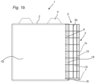
- Fig. 1b shows one of the lateral sides 3b of the lattice 3.
- the edge of the lateral side 3b of the lattice 3 extends into the support block 2.
- One of the wires 6 on the edge on the lateral side 3b of the lattice 3 is arranged along the front side of the support block 2, embedded in the material of the support block 2, at an approximately constant distance from the adjacent surface 18 of the support block 2.
- the lattice 3 also has a bottom side 3c, approximately transversal to both of the main area 3a and the lateral sides 3b.
- the bottom side 3c is angled slightly downwards from the support block 2.
- the outer edge 7 of the bottom side 3c is arranged approximately at the level of the bottom side of the support block 2. Preferably it does not extend below this level, since there is a desire to make the construction blocks 1 completely stackable.
- the lattice 3 of each block 1 must not extend outside of the upper, lower or lateral sides of the support block 2.
- the lateral sides 3b of the lattice 3 do not extend outside of the lateral sides of the support block 2, as seen in Fig. 1c .
- the main area 3a preferably extends in front of the adjacent surface 18 to as large an extent as possible.
- the adjacent surface 18 may only be slightly visible, or even not at all visible, at the outer edges of the construction block 1, when viewed from the front.
- the lateral sides 3b and the bottom side 3c of the lattice 3 are bent to form acute angles to the main area 3a of the lattice 3.
- the edges of the lateral and bottom sides 3b, 3c are arranged within the perimeter of the main area 3a.
- the lateral and bottom sides 3b, 3c are inclined inwards from the outer edges 7 of the main area 3a to the wires 6 at the edges of the lateral and bottom sides 3b, 3c of the lattice 3.
- the wires 6 at the edges of the lateral and bottom sides 3b, 3c of the lattice 3 may be securely anchored in the concrete of the support block 2 at some distance from the lateral and lower sides of the support block 2.
- the upper, longitudinal side 16 of the lattice 3, opposite to the bottom side 3c, is open, such that a loose, solid material may be deposited into the space 5 inside the lattice 3.
- the loose, solid material may be stones, often of a size larger than the mesh size of the lattice 3.
- Other materials may be crushed bricks, glass, or ceramics, etc, in particular if a decorative effect is desired.
- Materials of a small particle size e. g. sand, gravel, or soil, may be deposited inside the lattice 3, if a sheet of material with a small mesh size is used for keeping the small particles from escaping through the larger meshes of the lattice 3.
- a sheet material with a small mesh size may be burlap, and the material of a small particle size therein may be soil. Holes may be cut in the burlap for planting plants that may grow to cover the lattice 3 in part or fully.
- the projections 4 have the shape of cropped pyramids in the embodiment shown in Figs. 1a-1c .
- the corresponding recesses which are not seen in the figures, have a complementary shape.
- the slanting sides 4a of the projections 4, and of the recesses may have a guiding function, when the construction blocks 1 are stacked. Slight misalignments of the projections 4 and the recesses will be compensated by the slanting sides 4a.
- the side edges 4b between two adjacent slanting surfaces 4a may assist in preventing that an upper construction block 1 is rotated relative to a lower construction block 1, whereon it is placed, by a similar type of guiding function.
- Each lateral side 3b of the lattice 3 is provided with a supporting wire 8 which protrudes a short distance outside of the lattice 3 at both its outer ends 8a, 8b, as seen in Fig. 2a .
- These supporting wires 8 have their main function during the manufacture of the construction block 1.
- the lattice 3 may be placed at the top of the mould 9, with the outer ends 8a, 8b of the supporting wire 8 protruding so far that they may be placed on the edges of the mould 9.
- Parts on the outer edge of the lattice 3 may extend into the mould 9, such that the outermost wire 6 in each lateral side 3b and in the bottom side 3c (see Fig. 2b ) of the lattice 3 may be covered by the liquid concrete poured into the mould 9.
- the lattice 3 may hereby be solidly joined with the support block 2, when the concrete has cured.
- FIG. 3 A perspective view of a mould 9 according to an embodiment of the disclosure may be seen in Fig. 3 .
- the mould 9 has the general shape of a rectangular prism wherein two of the sides are profiled for forming the protrusions 4 and recesses of the finished support block 2 as well as bevelled edges, which are present in at least some of the embodiments of the construction block 1.
- the support block 2 it is turned over so that its top and bottom sides, with the protrusions 4 and corresponding recesses, are facing sideways.
- the outer sides of the mould 9 are provided with stiffening ridges 10, to keep the sides of the mould 9 from bulging when it is filled with concrete.
- the lattice 3 has been positioned on the upwardly directed edges of the mould 9.
- the outer ends 8a, 8b of the supporting wires 8 extend outside of the upper opening of the mould 9, such that the lattice 3 may be kept in its position on top of the mould 9, and not fall into it.
- the notches 17 may be sufficient to keep the lattice 3 in its position.
- the outermost wires 6 at the edges of the lateral and bottom sides 3b, 3c of the lattice 3, are arranged at a distance below the supporting wires 8, which keep the lattice 3 in its position on the mould 9.
- the lattice 3 extends into the mould 9 with its lateral and bottom sides 3b, 3c, and its outermost wires 6 are positioned below an intended fill line 11 see Fig. 4 ) for the concrete. They are arranged such that they may be approximately aligned with the surface of the concrete, when the mould 9 has been filled with wet concrete, provided that the mould 9 is positioned on an approximately planar and level surface.
- the outermost wires 6 of the lattice 3 may be embedded in the concrete, and the lattice 3 may be securely fastened to the front side of the support block 2, along the side and bottom edges thereof, and at a sufficient distance therefrom to ensure that loads on the lattice 3 may not break the edges nor the lateral sides 19 of the support block 2.
- Fig. 4 shows, in a different, sectional view, the arrangement of the lattice 3 on the mould 9.
- the fill line 11 is suggested with a dashed line at a position above the outermost wire 6 which is to be embedded in the concrete.
- the fill line 11 is not higher than the upper edge of the mould 9, where the supporting wire 8 is positioned.
- the bottom side 3c is angled in a direction outwards from the centre of the mould 9, which means that it may be angled outwards from the centre of the support block 2.
- the lateral sides 3b may be angled outwards in a similar manner, as discussed above. Very little of the support block 2 may hence be visible in a view from the front of the finished construction block 1, when the filling material has been placed inside the lattice 3.
- Fig. 4 shows that the side of the lattice 3 opposite the bottom side 3c is open. In a position of use, this open side 16 may be directed upwards, so that the loose, solid material may be easily placed inside the lattice 3 at any time after the concrete of the support block 2 has cured.
- these steps of the manufacture of the construction block 1 may be performed separately from one another, in the most practical manner.
- the separation of the steps may be with respect to time or location, or both. Costs for long transports of heavy goods and costs for storing the partially, or completely, finished goods may be reduced.
- Each step of the manufacture may be performed at a time and place which is most efficient, which means that the filling of the material inside the lattice 3 may, e.g., be performed at the construction site, shortly before the construction block 1 is placed in its final position.
- the construction blocks 1 may be provided with further lattices in addition to the lattice 3 which extends into the support block 2 as described above.
- Such further lattices may be fastened on any lateral side or top side of the support block 2. They may be fastened by conventional fastening means, such as screws or bolts.
- Lumps of solid material etc., as described above, may be arranged in a space between the support block 2 and the lattice.
- Various decorative effects may hereby be attained.
- the wires 15 of the lattice 3 may be subjected to deflections, in particular a bulging of the main area 3a of the lattice.
- one or more hooks 12, as seen in Fig. 5 may be arranged between the main area 3a and the support block 2.
- the hooks 12 may be arranged at the time of casting the support block 2, such that the hooks 12 may be anchored in the concrete, in a similar manner to the wires 6 at the edges of the lattice 3.
- Each hook 12 may be arranged to hang by an end portion 14 from the main area 3a of the lattice 3 in at least one place, but preferably in several places.
- one single hook 12 may keep two wires 15 from deflecting in one area of the lattice 3a.
- the distances between the hooks 12 may be decided according to experience. They may also be calculated based on one or more of the following: an expected load on the wires 15, the dimension of the wires 15, the maximally acceptable deflection, the dimensions of the hook 12, the expected embedding of the hook 12 in the concrete as well as the adhesion of the concrete to the hook 12.
- the hooks 12 may be arranged hanging from the wires 15 in the main area 3a of the lattice 3, when the lattice 3 is arranged on the mould 9.
- the hooks 12 extend at least as low as the outermost wires 6 that are to be embedded in the concrete, preferably lower.
- the lower portions 13 of the hooks 12 may be covered.
- the hooks 12 may be fixed in their respective positions, thereby keeping the distance between the adjacent surface 18 of the concrete and the lattice 3.
- the wires 15 of the lattice 3 may be kept from deflecting, even when the space 5 between the support block 2 and the lattice 3 is filled with stones, etc.
Landscapes
- Engineering & Computer Science (AREA)
- Civil Engineering (AREA)
- Structural Engineering (AREA)
- Architecture (AREA)
- Environmental & Geological Engineering (AREA)
- Life Sciences & Earth Sciences (AREA)
- General Life Sciences & Earth Sciences (AREA)
- Mining & Mineral Resources (AREA)
- Paleontology (AREA)
- General Engineering & Computer Science (AREA)
- Manufacturing & Machinery (AREA)
- Chemical & Material Sciences (AREA)
- Ceramic Engineering (AREA)
- Mechanical Engineering (AREA)
- Physics & Mathematics (AREA)
- Electromagnetism (AREA)
- Revetment (AREA)
- Manufacturing Of Tubular Articles Or Embedded Moulded Articles (AREA)
- Sewage (AREA)
- Conveying And Assembling Of Building Elements In Situ (AREA)
Claims (11)
- Bauelement (1) zum Bauen von Wänden, umfassend einen Stützblock (2) aus Beton und ein Gitter (3), das eine Reihe von sich schneidenden Gitterdrähten (15, 8, 6) umfasst, wobei das Gitter (3) mit Seitenflächen (3b, 3c) davon versehen ist, die angeordnet sind, um ein Volumen (5) auf einer Seite des Stützblocks (2) zwischen einer Hauptfläche (3a) des Gitters (3) und einer benachbarten Fläche (18) des Stützblocks (2) einzuschließen, sodass das Volumen (5) mit Brocken aus einem losen, festen Material füllbar ist, und mindestens einer der Drähte (6) innerhalb des Betons angeordnet und an der benachbarten Fläche (18) des Stützblocks (2) ausgerichtet ist, der unter der Fläche (18) positioniert ist, dadurch gekennzeichnet, dass die Seitenflächen (3b, 3c) des Gitters (3) nach innen abgewinkelt sind, wobei sie einen spitzen Winkel mit der Hauptfläche (3a) bilden.
- Bauelement (1) nach Anspruch 1, wobei die Drähte (6), die an der benachbarten Fläche (18) ausgerichtet sind, an einer Kante von jeder der Seitenflächen (3b, 3c) des Gitters (3) angeordnet sind.
- Bauelement (1) nach Anspruch 1 oder Anspruch 2, wobei das Gitter (3) mit einer länglichen Öffnung (16) entlang einer seiner Seitenkanten versehen ist, sodass das eingeschlossene Volumen eine Öffnung zum Füllen des Volumens aufweist.
- Bauelement (1) nach einem der vorhergehenden Ansprüche, wobei der Stützblock (2) eine Reihe von Vorsprüngen (4) und Aussparungen aufweist, die derart angeordnet sind, dass zwei oder mehr der Bauelemente (1) zumindest teilweise miteinander verschachtelbar und relativ zueinander positionierbar sind.
- Bauelement (1) nach einem der vorhergehenden Ansprüche, wobei sich eine Reihe von Haken (12) quer zwischen dem Gitter (3) und dem Stützblock (2) erstreckt, um das Gitter (3) in einem vorbestimmten Abstand zu dem Stützblock (2) zu halten.
- Verfahren zum Herstellen eines Bauelements (1) nach Anspruch 1, die folgenden Schritte umfassend:- Herstellen eines Gitters (3) aus sich schneidenden Gitterdrähten (15, 8, 6);- dauerhaftes Biegen einer oder mehrerer Seitenflächen (3b, 3c) der Gitterdrähte (15), um ein Gitter (3) zu bilden, bei dem sich mindestens eine Seitenfläche (3b, 3c) quer zu einer Hauptfläche (3a) erstreckt;- Füllen einer blockförmigen Form (9) mit nassem Beton bis zu einer Fülllinie (11);- Anordnen des Gitters (3) auf der Form (9), sodass sich ein Raum zwischen dem Gitter (3) und dem Beton bildet;- Aushärtenlassen des Betons zu einem Betonblock (2);- Füllen des Volumens zwischen dem Gitter (3) und dem Beton mit Brocken aus losem, festem Material;wobei die sich quer erstreckenden Seitenflächen des Gitters (3) derart angeordnet sind, dass sie sich in die Form (9) erstrecken, wobei sich ein Draht (6) derart erstreckt, dass er an der Fülllinie (11) ausgerichtet ist und in einem Abstand unter der Fülllinie (11) positioniert ist, und die Seitenflächen (3b, 3c) des Gitters (3) gebogen sind, um spitze Winkel mit der Hauptfläche (3a) zu bilden.
- Verfahren nach Anspruch 6, wobei ein Stützdraht (8) in jeder sich quer erstreckenden Seitenfläche des Gitters (3) aus einem Hohlraum in der Form herausragt, sodass das Gitter (3) an den Seiten der Form (9) gestützt wird, wenn das Gitter (3) darauf angeordnet ist.
- Verfahren nach Anspruch 7, wobei die herausragenden Drahtenden (8a, 8b) des Stützdrahts (8) in Kerben (17) in den Seiten der Form (9) positioniert sind.
- Verfahren nach einem der Ansprüche 6 bis 8, wobei das Gitter (3) und der Betonblock (2) an einer Stelle vorgefertigt werden, die von der Stelle getrennt ist, an der das Volumen zwischen dem Gitter (3) und dem Betonblock (2) gefüllt wird.
- Verfahren nach einem der Ansprüche 6 bis 9, wobei Haken (12) derart angeordnet sind, dass sie in einem Abstand von dem Gitter (3) in die Form (9) unter der Fülllinie (11) herunterhängen, bevor der Beton in der Form (9) zu einem Betonblock (2) aushärtet.
- Verfahren nach einem der Ansprüche 6 bis 10, wobei die Endflächen der Gitterdrähte (15) gebogen werden, bevor das Gitter (3) hergestellt wird.
Applications Claiming Priority (1)
| Application Number | Priority Date | Filing Date | Title |
|---|---|---|---|
| SE2250340A SE546855C2 (en) | 2022-03-18 | 2022-03-18 | Construction component for building walls and method of manufacturing the construction component |
Publications (3)
| Publication Number | Publication Date |
|---|---|
| EP4245938A1 EP4245938A1 (de) | 2023-09-20 |
| EP4245938B1 true EP4245938B1 (de) | 2025-04-30 |
| EP4245938C0 EP4245938C0 (de) | 2025-04-30 |
Family
ID=85703925
Family Applications (1)
| Application Number | Title | Priority Date | Filing Date |
|---|---|---|---|
| EP23162260.6A Active EP4245938B1 (de) | 2022-03-18 | 2023-03-16 | Baublock und herstellungsverfahren |
Country Status (3)
| Country | Link |
|---|---|
| EP (1) | EP4245938B1 (de) |
| PL (1) | PL4245938T3 (de) |
| SE (1) | SE546855C2 (de) |
Family Cites Families (6)
| Publication number | Priority date | Publication date | Assignee | Title |
|---|---|---|---|---|
| US5788424A (en) * | 1996-05-01 | 1998-08-04 | Torch; Joe | Retaining wall units and retaining walls containing the same |
| FR2897375B1 (fr) * | 2006-02-14 | 2008-04-18 | Girard Sopreva Soc Par Actions | Bloc a parement pour construction de murs |
| KR100894654B1 (ko) * | 2008-06-02 | 2009-04-30 | (주)아이엠에스케이 | 전면녹화용 식생 블록 |
| WO2010040225A1 (en) * | 2008-10-08 | 2010-04-15 | Tyler Matys | Facing element and method of fabricating thereof |
| IT201800011171A1 (it) * | 2018-12-17 | 2020-06-17 | Valter Angeli | Modulo prefabbricato per il rivestimento o la realizzazione di pareti con copertura vegetale |
| CZ308763B6 (cs) * | 2019-04-03 | 2021-05-05 | Herkul A.S. | Stavební prvek |
-
2022
- 2022-03-18 SE SE2250340A patent/SE546855C2/en unknown
-
2023
- 2023-03-16 PL PL23162260.6T patent/PL4245938T3/pl unknown
- 2023-03-16 EP EP23162260.6A patent/EP4245938B1/de active Active
Also Published As
| Publication number | Publication date |
|---|---|
| SE546855C2 (en) | 2025-02-25 |
| EP4245938A1 (de) | 2023-09-20 |
| PL4245938T3 (pl) | 2025-06-09 |
| SE2250340A1 (en) | 2023-09-19 |
| EP4245938C0 (de) | 2025-04-30 |
Similar Documents
| Publication | Publication Date | Title |
|---|---|---|
| EP0749511B1 (de) | Element zur herstellung einer bewehrten betonstruktur mit hohlräumen, füllkörper zur herstellung eines solchen elements, und verfahren zur herstellung einer betonstruktur mit hohlräumen | |
| US8523486B2 (en) | Concrete culvert assembly and related methods | |
| US9574317B2 (en) | Wall block and wall block system | |
| US11598094B2 (en) | Retaining wall block and retaining wall block system | |
| US20140241805A1 (en) | Concrete bridge system and related methods | |
| EP0610269A1 (de) | Pflastersystem | |
| FR2570421A1 (fr) | Dispositif et procede de construction pour la realisation d'edifices ou autres devant avoir de bonnes caracteristiques de ductilite | |
| US20090185870A1 (en) | Retaining wall block and method of manufacture | |
| EP4245938A1 (de) | Baublock und herstellungsverfahren | |
| NL1024629C1 (nl) | Bouwelement. | |
| CA2395657C (en) | Method of constructing formwork and an element for casting concrete components | |
| CA1268958A (en) | Screed rails | |
| EP2582503B1 (de) | Form zur herstellung eines matratzenartigen schutz- und befestigungselements | |
| JP4696084B2 (ja) | 擁壁の施工方法、コンクリート製品およびその製造方法 | |
| JP5367052B2 (ja) | 路肩保護ブロック、路肩構造及び現場打ちコンクリート型枠 | |
| JP4920762B2 (ja) | 擁壁の施工方法 | |
| CA2235426A1 (en) | Concrete wall formwork and connectors therefor | |
| KR102087905B1 (ko) | 옹벽용 섬유셀 유닛 및 이를 이용한 조립식 옹벽구조 | |
| NL1016448C2 (nl) | Betonsteen. | |
| NL1025707C2 (nl) | Drijvend funderingselement, samenstel van twee of meer funderingselementen, gebouw geplaatst op een funderingselement alsmede werkwijze voor het vervaardigen van een funderingselement. | |
| WO2005047624A1 (en) | Device for closing off an edge barrier when pouring concrete | |
| JP2001214461A (ja) | 擁 壁 | |
| DK2986780T3 (en) | Concrete bridge system | |
| KR20160053290A (ko) | 생태 교량의 상부 구조 | |
| JPS58101968A (ja) | 基盤型枠の組み立て据付方法 |
Legal Events
| Date | Code | Title | Description |
|---|---|---|---|
| PUAI | Public reference made under article 153(3) epc to a published international application that has entered the european phase |
Free format text: ORIGINAL CODE: 0009012 |
|
| STAA | Information on the status of an ep patent application or granted ep patent |
Free format text: STATUS: THE APPLICATION HAS BEEN PUBLISHED |
|
| AK | Designated contracting states |
Kind code of ref document: A1 Designated state(s): AL AT BE BG CH CY CZ DE DK EE ES FI FR GB GR HR HU IE IS IT LI LT LU LV MC ME MK MT NL NO PL PT RO RS SE SI SK SM TR |
|
| STAA | Information on the status of an ep patent application or granted ep patent |
Free format text: STATUS: REQUEST FOR EXAMINATION WAS MADE |
|
| 17P | Request for examination filed |
Effective date: 20240313 |
|
| RBV | Designated contracting states (corrected) |
Designated state(s): AL AT BE BG CH CY CZ DE DK EE ES FI FR GB GR HR HU IE IS IT LI LT LU LV MC ME MK MT NL NO PL PT RO RS SE SI SK SM TR |
|
| P01 | Opt-out of the competence of the unified patent court (upc) registered |
Free format text: CASE NUMBER: APP_53795/2024 Effective date: 20240927 |
|
| GRAP | Despatch of communication of intention to grant a patent |
Free format text: ORIGINAL CODE: EPIDOSNIGR1 |
|
| STAA | Information on the status of an ep patent application or granted ep patent |
Free format text: STATUS: GRANT OF PATENT IS INTENDED |
|
| RIC1 | Information provided on ipc code assigned before grant |
Ipc: E04F 13/12 20060101ALI20241023BHEP Ipc: E02D 29/02 20060101ALI20241023BHEP Ipc: E02D 17/20 20060101ALI20241023BHEP Ipc: E01F 8/02 20060101ALI20241023BHEP Ipc: E04B 2/08 20060101AFI20241023BHEP |
|
| INTG | Intention to grant announced |
Effective date: 20241122 |
|
| GRAS | Grant fee paid |
Free format text: ORIGINAL CODE: EPIDOSNIGR3 |
|
| GRAA | (expected) grant |
Free format text: ORIGINAL CODE: 0009210 |
|
| STAA | Information on the status of an ep patent application or granted ep patent |
Free format text: STATUS: THE PATENT HAS BEEN GRANTED |
|
| AK | Designated contracting states |
Kind code of ref document: B1 Designated state(s): AL AT BE BG CH CY CZ DE DK EE ES FI FR GB GR HR HU IE IS IT LI LT LU LV MC ME MK MT NL NO PL PT RO RS SE SI SK SM TR |
|
| REG | Reference to a national code |
Ref country code: CH Ref legal event code: EP Ref country code: GB Ref legal event code: FG4D |
|
| REG | Reference to a national code |
Ref country code: DE Ref legal event code: R096 Ref document number: 602023003127 Country of ref document: DE |
|
| REG | Reference to a national code |
Ref country code: IE Ref legal event code: FG4D |
|
| U01 | Request for unitary effect filed |
Effective date: 20250513 |
|
| U07 | Unitary effect registered |
Designated state(s): AT BE BG DE DK EE FI FR IT LT LU LV MT NL PT RO SE SI Effective date: 20250526 |
|
| P04 | Withdrawal of opt-out of the competence of the unified patent court (upc) registered |
Free format text: CASE NUMBER: APP_24361/2025 Effective date: 20250521 |
|
| PG25 | Lapsed in a contracting state [announced via postgrant information from national office to epo] |
Ref country code: ES Free format text: LAPSE BECAUSE OF FAILURE TO SUBMIT A TRANSLATION OF THE DESCRIPTION OR TO PAY THE FEE WITHIN THE PRESCRIBED TIME-LIMIT Effective date: 20250430 |
|
| PG25 | Lapsed in a contracting state [announced via postgrant information from national office to epo] |
Ref country code: GR Free format text: LAPSE BECAUSE OF FAILURE TO SUBMIT A TRANSLATION OF THE DESCRIPTION OR TO PAY THE FEE WITHIN THE PRESCRIBED TIME-LIMIT Effective date: 20250731 |
|
| PG25 | Lapsed in a contracting state [announced via postgrant information from national office to epo] |
Ref country code: HR Free format text: LAPSE BECAUSE OF FAILURE TO SUBMIT A TRANSLATION OF THE DESCRIPTION OR TO PAY THE FEE WITHIN THE PRESCRIBED TIME-LIMIT Effective date: 20250430 |
|
| PG25 | Lapsed in a contracting state [announced via postgrant information from national office to epo] |
Ref country code: RS Free format text: LAPSE BECAUSE OF FAILURE TO SUBMIT A TRANSLATION OF THE DESCRIPTION OR TO PAY THE FEE WITHIN THE PRESCRIBED TIME-LIMIT Effective date: 20250731 |
|
| PG25 | Lapsed in a contracting state [announced via postgrant information from national office to epo] |
Ref country code: IS Free format text: LAPSE BECAUSE OF FAILURE TO SUBMIT A TRANSLATION OF THE DESCRIPTION OR TO PAY THE FEE WITHIN THE PRESCRIBED TIME-LIMIT Effective date: 20250830 |
|
| PG25 | Lapsed in a contracting state [announced via postgrant information from national office to epo] |
Ref country code: SM Free format text: LAPSE BECAUSE OF FAILURE TO SUBMIT A TRANSLATION OF THE DESCRIPTION OR TO PAY THE FEE WITHIN THE PRESCRIBED TIME-LIMIT Effective date: 20250430 |
|
| PG25 | Lapsed in a contracting state [announced via postgrant information from national office to epo] |
Ref country code: CZ Free format text: LAPSE BECAUSE OF FAILURE TO SUBMIT A TRANSLATION OF THE DESCRIPTION OR TO PAY THE FEE WITHIN THE PRESCRIBED TIME-LIMIT Effective date: 20250430 |
|
| PG25 | Lapsed in a contracting state [announced via postgrant information from national office to epo] |
Ref country code: SK Free format text: LAPSE BECAUSE OF FAILURE TO SUBMIT A TRANSLATION OF THE DESCRIPTION OR TO PAY THE FEE WITHIN THE PRESCRIBED TIME-LIMIT Effective date: 20250430 |
|
| PLBE | No opposition filed within time limit |
Free format text: ORIGINAL CODE: 0009261 |
|
| STAA | Information on the status of an ep patent application or granted ep patent |
Free format text: STATUS: NO OPPOSITION FILED WITHIN TIME LIMIT |
|
| REG | Reference to a national code |
Ref country code: CH Ref legal event code: L10 Free format text: ST27 STATUS EVENT CODE: U-0-0-L10-L00 (AS PROVIDED BY THE NATIONAL OFFICE) Effective date: 20260311 |
|
| 26N | No opposition filed |
Effective date: 20260202 |
|
| U20 | Renewal fee for the european patent with unitary effect paid |
Year of fee payment: 4 Effective date: 20260226 |
|
| PGFP | Annual fee paid to national office [announced via postgrant information from national office to epo] |
Ref country code: NO Payment date: 20260226 Year of fee payment: 4 |
|
| PGFP | Annual fee paid to national office [announced via postgrant information from national office to epo] |
Ref country code: PL Payment date: 20260220 Year of fee payment: 4 |