EP4245950A1 - Dispositif de verrouillage de porte monté sur un élément tubulaire - Google Patents
Dispositif de verrouillage de porte monté sur un élément tubulaire Download PDFInfo
- Publication number
- EP4245950A1 EP4245950A1 EP22162703.7A EP22162703A EP4245950A1 EP 4245950 A1 EP4245950 A1 EP 4245950A1 EP 22162703 A EP22162703 A EP 22162703A EP 4245950 A1 EP4245950 A1 EP 4245950A1
- Authority
- EP
- European Patent Office
- Prior art keywords
- bolt
- tubular member
- nut
- elongated rectangular
- rectangular slot
- Prior art date
- Legal status (The legal status is an assumption and is not a legal conclusion. Google has not performed a legal analysis and makes no representation as to the accuracy of the status listed.)
- Granted
Links
Images



Classifications
-
- E—FIXED CONSTRUCTIONS
- E05—LOCKS; KEYS; WINDOW OR DOOR FITTINGS; SAFES
- E05B—LOCKS; ACCESSORIES THEREFOR; HANDCUFFS
- E05B9/00—Lock casings or latch-mechanism casings ; Fastening locks or fasteners or parts thereof to the wing
- E05B9/02—Casings of latch-bolt or deadbolt locks
-
- E—FIXED CONSTRUCTIONS
- E05—LOCKS; KEYS; WINDOW OR DOOR FITTINGS; SAFES
- E05B—LOCKS; ACCESSORIES THEREFOR; HANDCUFFS
- E05B15/00—Other details of locks; Parts for engagement by bolts of fastening devices
- E05B15/02—Striking-plates; Keepers; Bolt staples; Escutcheons
- E05B15/0205—Striking-plates, keepers, staples
-
- E—FIXED CONSTRUCTIONS
- E05—LOCKS; KEYS; WINDOW OR DOOR FITTINGS; SAFES
- E05B—LOCKS; ACCESSORIES THEREFOR; HANDCUFFS
- E05B65/00—Locks or fastenings for special use
- E05B65/0007—Locks or fastenings for special use for gates
-
- E—FIXED CONSTRUCTIONS
- E05—LOCKS; KEYS; WINDOW OR DOOR FITTINGS; SAFES
- E05B—LOCKS; ACCESSORIES THEREFOR; HANDCUFFS
- E05B9/00—Lock casings or latch-mechanism casings ; Fastening locks or fasteners or parts thereof to the wing
- E05B9/08—Fastening locks or fasteners or parts thereof, e.g. the casings of latch-bolt locks or cylinder locks to the wing
Definitions
- the present invention relates to a system comprising a tubular member and a door lock fixture fixed thereto.
- the door lock fixture comprises a faceplate and a fixture body and is mounted with its fixture body through an elongated rectangular slot in a wall portion of the tubular member, with the faceplate of the fixture being configured to engage an outer surface of said wall portion of the tubular member and to be fixed to said wall portion by means two bolts which are applied through an opening in said faceplate.
- the door lock fixture is in particular a mortice lock or a keep for a door lock.
- the word "door” is used in the present specification to embrace all kinds of closure members such as doors, having a full door panel, and gates.
- the door can either be a hinged or a sliding closure member.
- EP 3 153 645 discloses a system comprising a tubular member and a door lock fixture fixed thereto by a top bolt and a bottom bolt, the tubular member having a wall with an elongated rectangular slot therein, the elongated rectangular slot extending in a longitudinal direction and having an top short side and a bottom short side, the door lock fixture comprising a faceplate and a fixture body, the door lock fixture being configured to be mounted with its fixture body through said elongated rectangular slot with the faceplate engaging an outer surface of said wall, the faceplate comprising a top opening through which said top bolt extends and a bottom opening through which said bottom bolt extends.
- EP 3 153 645 further discloses that the fixture body includes moveable (e.g. slideable or pivotable) clamping levers which, when retracted, allow inserting the fixture body through the rectangular elongated slot, and, when extended, engage an inner surface of the tubular member thereby clamping a wall portion of the tubular member between the clamping lever and the faceplate.
- Each clamping lever comprises a threaded opening which, when the clamping levers are extended, axially aligns with a respective one of the top/bottom opening in the faceplate.
- the top/bottom bolt is fastened through a threaded opening in a respective clamping lever.
- a downside of this known system is the positional leeway between the door lock fixture and the tubular member both in the longitudinal direction of the support member and in the width direction of the elongated rectangular slot.
- the system according to the invention is characterised in that the elongated rectangular slot comprises a top notch at the top short side and a bottom notch at the bottom short side, the notches extending away from one another, said top bolt extending at least partially through said top notch and said bottom bolt extending at least partially through said bottom notch, the system further comprising a top nut and a bottom nut for fastening a respective bolt.
- Providing the notches through which the bolts extend cause a desired positioning of the door lock fixture with respect to the support member. More specifically, as each bolt partially extends through a respective notch, both the height (i.e. longitudinal direction) and the width position of the bolts with respect to the support member is fixed. Likewise, since each bolt extends through a respective opening in the faceplate, the height/width position of the faceplate (i.e. the door lock fixture) is fixed with respect to the support member. The leeway possible with the known system is thus avoided.
- each nut is moveably mounted onto the fixture body between a retracted position in which the fixture body can be inserted through said elongated rectangular slot into the tubular member, and an extended position in which the nut at least partially engages an inner surface of said wall to clamp said wall between the faceplate and the nut.
- each bolt can be tightened strongly so that the wall of the tubular member is clamped strongly and reliably between the faceplate and the nut irrespective of the thickness of the wall of the tubular member.
- the nuts are formed as a threaded opening in a support, each support being moveably mounted on the fixture body between a retracted position in which the fixture body can be inserted through said elongated rectangular slot into the tubular member and an extended position in which the nut is axially aligned with a respective one of the top opening and bottom opening.
- the supports may be manually moveable from their retracted position to their extended position or they may be spring biased towards their extended position with a latch being provided for each support to hold its nut in its retracted position.
- the supports may be slideable or pivotable between their retracted position and their extended position.
- Such supports are disclosed in EP 3 153 645 and have various advantages. For example, such supports are suitable for varying wall thicknesses. Moreover, such supports do not hamper the insertion of the fixture body into the tubular member since it is held in its retracted position when the fixture body is inserted into the tubular member.
- a pivotable support is advantageous as the support can simply pivot within the tubular member from its retracted to its extended position until it engages the inner surface of the wall of the tubular member.
- a spring-biased support ensures that the support has only to be released to be brought automatically by the spring into its extended position.
- a corresponding latch can be actuated to release the support. Actuation of the latch can for example be done through the hole for the bolt in the faceplate.
- the door lock fixture may comprise a removable locking element which holds the support in its retracted position.
- the support is released and moves under the action of said spring in the tubular member until it projects behind the inner surface of the wall of the tubular member.
- the bolt can be inserted through said opening in the faceplate in the fixture and can be screwed in the screw threaded hole in the clamping lever to clamp the wall of the tubular member strongly between the faceplate of the fixture and the nut formed in the support.
- the nuts are irrotatably mounted on a support arm, each support arm being slideably mounted on the fixture body between a retracted position in which the fixture body can be inserted through said elongated rectangular slot into the tubular member and an extended position in which the nut is axially aligned with a respective one of the top opening and bottom opening, each nut being slideably mounted on a respective support arm along a transverse direction which is substantially perpendicular to the longitudinal direction and is preferably further perpendicular to the faceplate.
- This alternative embodiment is also suited for varying wall thicknesses. Furthermore, by having a separate nut and support, the risk of damaging the support is reduced when tensioning the bolt when compared to the first alternative embodiment where the nut is formed as an opening in the support.
- each bolt has a bolt head and a threaded part extending in a first direction, the bolt head defining a hypothetical circumscribed cylinder extending in said first direction, wherein a part of said wall adjacent said notches is located inside a respective hypothetical cylinder.
- a part of the tubular member is located directly underneath the bolt head.
- the tubular support is partially positioned directly between the bolt head and the nut which optimizes force transfer between the door lock fixture and the tubular member.
- each notch comprises a substantially semi-circular part, said part in particular having a diameter between 5 mm and 10 mm and more particularly between 6 mm and 7 mm.
- a leeway between each notch and its respective bolt is at most 1 mm, particularly at most 0,5 mm.
- each notch has an opening width which is measured along a line contiguous with its respective short side, the opening width being at most 50%, particularly at most 40%, and more particularly at most 30%, of a width of the elongated rectangular slot.
- the elongated rectangular slot has a width and a height, the height being at least 4 times, particularly at least 6 times, and more particularly at least 7 times, larger than the width, the width preferably being between 10 and 35 mm, particularly between 15 and 30 mm, and more particularly between 20 and 25 mm.
- the various dimensions of the elongated rectangular slot are mainly determined in view of the dimensions of the lock fixture. Furthermore, the notch dimensions are mainly determined depending on the bolt diameter with higher diameter bolts typically leading to a stronger, albeit more expensive, connection.
- the notches are aligned with one another in the longitudinal direction. This leads to a symmetric design which reduces manufacturing and/or assembly errors.
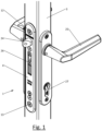
- the present invention generally relates to a system comprising a tubular member 3 and a door lock fixture mounted thereon.
- the door lock fixture is a mortice lock 1 to be inserted into a closure member, in particular in a hollow tubular member 3 thereof.
- the door lock fixture is a morticed lock keep 2 which comprises a body portion that is inserted in the support onto which it is mounted.
- the support is generally formed by a hollow tubular member 3 and can either be a fixed post or a leaf of a double door or gate.
- the door lock fixture (i.e. the mortice lock 1 or the morticed lock keep 2) comprises a faceplate 4 and a fixture body 5.
- the tubular member 3 is generally part of a gate, as illustrated in the figures, or of a door or any other type of hinged closure member and generally comprises a rectangular elongated slot 6 in a wall portion 7.
- the rectangular elongated slot 6 has a top short side 8, a bottom short side 9, and two long sides 10 which extend in a longitudinal direction 11 (which is also the direction along which the tubular body 3 extends).
- the fixture body 5 is designed to be inserted through the rectangular elongated slot 6 with the faceplate 4 engaging an outer side of the wall portion 7.
- a top bolt 12 and a bottom bolt 13 which are placed through a corresponding top/bottom opening in the faceplate 4.
- Each bolt 12, 13 further at least partially extends through a corresponding one of a top notch 14 and a bottom notch 15 which are provided in a respective top/bottom short side 8, 9. This ensure that the faceplate 4 (and thus the door lock fixture) are correctly aligned with the rectangular elongated slot 6.
- Each bolt 12, 13 is bolted into a corresponding one of a top nut 16 and a bottom nut 17.
- the nuts 16, 17 are located inside the tubular member 3.
- the bolts may fully extend through the tubular member with the nuts being provided on the rear side thereof.
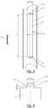
- the elongated rectangular slot 6 has a width W and a height H.
- the height H is at least 4 times, particularly at least 6 times, and more particularly at least 7 times, larger than the width W.
- the width is between 10 and 35 mm, particularly between 15 and 30 mm, and more particularly between 20 and 25 mm, with the width W being about 22 mm in the illustrated embodiment. These dimensions are mainly determined in view of the dimensions of the lock body.
- each notch 14, 15 comprises a semi-circular part 20 and two straight parts 21.
- the semi-circular part 20 in particular having a diameter between 5 mm and 10 mm and more particularly between 6 mm and 7 mm. These dimension of this semi-circular part 20 is mainly determined depending on the bolt diameter and a maximum leeway between the bolt diameter and the semi-circular part 20 is 1 mm and particularly 0,5 mm.
- the two straight parts 21 in the illustrated embodiment each have a length L of 2 mm, but other lengths are possible. The main reason for these straight parts 21 is to avoid the bolts 12, 13 centre-lines to coincide with the top/bottom short side 8, 9. In view of manufacturing tolerances, this could lead to bolts 12, 13 not being correctly positioned in their respective notch 14, 15.
- Each notch 14, 15 has an opening width W o which measured along a line contiguous with its respective short side 8, 9.
- the opening width W o is at most 50%, particularly at most 40%, and more particularly at most 30%, of a width W of the elongated rectangular slot 6. This dimension is mainly determined depending on the bolt diameter and is preferably equal to the diameter of the semi-circular part 20.
- the notches 14, 15 are aligned in the longitudinal direction 11 leading to a symmetric design.
- FIG. 5 illustrates a double wing gate having a mortice lock 1 in a tubular member of a first gate wing 22 and a morticed lock keep 2 in a tubular member of a second gate wing 23.
- the second gate wing may also be a fixed support.
- the lock 1 may have a locking mechanism of any type and comprises a faceplate 4 and a lock body 5.
- the lock 1 may comprise a latch bolt 24 which is operated by means of handles 25, a deadbolt 26 which is operated by means of a key in particular through the intermediary of a lock cylinder 27 (for example a single-barrel euro-profile cylinder), or it may comprise a combination of a latch bolt 24 and a deadbolt 26 as in the embodiments illustrated in the drawings.
- the latch bolt 24 and the deadbolt 26 are slideably mounted in the lock 1 to slide between a retracted and an extended position.
- the deadbolt 26 is however hook-shaped and pivots in the lock 1 between its extended and its retracted positions.
- the lock illustrated in figure 6 is in particular a lock as disclosed in EP 2 186 974 and EP 3 153 645 and further details about this lock can be found therein.
- the morticed lock keep 2 comprises a faceplate 4 and a partially hollow body 5.
- the faceplate 4 comprises an elongated opening 28 and the partially hollow body 5 forms a corresponding elongated slot 29 in which the latch bolt 24 and/or the deadbolt 26 are received as shown in figure 6 .
- the morticed lock keep 2 illustrated in the figures is in particular a morticed lock keep as disclosed in EP 3 153 645 and further details about this morticed lock keep can be found therein.
- the fixture body 5 of the morticed lock keep 2 is provided with two support arms 30 which are (manually) slideably mounted onto the fixture body 5 along the longitudinal direction 11 between a retracted position in which the fixture body 5 can be inserted through the rectangular elongated slot 6 into the tubular member 3 and an extended position (shown in figures 6 and 7 ).
- Each nut 16, 17 comprises a threaded opening configured to receive a bolt 12, 13 used to mount the morticed lock keep 10 on the tubular member 3.
- the nut 16, 17 is irrotatable with respect to the support arm 30 due to its square (in general non-circular) outer shape.
- the fixture body 5 of the mortice lock 1 is provided with two supports 32 that are moveable (e.g. slideable or pivotable) between a retracted position in which the fixture body 5 can be inserted into the elongated opening 6 and an extended position in which each support 32 engages an inner surface of the tubular member 3.
- Each support 32 is provided with a threaded opening which forms a respective one of the nuts 16, 17.
- the supports 32 are pivotable and spring-biased due to a spring member 33 and latches 34 are provided to maintain the supports 32 in their retracted position.
- the supports 32 are identical to those described in EP 3 153 645 A1 which is incorporated herein by reference.
- each bolt has a bolt head and a threaded part extending in direction 31.
- the bolt head defines a hypothetical circumscribed cylinder extending in direction 31, wherein a part of said wall 7 adjacent said notches 14, 15 is located inside a respective hypothetical cylinder.
- fixation systems described above for the mortice lock 1 and the morticed lock keep 2 are interchangeable and still others may be used in accordance with the present invention related to the provision of notches 14, 15 for the alignment of the fixation bolts 12, 13.
Landscapes
- Engineering & Computer Science (AREA)
- Mechanical Engineering (AREA)
- Clamps And Clips (AREA)
- Control Of Vending Devices And Auxiliary Devices For Vending Devices (AREA)
Priority Applications (2)
| Application Number | Priority Date | Filing Date | Title |
|---|---|---|---|
| EP22162703.7A EP4245950B1 (fr) | 2022-03-17 | 2022-03-17 | Dispositif de verrouillage de porte monté sur un élément tubulaire |
| PL22162703.7T PL4245950T3 (pl) | 2022-03-17 | 2022-03-17 | Osprzęt ryglujący drzwi zamontowany na członie rurowym |
Applications Claiming Priority (1)
| Application Number | Priority Date | Filing Date | Title |
|---|---|---|---|
| EP22162703.7A EP4245950B1 (fr) | 2022-03-17 | 2022-03-17 | Dispositif de verrouillage de porte monté sur un élément tubulaire |
Publications (3)
| Publication Number | Publication Date |
|---|---|
| EP4245950A1 true EP4245950A1 (fr) | 2023-09-20 |
| EP4245950C0 EP4245950C0 (fr) | 2025-01-22 |
| EP4245950B1 EP4245950B1 (fr) | 2025-01-22 |
Family
ID=80787194
Family Applications (1)
| Application Number | Title | Priority Date | Filing Date |
|---|---|---|---|
| EP22162703.7A Active EP4245950B1 (fr) | 2022-03-17 | 2022-03-17 | Dispositif de verrouillage de porte monté sur un élément tubulaire |
Country Status (2)
| Country | Link |
|---|---|
| EP (1) | EP4245950B1 (fr) |
| PL (1) | PL4245950T3 (fr) |
Cited By (3)
| Publication number | Priority date | Publication date | Assignee | Title |
|---|---|---|---|---|
| EP4567231A1 (fr) | 2023-12-04 | 2025-06-11 | Locinox | Maintien de boulon morcelé et système de fermeture le comprenant |
| EP4567230A1 (fr) | 2023-12-04 | 2025-06-11 | Locinox | Maintien de boulon morcelé et système de fermeture le comprenant |
| EP4715145A1 (fr) | 2024-09-18 | 2026-03-25 | Locinox | Serrure pour un élément de fermeture articulé |
Citations (3)
| Publication number | Priority date | Publication date | Assignee | Title |
|---|---|---|---|---|
| DE20022248U1 (de) * | 2000-12-13 | 2001-05-17 | BOS GmbH, 48282 Emsdetten | Fallenverstelleinheit |
| EP2186974A1 (fr) | 2008-11-14 | 2010-05-19 | Joseph Talpe | Verrou de cylindre avec boulon assemblé en pivot |
| EP3153645A1 (fr) | 2015-10-06 | 2017-04-12 | Locinox | Dispositif de verrouillage de porte conçu pour être monté sur un élément tubulaire |
Family Cites Families (1)
| Publication number | Priority date | Publication date | Assignee | Title |
|---|---|---|---|---|
| PL4159962T3 (pl) * | 2021-10-01 | 2025-03-24 | Locinox | Brama dwuskrzydłowa i sposób jej wytwarzania |
-
2022
- 2022-03-17 PL PL22162703.7T patent/PL4245950T3/pl unknown
- 2022-03-17 EP EP22162703.7A patent/EP4245950B1/fr active Active
Patent Citations (3)
| Publication number | Priority date | Publication date | Assignee | Title |
|---|---|---|---|---|
| DE20022248U1 (de) * | 2000-12-13 | 2001-05-17 | BOS GmbH, 48282 Emsdetten | Fallenverstelleinheit |
| EP2186974A1 (fr) | 2008-11-14 | 2010-05-19 | Joseph Talpe | Verrou de cylindre avec boulon assemblé en pivot |
| EP3153645A1 (fr) | 2015-10-06 | 2017-04-12 | Locinox | Dispositif de verrouillage de porte conçu pour être monté sur un élément tubulaire |
Cited By (4)
| Publication number | Priority date | Publication date | Assignee | Title |
|---|---|---|---|---|
| EP4567231A1 (fr) | 2023-12-04 | 2025-06-11 | Locinox | Maintien de boulon morcelé et système de fermeture le comprenant |
| EP4567230A1 (fr) | 2023-12-04 | 2025-06-11 | Locinox | Maintien de boulon morcelé et système de fermeture le comprenant |
| EP4567232A1 (fr) | 2023-12-04 | 2025-06-11 | Locinox | Maintien de boulon morcelé et système de fermeture le comprenant |
| EP4715145A1 (fr) | 2024-09-18 | 2026-03-25 | Locinox | Serrure pour un élément de fermeture articulé |
Also Published As
| Publication number | Publication date |
|---|---|
| EP4245950C0 (fr) | 2025-01-22 |
| PL4245950T3 (pl) | 2025-03-31 |
| EP4245950B1 (fr) | 2025-01-22 |
Similar Documents
| Publication | Publication Date | Title |
|---|---|---|
| EP4245950A1 (fr) | Dispositif de verrouillage de porte monté sur un élément tubulaire | |
| EP4245951B1 (fr) | Dispositif de verrouillage de porte agencé pour être monté sur un élément tubulaire | |
| US6502435B2 (en) | Locks | |
| EP3153645B1 (fr) | Dispositif de verrouillage de porte conçu pour être monté sur un élément tubulaire | |
| CA2364823C (fr) | Fenetre a battants avec guide de ferrure et butee | |
| US7707862B2 (en) | Multi-point door lock and offset extension bolt assembly | |
| WO2010001170A2 (fr) | Ensemble de plaques de façade pour poignées de porte | |
| US5489128A (en) | Lockset having adjustable backset | |
| NO160535B (no) | Festeanordninger for glidedoerer og -vinduer. | |
| US5730478A (en) | Method and apparatus for mounting a push/pull handle on a latch | |
| MX2007006923A (es) | Metodo para montar un mecanismo de accionamiento para marcos de puertas y ventanas. | |
| US20190301204A1 (en) | Barn door handle assembly, strike assembly, and lock system | |
| US5040393A (en) | Door lock module | |
| WO2008003977A1 (fr) | Ensemble de plaquettes pour loquet de porte | |
| US7207608B2 (en) | System, method and apparatus for an adjustable door striker | |
| AU2009311262B2 (en) | A multipoint lock assembly | |
| HK1044180A1 (en) | Adjustable deadbolt and method of adjusting thereof | |
| US7533551B1 (en) | Door lock with key cylinder | |
| US6305886B1 (en) | Drill guide fixture for drilling, to open, disc padlocks, rectangular padlocks, door knobs and lever locks | |
| DE4012253C1 (en) | Control magnet carrier - has U=shaped bin with bridge port having attachment for fixing to lock plate and two shanks | |
| US20060156768A1 (en) | Method and apparatus for locking a container | |
| US20040205936A1 (en) | Escutcheon plate assembly | |
| US4682482A (en) | Deadbolt lock | |
| GB2211882A (en) | Improvements in or relating to fasteners | |
| US20200032562A1 (en) | Lock assembly |
Legal Events
| Date | Code | Title | Description |
|---|---|---|---|
| PUAI | Public reference made under article 153(3) epc to a published international application that has entered the european phase |
Free format text: ORIGINAL CODE: 0009012 |
|
| STAA | Information on the status of an ep patent application or granted ep patent |
Free format text: STATUS: THE APPLICATION HAS BEEN PUBLISHED |
|
| AK | Designated contracting states |
Kind code of ref document: A1 Designated state(s): AL AT BE BG CH CY CZ DE DK EE ES FI FR GB GR HR HU IE IS IT LI LT LU LV MC MK MT NL NO PL PT RO RS SE SI SK SM TR |
|
| STAA | Information on the status of an ep patent application or granted ep patent |
Free format text: STATUS: REQUEST FOR EXAMINATION WAS MADE |
|
| 17P | Request for examination filed |
Effective date: 20240315 |
|
| RBV | Designated contracting states (corrected) |
Designated state(s): AL AT BE BG CH CY CZ DE DK EE ES FI FR GB GR HR HU IE IS IT LI LT LU LV MC MK MT NL NO PL PT RO RS SE SI SK SM TR |
|
| STAA | Information on the status of an ep patent application or granted ep patent |
Free format text: STATUS: EXAMINATION IS IN PROGRESS |
|
| 17Q | First examination report despatched |
Effective date: 20240801 |
|
| GRAP | Despatch of communication of intention to grant a patent |
Free format text: ORIGINAL CODE: EPIDOSNIGR1 |
|
| STAA | Information on the status of an ep patent application or granted ep patent |
Free format text: STATUS: GRANT OF PATENT IS INTENDED |
|
| INTG | Intention to grant announced |
Effective date: 20241011 |
|
| GRAS | Grant fee paid |
Free format text: ORIGINAL CODE: EPIDOSNIGR3 |
|
| GRAA | (expected) grant |
Free format text: ORIGINAL CODE: 0009210 |
|
| STAA | Information on the status of an ep patent application or granted ep patent |
Free format text: STATUS: THE PATENT HAS BEEN GRANTED |
|
| AK | Designated contracting states |
Kind code of ref document: B1 Designated state(s): AL AT BE BG CH CY CZ DE DK EE ES FI FR GB GR HR HU IE IS IT LI LT LU LV MC MK MT NL NO PL PT RO RS SE SI SK SM TR |
|
| REG | Reference to a national code |
Ref country code: GB Ref legal event code: FG4D |
|
| REG | Reference to a national code |
Ref country code: CH Ref legal event code: EP |
|
| REG | Reference to a national code |
Ref country code: IE Ref legal event code: FG4D |
|
| REG | Reference to a national code |
Ref country code: DE Ref legal event code: R096 Ref document number: 602022009698 Country of ref document: DE |
|
| U01 | Request for unitary effect filed |
Effective date: 20250213 |
|
| U07 | Unitary effect registered |
Designated state(s): AT BE BG DE DK EE FI FR IT LT LU LV MT NL PT RO SE SI Effective date: 20250219 |
|
| U20 | Renewal fee for the european patent with unitary effect paid |
Year of fee payment: 4 Effective date: 20250311 |
|
| PG25 | Lapsed in a contracting state [announced via postgrant information from national office to epo] |
Ref country code: RS Free format text: LAPSE BECAUSE OF FAILURE TO SUBMIT A TRANSLATION OF THE DESCRIPTION OR TO PAY THE FEE WITHIN THE PRESCRIBED TIME-LIMIT Effective date: 20250422 |
|
| PG25 | Lapsed in a contracting state [announced via postgrant information from national office to epo] |
Ref country code: ES Free format text: LAPSE BECAUSE OF FAILURE TO SUBMIT A TRANSLATION OF THE DESCRIPTION OR TO PAY THE FEE WITHIN THE PRESCRIBED TIME-LIMIT Effective date: 20250122 |
|
| PG25 | Lapsed in a contracting state [announced via postgrant information from national office to epo] |
Ref country code: IS Free format text: LAPSE BECAUSE OF FAILURE TO SUBMIT A TRANSLATION OF THE DESCRIPTION OR TO PAY THE FEE WITHIN THE PRESCRIBED TIME-LIMIT Effective date: 20250522 Ref country code: NO Free format text: LAPSE BECAUSE OF FAILURE TO SUBMIT A TRANSLATION OF THE DESCRIPTION OR TO PAY THE FEE WITHIN THE PRESCRIBED TIME-LIMIT Effective date: 20250422 |
|
| PG25 | Lapsed in a contracting state [announced via postgrant information from national office to epo] |
Ref country code: HR Free format text: LAPSE BECAUSE OF FAILURE TO SUBMIT A TRANSLATION OF THE DESCRIPTION OR TO PAY THE FEE WITHIN THE PRESCRIBED TIME-LIMIT Effective date: 20250122 |
|
| PG25 | Lapsed in a contracting state [announced via postgrant information from national office to epo] |
Ref country code: GR Free format text: LAPSE BECAUSE OF FAILURE TO SUBMIT A TRANSLATION OF THE DESCRIPTION OR TO PAY THE FEE WITHIN THE PRESCRIBED TIME-LIMIT Effective date: 20250423 |
|
| PG25 | Lapsed in a contracting state [announced via postgrant information from national office to epo] |
Ref country code: SM Free format text: LAPSE BECAUSE OF FAILURE TO SUBMIT A TRANSLATION OF THE DESCRIPTION OR TO PAY THE FEE WITHIN THE PRESCRIBED TIME-LIMIT Effective date: 20250122 |
|
| PG25 | Lapsed in a contracting state [announced via postgrant information from national office to epo] |
Ref country code: MC Free format text: LAPSE BECAUSE OF FAILURE TO SUBMIT A TRANSLATION OF THE DESCRIPTION OR TO PAY THE FEE WITHIN THE PRESCRIBED TIME-LIMIT Effective date: 20250122 |
|
| PG25 | Lapsed in a contracting state [announced via postgrant information from national office to epo] |
Ref country code: CZ Free format text: LAPSE BECAUSE OF FAILURE TO SUBMIT A TRANSLATION OF THE DESCRIPTION OR TO PAY THE FEE WITHIN THE PRESCRIBED TIME-LIMIT Effective date: 20250122 |
|
| REG | Reference to a national code |
Ref country code: CH Ref legal event code: H13 Free format text: ST27 STATUS EVENT CODE: U-0-0-H10-H13 (AS PROVIDED BY THE NATIONAL OFFICE) Effective date: 20251023 |
|
| PG25 | Lapsed in a contracting state [announced via postgrant information from national office to epo] |
Ref country code: SK Free format text: LAPSE BECAUSE OF FAILURE TO SUBMIT A TRANSLATION OF THE DESCRIPTION OR TO PAY THE FEE WITHIN THE PRESCRIBED TIME-LIMIT Effective date: 20250122 |
|
| PLBE | No opposition filed within time limit |
Free format text: ORIGINAL CODE: 0009261 |
|
| STAA | Information on the status of an ep patent application or granted ep patent |
Free format text: STATUS: NO OPPOSITION FILED WITHIN TIME LIMIT |
|
| 26N | No opposition filed |
Effective date: 20251023 |
|
| PG25 | Lapsed in a contracting state [announced via postgrant information from national office to epo] |
Ref country code: CH Free format text: LAPSE BECAUSE OF NON-PAYMENT OF DUE FEES Effective date: 20250331 |
|
| PG25 | Lapsed in a contracting state [announced via postgrant information from national office to epo] |
Ref country code: IE Free format text: LAPSE BECAUSE OF NON-PAYMENT OF DUE FEES Effective date: 20250317 |
|
| U20 | Renewal fee for the european patent with unitary effect paid |
Year of fee payment: 5 Effective date: 20260218 |
|
| PGFP | Annual fee paid to national office [announced via postgrant information from national office to epo] |
Ref country code: GB Payment date: 20260304 Year of fee payment: 5 |
|
| PGFP | Annual fee paid to national office [announced via postgrant information from national office to epo] |
Ref country code: PL Payment date: 20260223 Year of fee payment: 5 |