EP4246007B1 - Kegelkupplung und getriebe - Google Patents
Kegelkupplung und getriebe Download PDFInfo
- Publication number
- EP4246007B1 EP4246007B1 EP21950404.0A EP21950404A EP4246007B1 EP 4246007 B1 EP4246007 B1 EP 4246007B1 EP 21950404 A EP21950404 A EP 21950404A EP 4246007 B1 EP4246007 B1 EP 4246007B1
- Authority
- EP
- European Patent Office
- Prior art keywords
- ring
- cone
- outer ring
- nut
- gear
- Prior art date
- Legal status (The legal status is an assumption and is not a legal conclusion. Google has not performed a legal analysis and makes no representation as to the accuracy of the status listed.)
- Active
Links
Images



Classifications
-
- F—MECHANICAL ENGINEERING; LIGHTING; HEATING; WEAPONS; BLASTING
- F16—ENGINEERING ELEMENTS AND UNITS; GENERAL MEASURES FOR PRODUCING AND MAINTAINING EFFECTIVE FUNCTIONING OF MACHINES OR INSTALLATIONS; THERMAL INSULATION IN GENERAL
- F16D—COUPLINGS FOR TRANSMITTING ROTATION; CLUTCHES; BRAKES
- F16D21/00—Systems comprising a plurality of actuated clutches
- F16D21/02—Systems comprising a plurality of actuated clutches for interconnecting three or more shafts or other transmission members in different ways
- F16D21/04—Systems comprising a plurality of actuated clutches for interconnecting three or more shafts or other transmission members in different ways with a shaft carrying a number of rotatable transmission members, e.g. gears, each of which can be connected to the shaft by a clutching member or members between the shaft and the hub of the transmission member
-
- F—MECHANICAL ENGINEERING; LIGHTING; HEATING; WEAPONS; BLASTING
- F16—ENGINEERING ELEMENTS AND UNITS; GENERAL MEASURES FOR PRODUCING AND MAINTAINING EFFECTIVE FUNCTIONING OF MACHINES OR INSTALLATIONS; THERMAL INSULATION IN GENERAL
- F16D—COUPLINGS FOR TRANSMITTING ROTATION; CLUTCHES; BRAKES
- F16D13/00—Friction clutches
- F16D13/22—Friction clutches with axially-movable clutching members
- F16D13/24—Friction clutches with axially-movable clutching members with conical friction surfaces cone clutches
-
- F—MECHANICAL ENGINEERING; LIGHTING; HEATING; WEAPONS; BLASTING
- F16—ENGINEERING ELEMENTS AND UNITS; GENERAL MEASURES FOR PRODUCING AND MAINTAINING EFFECTIVE FUNCTIONING OF MACHINES OR INSTALLATIONS; THERMAL INSULATION IN GENERAL
- F16D—COUPLINGS FOR TRANSMITTING ROTATION; CLUTCHES; BRAKES
- F16D13/00—Friction clutches
- F16D13/22—Friction clutches with axially-movable clutching members
- F16D13/24—Friction clutches with axially-movable clutching members with conical friction surfaces cone clutches
- F16D13/32—Friction clutches with axially-movable clutching members with conical friction surfaces cone clutches in which two or more axially-movable members are pressed from one side towards an axially-located member
-
- F—MECHANICAL ENGINEERING; LIGHTING; HEATING; WEAPONS; BLASTING
- F16—ENGINEERING ELEMENTS AND UNITS; GENERAL MEASURES FOR PRODUCING AND MAINTAINING EFFECTIVE FUNCTIONING OF MACHINES OR INSTALLATIONS; THERMAL INSULATION IN GENERAL
- F16D—COUPLINGS FOR TRANSMITTING ROTATION; CLUTCHES; BRAKES
- F16D23/00—Details of mechanically-actuated clutches not specific for one distinct type
- F16D23/02—Arrangements for synchronisation, also for power-operated clutches
- F16D23/04—Arrangements for synchronisation, also for power-operated clutches with an additional friction clutch
-
- F—MECHANICAL ENGINEERING; LIGHTING; HEATING; WEAPONS; BLASTING
- F16—ENGINEERING ELEMENTS AND UNITS; GENERAL MEASURES FOR PRODUCING AND MAINTAINING EFFECTIVE FUNCTIONING OF MACHINES OR INSTALLATIONS; THERMAL INSULATION IN GENERAL
- F16D—COUPLINGS FOR TRANSMITTING ROTATION; CLUTCHES; BRAKES
- F16D23/00—Details of mechanically-actuated clutches not specific for one distinct type
- F16D23/12—Mechanical clutch-actuating mechanisms arranged outside the clutch as such
-
- F—MECHANICAL ENGINEERING; LIGHTING; HEATING; WEAPONS; BLASTING
- F16—ENGINEERING ELEMENTS AND UNITS; GENERAL MEASURES FOR PRODUCING AND MAINTAINING EFFECTIVE FUNCTIONING OF MACHINES OR INSTALLATIONS; THERMAL INSULATION IN GENERAL
- F16D—COUPLINGS FOR TRANSMITTING ROTATION; CLUTCHES; BRAKES
- F16D23/00—Details of mechanically-actuated clutches not specific for one distinct type
- F16D23/02—Arrangements for synchronisation, also for power-operated clutches
- F16D23/04—Arrangements for synchronisation, also for power-operated clutches with an additional friction clutch
- F16D23/06—Arrangements for synchronisation, also for power-operated clutches with an additional friction clutch and a blocking mechanism preventing the engagement of the main clutch prior to synchronisation
- F16D2023/0681—Double cone synchromesh clutches
-
- F—MECHANICAL ENGINEERING; LIGHTING; HEATING; WEAPONS; BLASTING
- F16—ENGINEERING ELEMENTS AND UNITS; GENERAL MEASURES FOR PRODUCING AND MAINTAINING EFFECTIVE FUNCTIONING OF MACHINES OR INSTALLATIONS; THERMAL INSULATION IN GENERAL
- F16D—COUPLINGS FOR TRANSMITTING ROTATION; CLUTCHES; BRAKES
- F16D23/00—Details of mechanically-actuated clutches not specific for one distinct type
- F16D23/12—Mechanical clutch-actuating mechanisms arranged outside the clutch as such
- F16D2023/123—Clutch actuation by cams, ramps or ball-screw mechanisms
-
- F—MECHANICAL ENGINEERING; LIGHTING; HEATING; WEAPONS; BLASTING
- F16—ENGINEERING ELEMENTS AND UNITS; GENERAL MEASURES FOR PRODUCING AND MAINTAINING EFFECTIVE FUNCTIONING OF MACHINES OR INSTALLATIONS; THERMAL INSULATION IN GENERAL
- F16D—COUPLINGS FOR TRANSMITTING ROTATION; CLUTCHES; BRAKES
- F16D28/00—Electrically-actuated clutches
Definitions
- the present invention relates to the field of vehicle transmissions, and more particularly, to a cone clutch and a transmission.
- a conventional multi-speed transmission need a clutch, a brake, or a synchronizers to shift, and these traditional transmission components are all required to be controlled by means of complex actuators.
- a conventional clutch actuator has an electro-hydraulic controlled hydraulic cylinder and a motor-controlled drum shift fork mechanism.
- 102018111248A1 discloses a synchronous clutch for coupling an auxiliary unit to an internal combustion engine including a first coupling component and a second coupling component, which can be coupled to one another via two friction ring sets.
- US Patent Publication No. 2012/217115A1 discloses a ring of a synchronizing device of a vehicle transmission including a friction surface that interacts with a friction surface of another ring of the synchronizing device and at least one slide surface configured to slidably seat on an abutment surface of the synchronizing device.
- 2008/017470A1 discloses a synchronization device for a change speed gear, including at least one cone clutch which comprises a double cone ring freely rotatable relative to a hub between an inner friction ring and an outer synchronizing ring.
- EP Patent Application No. 02291490.7 discloses a gearbox with parallel shafts comprising a primary shaft and at least one secondary shaft supporting several fixed teeth and several idle gears which mesh with the latter and which can be linked in rotation with their shaft by means of coupling when engaging a gear.
- the electro-hydraulic proportional-controlled hydraulic oil cylinder can accurately control a torque of the clutch or a torque of the brake to enable a driving torque of a vehicle to be not interrupted during the shifting, and thus the shifting is smooth.
- this type of hydraulic actuator it is necessary for this type of hydraulic actuator to be supplied with an actuating force by a hydraulic pump, a proportional pressure solenoid valve, a valve plate, and a hydraulic oil cylinder.
- these parts have high cost and great power consumption, and are thus more suitable for a case where a common oil pump is shared by a plurality of clutches. For an electric vehicle transmission with only one or two clutches or brakes, such a hydraulic actuator is less suitable due to the cost and power consumption of the hydraulic pump.
- the motor-controlled drum shift fork mechanism is realized by using a control motor, a drum, a shift fork, and a synchronizer, and has cost and power consumption lower than the hydraulic actuator.
- the motor-controlled drum shift fork mechanism has power interruption during its shifting, and thus has poor shifting smoothness. Therefore, how to reduce cost and energy consumption of a shift mechanism of the electric vehicle transmission and ensure the shifting smoothness is an urgent technical problem to be solved.
- FIG. 1 is a cross-sectional view of a cone clutch 50 according to an embodiment of the present invention.
- the cone clutch 50 includes a middle cone ring 53, an inner cone ring 52, and an outer ring 61.
- the middle cone ring 53 has an inner ring surface and an outer ring surface, and each of the inner ring surface and the outer ring surface is a conical surface.
- the inner cone ring 52 is disposed on an inner side the middle cone ring 53 and has an outer ring surface.
- the outer ring surface of the inner cone ring 52 is a conical surface matching with the inner ring surface of the middle cone ring 53.
- the outer ring 61 has a conical ring surface matching with the outer ring surface of the middle cone ring 53.
- the outer ring 61 is movable relative to the inner cone ring 52 in an axial direction of the conical ring surface.
- the middle cone ring 53 and the outer ring 61 are connected to two to-be-engaged members, respectively.
- the cone clutch 50 is configured to engage the two to-be-engaged members by forming friction pairs in close contact between the outer ring 61 and the middle cone ring 53 and between the middle cone ring 53 and the inner cone ring 52 when the outer ring is subject to a thrust for urging the outer ring 61 towards the middle cone ring 53.
- the two to-be-engaged members are a shaft and a gear on the shaft.
- the clutch with the friction pairs having two conical ring surfaces is constructed by the middle cone ring 53, the inner cone ring 52, and the outer ring 61.
- the outer ring 61 By controlling the axial movement of the outer ring 61, it is possible to control engagement and disengagement of the cone clutch 50, thereby engaging or disengaging the to-be-engaged member.
- the arrangement of two sets of friction pairs with the conical ring surfaces can reduce the control force of the clutch and enhance the torque capability of the clutch.
- the cone clutch 50 according to the embodiments is particularly suitable for a transmission with less gears and small-and-medium power.
- cone angles of the middle cone ring 53, the inner cone ring 52, and the outer ring 61 may be reasonably set to better amplify an axial force of the clutch.
- an axial force of 3 kN may generate a friction torque of 300 Nm.
- the cone clutch 50 further includes a reset spring 55.
- An end of the reset ring 55 is fixed, and the other end of the reset ring 55 is connected to the outer ring 61.
- the reset spring 55 is configured to automatically reset the outer ring 61. That is, when a force for urging the outer ring 61 towards the middle cone ring 53 is removed on the outer ring 61, by the reset spring 55, the outer ring 61 is restored back to its original state in which the outer ring 61 is not engaged with the middle cone ring 53.
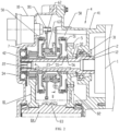
- FIG. 2 is a cross-sectional view of a transmission according to an embodiment of the present invention.
- the transmission includes a rotary shaft, a target gear, and the cone clutch 50 according to any one of the above embodiments.
- the target gear is sleeved over the rotary shaft and rotatable relative to the rotary shaft.
- the cone clutch 50 is configured to engage or disengage the rotary shaft and the target gear. That is, the rotary shaft and the target gear are the two to-be-engaged members as described above.
- the rotary shaft herein may be any one of an input shaft 2, an intermediate shaft, and/or a transmission output shaft 84, or a combination thereof, as long as the rotary shaft is a shaft for which the clutch is required.
- the transmission includes two clutches with friction pairs having conical ring surfaces.
- the outer ring 61 By controlling the axial movement of the outer ring 61, it is possible to control the engagement and disengagement of the cone clutch 50, thereby engaging or disengaging the to-be-engaged members.
- the arrangement of two sets of friction pairs with the conical ring surfaces can reduce the control force of the clutch and enhance the torque capability of the clutch.
- the target gear is disposed at the rotary shaft through a support bearing 32, which enables the target gear to rotate relative to the rotary shaft.
- the transmission further includes a gear coupling disc 51.
- the gear coupling disc 51 is fixedly connected to the target gear.
- the middle cone ring 53 is connected to the gear coupling disc 51 through a latch in an anti-relative rotation manner, and is slidable axially relative to the gear coupling disc 51.
- the inner ring 52 is connected to the outer ring 61 through a latch in an anti-relative rotation manner. An end of the inner ring 52 abuts against the gear coupling disc 51 to avoid an axial movement of the inner ring 52 when the clutch is engaged.
- the outer ring 61 is sleeved over the rotary shaft, and connected to the rotary shaft in an anti-relative rotation manner.
- the cone clutch 50 is interposed between the rotary shaft and the target gear. With this arrangement, the rotary shaft rotates synchronously with the outer ring 61. When the cone clutch 50 is engaged, the rotary shaft can synchronously drive the target gear to rotate through the cone clutch 50.
- a latch is disposed on a side of the middle cone ring 53 close to the gear coupling disc 51, and the latch protrudes in an axial direction of the middle cone ring 53.
- a first groove is formed at the gear coupling disc 51, and the latch is engaged into the first groove. Relative rotation between the middle conical ring 53 and the gear coupling disc 51 can be avoided by the arrangement of the latch and the first groove.
- the outer ring 61 is connected to the rotary shaft through a spline key 22, thus avoid a relative rotation therebetween. Meanwhile, the outer ring 61 may also be movable axially relative to the rotary shaft.
- the cone clutch 50 includes a reset spring 55.
- the transmission further includes a retainer ring 56 sleeved over the rotary shaft.
- the retainer ring 56 has a side in contact with the target gear and another side abutting against the reset spring 55.
- the retainer ring 56 is configured to restrict an axial displacement of the target gear, and further provides an abutting surface for an end of the reset spring 55.
- the cone clutch 50 can automatically be restored by the arrangement of the reset spring 55.
- the transmission further includes a circlip 23 sleeved over the rotary shaft and located at a side of the outer ring 61 away from the reset spring 55.
- the circlip 23 is configured to restrict an axial displacement of the outer ring 61.
- FIG. 3 is a partially enlarged view at part A illustrated in FIG. 2 .
- the transmission further includes an actuator.
- the actuator includes a motor 10, a second gear 62, a nut 63, and a screw 64.
- a first gear 101 is disposed on an output shaft of the motor 10.
- the first gear 101 may be a gear sleeved over on the output shaft of the motor 10 or a gear machined on the output shaft of the motor 10.
- the second gear 62 is meshed with the first gear 101.
- the second gear 62 is sleeved over an outer surface of the nut 63.
- the screw 64 forms a screw pair with an inner wall of the nut 63.
- the screw 64 is fixedly connected to a housing of the transmission to enable the nut 63 to be axially displaced to generate a thrust directly or indirectly acting on the outer ring 61 when the second gear 62 and the nut 63 are driven by the motor 10 to rotate relative to the screw 64.
- a speed ratio of the first gear 101 to the second gear 62 is any value from 10 to 20, such as 10, 15, or 20.
- an output torque of 0.8 Nm of the motor 10 is sufficient to generate an axial force of 3 kN or more for the engagement of the clutch.
- the nut 63 When the torque is output from the motor 10, power is transmitted to the nut 63 through the gear pair. As the screw 64 is fixed, the nut 63 then rotates relative to the screw 64 and generates an axial displacement, thereby urging the cone clutch 50 for the engagement or the disengagement. Certainly, in other embodiments, the nut 63 may also be fixed, and the screw 64 is driven by the motor 10 through the gear pair, which is also capable of outputting an axial thrust.
- the transmission further includes the actuator, which is driven by the gear pair and the screw pair. Since a driving force may be amplified by the gear pair, the screw pair, and the friction pairs with the conical surfaces, the engagement of the cone clutch 50 may be controlled by means of a small motor 10.
- a driving torque of 10 Nm may be converted into an axial force of 2500 N by means of one screw pair.
- a simple pair of gear reducers may amplify the output torque of the motor 10 by a factor of ten or more.
- a small motor 10 with two hundred watts may transmit a torque of 300Nm by means of a simple gear reducer, a pair of screw pairs, and two friction conical surfaces, thereby satisfying requirement for driving power of a general electric vehicle.
- a motor 10 with an operating torque of smaller than 1Nm is enough to drive the cone clutch 50 of 350Nm.
- the actuator according to this embodiment can save power consumption, thereby improving the efficiency of the transmission.
- a conventional automotive transmission clutch is generally a multi-plate and wet clutch, and its actuator is an electro-hydraulically controlled hydraulic cylinder.
- the actuator includes a hydraulic pump, a hydraulic cylinder, a proportional pressure solenoid valve, and a valve plate. Therefore, only the motor 10 is required for a power source of the actuator in this embodiment, thereby lowering manufacturing cost of the actuator.
- the screw pair formed by the nut 63 and the screw 64 in the actuator may be replaced with a ball screw (not shown), thereby reducing frictional resistance and saving control power.
- the transmission further includes a first buffer assembly disposed between the nut 63 of the actuator and the outer ring 61.
- the first buffer assembly includes a radial positioning ring 661, a first thrust bearing 331, and a first spring diaphragm 541 that sequentially abut against each other.
- a side of the radial positioning ring 661 away from the first thrust bearing 331 abuts against the nut 63 to restrict a radial displacement of the first thrust bearing 331.
- a side of the first spring diaphragm 541 away from the first thrust bearing 331 abuts against the outer ring 61 of the cone clutch 50 at a side where the first spring diaphragm 541 is located.
- the first spring diaphragm 541 is disposed between the first thrust bearing 331 and the outer ring 61, and serves to buffer an impact of the nut 63 to avoid an impact of the clutch during its engagement.
- a plurality of cone clutches 50, a plurality of actuators, and a plurality of first buffer assemblies are provided and are same in quantity.
- the plurality of cone clutches 50 is arranged in one-to-one correspondence with the plurality of actuators and the plurality of first buffer assemblies. That is, only one actuator can drive the corresponding one of the plurality of cone clutches, with one first buffer assembly interposed therebetween.
- two cone clutches are provided.
- the outer rings 61 of the two cone clutches 50 are located at two sides of the nut 63, respectively.
- the motor 10 is configured to output forward torque and backward torque to enable the two cone clutches 50 to share one actuator.
- the transmission further includes a first buffer assembly, a second buffer assembly, and an anti-loosening spring 65.
- the first buffer assembly and the second buffer assembly are located at two sides of the nut 63 in an axial direction of the nut 63, respectively.
- the anti-loosening spring 65 is disposed in an axial through hole of the nut 63, and has two ends respectively abutting against the first buffer assembly and the second buffer assembly.
- the first buffer assembly includes a radial positioning ring 661, a first thrust bearing 331, and a first spring diaphragm 541 that sequentially abut against each other.
- a side of the radial positioning ring 661 away from the first thrust bearing 331 abuts against the nut 63 and is connected to an end of the anti-loosening spring 65, to restrict a radial displacement of the first thrust bearing 331.
- a side of the first spring diaphragm 541 away from the first thrust bearing 331 abuts against the outer ring 61 of the cone clutch 50 at a side where the first spring diaphragm 541 is located.
- the radial positioning ring 661 is substantially in a "Z" shape and has two radial surfaces that respectively abut against the first thrust bearing 331 and the nut 63, thereby radially positioning the first thrust bearing 331.
- the second buffer assembly includes a second thrust bearing 332, a gasket 662, a transition ring 67, a third thrust bearing 333, and a second spring diaphragm 542 that sequentially abut against each other in an axial direction of the rotary shaft.
- An end surface of the second thrust bearing 332 away from the gasket 662 is connected to the anti-loosening spring 65.
- a side of the second spring diaphragm 542 away from the transition ring 67 abuts against the outer ring 61 of the cone clutch 50 at a side where the second spring diaphragm 542 is located.
- the anti-loosening spring is configured to allow a predetermined pre-tightening force to be always generated between various components of the second buffer assembly, thus reducing noise during the shifting.
- a second groove 651 is formed at an end surface of the nut 63 away from the first buffer assembly.
- the second groove 651 radially penetrates an outer ring surface of the nut 63.
- Both the second thrust bearing 332 and the gasket 662 are disposed within the second groove 651, and are engaged with a bottom surface of the second groove 651 in a radial direction of the second groove 651, thereby restricting radial displacements of the second thrust bearing 332 and the gasket 662.
- a first boss 672 and a second boss 673 are disposed on two sides of the transition ring 67 in an axial direction of the transition ring 67, respectively.
- the first boss 672 is engaged with a circumferential surface of the gasket 662 to restrict a radial displacement of the transition ring 67.
- the second boss 673 is engaged with a circumferential surface of the third thrust bearing 333 to restrict a radial displacement of the third thrust bearing 333.
- the radial positioning is based on the nut 63 to sequentially restrict the radial displacement of each of the second thrust bearing 332, the gasket 662, the transition ring 67, and the third thrust bearing 333.
- other radial positioning manners may be used, for example, by providing radial engagement features on the screw 64 and the transition ring 67, using the screw 64 to radially position the transition ring 67, which in turn positions the second thrust bearing 332 and the third thrust bearing 333.
- FIG. 4 is a cross-sectional view taking along line B-B illustrated in FIG. 2 .
- the screw 64 has a plurality of connection arms 641.
- Each of the plurality of connection arms 641 is fixedly connected to the housing of the transmission.
- the plurality of connection arms 641 is evenly arranged in a circumferential direction of the screw 64.
- Each of the plurality of connection arms 641 protrudes from the screw 64 in a radial direction of the screw 64. Accordingly, it is necessary for the transition ring 67 to have a plurality of radial through groove 671 to allow each of the connection arms to pass therethrough.
- the through groove 671 should also perpetrate an axial side of the transition ring 67 to facilitate an axial assembly between the transition ring 67 and the screw 64.
- a plurality of grooves is formed at an end surface of the transition ring 67 in an axial direction of the transition ring 67.
- the plurality of grooves may be covered with a gasket 662 disposed on this end surface, thereby facilitating abutment of the thrust bearing (the second thrust bearing 332 in the embodiment of FIG. 2 ) to realized more stable force transmission.
- FIG. 5 is a schematic principle view of a transmission according to an embodiment of the present invention.
- FIG. 6 is a schematic view of a radial arrangement of the transmission of FIG. 5 .
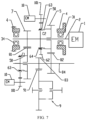
- FIG. 7 is a schematic principle view of a transmission according to another embodiment of the present invention.
- one actuator it is possible for one actuator to control one cone clutch 50 alone (see FIG. 7 ), and it is also possible for one actuator to provide two adjacent cone clutches 50 with braking power simultaneously (see FIG. 5 ).
- two cone clutches 50, two actuators, and two first buffer assemblies are provided, and the two cone clutch 50 are arranged in one-to-one correspondence with the two actuators and the two first buffer assemblies.
- one cone clutch 50 it is possible to control one cone clutch 50 by one actuator individually.
- one actuator is shared by the two cone clutches 50, there is a short (tens of milliseconds) power interruption during the shifting, which is not normally felt.
- one cone clutch 50 is controlled by one actuator alone, an unpowered interruption can be achieved, and thus the shifting is smoother.
- the rotary shaft includes a transmission input shaft 2 and/or a transmission output shaft 84.
- the cone clutch may be arranged as required.
- separate cone clutches 50 are provided for different rotary shafts depending on a space arrangement requirement.
- the cone clutch 50 may also be disposed on the intermediate shaft.
- At least two sets of variable gears are provided on the transmission input shaft 2 and the transmission output shaft 84, and the target gears are all driving gears on the transmission input shaft 2 or all driven gears on the transmission output shaft 84; or the target gears are at least one driving gear on the transmission input shaft 2 and a driven gear, in no mesh with the at least one driving gear, on the transmission output shaft 84.
- the transmission input shaft 2 is connected to an output shaft of a prime motor 1, for example, through the spline key 12.
- Two ends of the transmission input shaft 2 may be supported on a front housing 41 and a rear housing 42 by a first bearing 31 and a second bearing 34, respectively.
- Two sets of variable gears are provided on the transmission input shaft 2 and the transmission output shaft 84.
- An output gear 83 is further provided on the transmission output shaft 84 and is connected to a differential 9.
- a first driving gear 7 and a second driving gear 5 are provided on the transmission input shaft 2.
- first driven gear 81 and a second driven gear 82 are provided on the transmission output shaft 84, and are meshed with the first driving gear 7 and the second driving gear 5, respectively.
- the first driving gear 7 and the first driven gear are formed into a low-speed gear pair
- the second driving gear 5 and the second driven gear are formed into a high-speed gear pair.
- One cone clutch 50 is connected in series between the first driving gear 7 and the transmission input shaft 2
- one cone clutch 50 is connected in series between the second driving gear 5 and the transmission input shaft 2.
- the output gear 83 is further provided on the transmission output shaft 84.
- the output gear 83 (equivalent to a driving gear of the differential 9) is meshed with a differential gear 91 of the differential 9 to transmit the power to wheels through the differential 9 and a half shaft.
- Such a two-speed transmission is particularly suitably used as a transmission for an electric vehicles of not too great power.
- the gear coupling disc 51 can avoid the axial movement of the inner cone ring 52, the outer ring 61 urges the middle cone ring 53 to be pressed against the inner cone ring 52 to generate friction torque at both the inner ring surface and outer ring surface 61 of the middle cone ring 53, thereby engaging the cone clutch 50.
- the power from the transmission input shaft 2 is transmitted to the first driving gear 7 at the left side of the actuator to allow the transmission to operate in low gear.
- the motor 10 is controlled to be disconnected and is self-locking by means of the screw pair.
- the motor 10 is controlled to output the backward torque, and the nut 63 is returned back to its neutral position.
Landscapes
- Engineering & Computer Science (AREA)
- General Engineering & Computer Science (AREA)
- Mechanical Engineering (AREA)
- Mechanical Operated Clutches (AREA)
Claims (14)
- Konuskupplung (50), umfassend:einen mittleren Konusring (53), dessen innere und äußere Ringflächen beide Konusflächen sind;einen inneren Konusring (52), der an der Innenseite des mittleren Konusrings (53) angeordnet ist, wobei eine äußere Ringfläche des inneren Konusrings (52) eine Konusfläche ist, die zur inneren Ringfläche des mittleren Konusrings (53) passt; sowieeinen äußeren Ring (61), der eine mit der äußeren Ringfläche des mittleren Konusrings (53) übereinstimmende konische Ringfläche aufweist,wobei der äußere Ring (61) relativ zu dem inneren Konusring (52) in einer axialen Richtung der konischen Ringfläche beweglich ist,wobei der mittlere Konusring (53) und der äußere Ring (61) jeweils mit zwei einzukuppelnden Elementen verbunden sind,wobei die Konuskupplung (50) so konfiguriert ist, dass, wenn der äußere Ring (61) einem Schub ausgesetzt ist, der den äußere Ring (61) in Richtung des mittleren Konusrings (53) drängt, die zwei einzukuppelnden Elemente dadurch einzukuppeln, dass Reibungspaaren in engem Kontakt zwischen dem äußeren Ring (61) und dem mittleren Konusring (53) sowie zwischen dem mittleren Konusring (53) und dem inneren Konusring (52) gebildet werden,dadurch gekennzeichnet, dass die Konuskupplung (50) ferner eine Rückstellfeder (55) umfasst, wobei ein Ende der Rückstellfeder (55) fest angeordnet ist, und wobei das andere Ende der Rückstellfeder (55) mit dem äußeren Ring (61) verbunden ist.
- Getriebe, umfassendeine Drehwelle,ein Zielzahnrad, das auf die Drehwelle aufgesetzt wird und relativ zur Drehwelle drehbar ist; undeine Konuskupplung (50) nach Anspruch 1, wobei die Konuskupplung (50) so konfiguriert ist, dass sie die Drehwelle und das Zielzahnrad ein- oder auskuppelt.
- Getriebe nach Anspruch 2, wobei das Zielzahnrad über ein Stützlager (32) an der Drehwelle angeordnet ist.
- Getriebe nach Anspruch 2, ferner eine Zahnradkupplungsscheibe (51) umfassend, die fest mit dem Zielzahnrad und drehfest mit dem mittleren Konusring (53) verbunden ist,
wobei der äußere Ring (61) auf die Drehwelle aufgesetzt wird und die beiden eine drehfeste Verbindung bilden. - Getriebe nach Anspruch 4, wobei eine nahe der Zahnradkupplungsscheibe (51) liegende Seite des mittleren Konusrings (53) mit einem Rastzahn versehen ist, der entlang der axialen Richtung des mittleren Konusrings hervorsteht, und wobei die Zahnradkupplungsscheibe (51) mit einer ersten Nut versehen ist, in die der Rastzahn eingreift; oder
wobei der äußere Ring (61) über eine Keilverzahnung (22) mit der Drehwelle verbunden ist. - Getriebe nach Anspruch 4, wobei die Konuskupplung (50) eine Rückstellfeder (55) umfasst,
wobei das Getriebe ferner einen Sicherungsring (56) umfasst, der auf die Drehwelle aufgesetzt wird, wobei eine Seite des Sicherungsrings (56) in Kontakt mit dem Zielzahnrad steht, und wobei die andere Seite des Sicherungsrings (56) an der Rückstellfeder (55) anliegt. - Getriebe nach Anspruch 6, ferner ein Klemmfutter (23) umfassend, das auf die Drehwelle aufgesetzt wird und sich an einer von der Rückstellfeder (55) abgewandten Seite des äußeren Rings (61) befindet, wobei der Klemmfutter (23) dazu ausgelegt ist, eine axiale Verschiebung des äußeren Rings (61) zu begrenzen.
- Getriebe nach einem der Ansprüche 3 bis 6, ferner einen Aktuator umfassend, wobei der Aktuator umfasst:einen Motor (10), wobei ein erstes Zahnrad (101) auf einer Ausgangswelle des Motors (10) angeordnet ist;ein zweites Zahnrad (62), das mit dem ersten Zahnrad (101) in Eingriff steht;eine Mutter (63), wobei das zweite Zahnrad (62) auf eine Außenfläche der Mutter (63) aufgesetzt wird; undeine Gewindestange (64), die mit einer Innenwand der Mutter (63) ein Spiralpaar bildet, wobei die Gewindestange (64) fest mit einem Gehäuse des Getriebes verbunden ist, sodass eine axiale Verschiebung der Mutter (63) einen Schub erzeugt, der direkt oder indirekt auf den äußeren Ring (61) wirkt, wenn das zweite Zahnrad (62) und die Mutter (63) durch den Motor (10) angetrieben werden, um sich relativ zur Gewindestange (64) zu drehen.
- Getriebe nach Anspruch 8, das ferner eine erste Pufferanordnung umfasst, die zwischen der Mutter (63) des Aktuators und dem äußeren Ring (61) angeordnet ist;wobei die erste Pufferanordnung einen radialen Positionierungsring (661), ein erstes Axiallager (331) und eine erste Federmembran (541) umfasst, die nacheinander aneinander anliegen, wobei eine vom ersten Axiallager (331) weg entfernte Seite des radialen Positionierungsrings (661) an die Mutter (63) anliegt, um eine radiale Verschiebung des ersten Axiallagers (331) zu begrenzen; und eine vom ersten Axiallager (331) weg entfernte Seite der ersten Federmembran (541) an den äußeren Ring (61) der Konuskupplung (50) an einer Seite anliegt, an der sich die erste Federmembran (541) befindet,wobei die Anzahl der Kegelkupplung (50), des Aktuators und der ersten Pufferanordnung eine Mehrzahl und gleich ist, und wobei jede der Konuskupplungen (50) eins-zu-eins mit einem der Aktuatoren und einer der ersten Pufferanordnungen entsprechend angeordnet ist.
- Getriebe nach Anspruch 8, wobei die Anzahl von Kegelkupplung (50) zwei beträgt, wobei sich die äußeren Ringe (61) der zwei konischen Kupplungen (50) jeweils auf beiden Seiten der Mutter (63) befinden, wobei der Motor (10) so konfiguriert ist, dass er Vorwärtsdrehmoment und Rückwärtsdrehmoment ausgibt, so dass die zwei Konuskupplungen (50) gemeinsam einen Aktuator nutzen.
- Getriebe nach Anspruch 10, ferner umfassend:eine erste Pufferanordnung und eine zweite Pufferanordnung, die sich jeweils an zwei axialen Seiten der Mutter (63) befinden; undeine Anti-Lockerungsfeder (65), die in ein axiales Durchgangsloch der Mutter (63) eingesetzt ist, wobei zwei Enden der Anti-Lockerungsfeder (65) jeweils mit der ersten Pufferanordnung und der zweiten Pufferanordnung in Kontakt stehen.
- Getriebe nach Anspruch 11, wobei die erste Pufferanordnung einen radialen Positionierungsring (661), ein erstes Axiallager (331) und eine erste Federmembran (541) umfasst, die nacheinander aneinander anliegen, wobei eine vom ersten Axiallager (331) weg entfernte Seite des radialen Positionierungsrings (661) an die Mutter (63) anliegt und gleichzeitig mit einem Ende der Anti-Lockerungsfeder (65) verbunden ist, um eine radiale Verschiebung des ersten Axiallagers (331) zu begrenzen; und wobei eine vom ersten Axiallager (331) weg entfernte Seite der ersten Federmembran (541) an den äußeren Ring (61) der Konuskupplung (50) an einer Seite anliegt, an der sich die erste Federmembran (541) befindet.
- Getriebe nach Anspruch 11, wobei die zweite Pufferanordnung ein zweites Axiallager (332), eine Unterlagescheibe (662), einen Übergangsring (67), ein drittes Axiallager (333) und eine zweite Federmembran (542) umfasst, die nacheinander entlang der Axialrichtung der Drehwelle aneinander anliegen, wobei eine Endfläche einer von der Unterlagescheibe (662) weg entfernten Seite des zweiten Axiallagers (332) mit der Anti-Lockerungsfeder (65) verbunden ist, wobei eine von dem Übergangsring (67) weg entfernte Seite der zweiten Federmembran (542) an den äußeren Ring (61) der Konuskupplung (50) an einer Seite anliegt, an der sich die zweite Federmembran (542) befindet,wobei an einer von der ersten Pufferanordnung weg entfernten Endfläche der Mutter (63) eine zweite Nut (651) vorgesehen ist, die auch radial durch die äußere Ringfläche der Mutter (63) durchdringt;wobei sowohl das zweite Axiallager (332) als auch die Unterlagescheibe (662) auf die zweite Nut (651) aufgesetzt werden und mit einer Bodenfläche in radialer Richtung der zweiten Nut (651) in Eingriff sind;wobei ein erster Vorsprung (672) und ein zweiter Vorsprung (673) an zwei Seiten des Übergangsrings (67) in axialer Richtung des Übergangsrings angeordnet sind, wobei der erste Vorsprung (672) mit einer Umfangsfläche der Unterlagescheibe (662) in Eingriff ist, um eine radiale Verschiebung des Übergangsrings (67) zu begrenzen, und wobei der zweite Vorsprung (673) mit einer Umfangsfläche des dritten Axiallagers (333) in Eingriff ist, um eine radiale Verschiebung des dritten Axiallagers (333) zu begrenzen.
- Getriebe nach Anspruch 8, wobei die Gewindestange (64) eine Vielzahl von Verbindungsarmen (641) umfasst, wobei jeder der Verbindungsarme (641) fest mit dem Gehäuse des Getriebes verbunden ist,
wobei die Vielzahl von Verbindungsarmen (641) gleichmäßig in Umfangsrichtung der Gewindestange (64) angeordnet ist, und wobei jeder der Verbindungsarme (641) in radialer Richtung der Gewindestange (64) hervorragt.
Applications Claiming Priority (1)
| Application Number | Priority Date | Filing Date | Title |
|---|---|---|---|
| PCT/CN2021/107125 WO2023000138A1 (zh) | 2021-07-19 | 2021-07-19 | 锥形离合器及变速器 |
Publications (4)
| Publication Number | Publication Date |
|---|---|
| EP4246007A1 EP4246007A1 (de) | 2023-09-20 |
| EP4246007A4 EP4246007A4 (de) | 2024-04-10 |
| EP4246007B1 true EP4246007B1 (de) | 2025-04-23 |
| EP4246007C0 EP4246007C0 (de) | 2025-04-23 |
Family
ID=84979643
Family Applications (1)
| Application Number | Title | Priority Date | Filing Date |
|---|---|---|---|
| EP21950404.0A Active EP4246007B1 (de) | 2021-07-19 | 2021-07-19 | Kegelkupplung und getriebe |
Country Status (3)
| Country | Link |
|---|---|
| EP (1) | EP4246007B1 (de) |
| CN (1) | CN116635641B (de) |
| WO (1) | WO2023000138A1 (de) |
Family Cites Families (15)
| Publication number | Priority date | Publication date | Assignee | Title |
|---|---|---|---|---|
| JP3378138B2 (ja) * | 1996-02-16 | 2003-02-17 | 日野自動車株式会社 | 手動変速機に使用される同期装置 |
| JP4436603B2 (ja) * | 2000-11-03 | 2010-03-24 | セレクト デザイン テクノロジーズ リミテッド | コーン選択装置及びそれに関するトランスミッション組立体 |
| FR2826701B1 (fr) * | 2001-06-29 | 2003-09-26 | Renault | Boite de vitesses a arbres paralleles et procede de commande des changements de rapports correspondants |
| CN1544824A (zh) * | 2003-11-20 | 2004-11-10 | 上海汽车股份有限公司 | 三锥面同步器 |
| AT502647B1 (de) * | 2004-01-15 | 2007-05-15 | Miba Sinter Austria Gmbh | Synchronisierring für ein zahnradwechselgetriebe |
| RU2360158C2 (ru) * | 2004-05-28 | 2009-06-27 | Интернэшнл Инновейшнз Лимитед | Муфта сцепления |
| DE102009012961B3 (de) * | 2009-03-12 | 2010-01-21 | Ab Skf | Verfahren zur Herstellung eines Ringes einer Synchronisationseinrichtung und Ring einer Synchronisationseinrichtung |
| DE102012213999B3 (de) * | 2012-08-07 | 2013-11-07 | Zf Friedrichshafen Ag | Mehrfachkonussynchronisieranordnung |
| DE102012220563A1 (de) * | 2012-11-12 | 2014-05-15 | Zf Friedrichshafen Ag | Reibschlüssiges Schaltelement |
| CN103388656B (zh) * | 2013-08-08 | 2017-02-08 | 中国重汽集团济南动力有限公司 | 一种10档双中间轴同步器变速箱 |
| KR101866077B1 (ko) * | 2016-10-21 | 2018-06-11 | 현대자동차주식회사 | 차량의 클러치 |
| DE102018111248A1 (de) * | 2018-05-09 | 2019-11-14 | Hoerbiger Antriebstechnik Holding Gmbh | Synchronkupplung |
| DE102018111176A1 (de) * | 2018-05-09 | 2019-11-14 | Hoerbiger Antriebstechnik Holding Gmbh | Synchronisierkupplung |
| DE102018119199A1 (de) * | 2018-08-07 | 2020-02-13 | Hoerbiger Antriebstechnik Holding Gmbh | Antriebsstrang eines elektrisch angetriebenen Fahrzeugs und elektrisch angetriebenes Fahrzeug |
| CN110985616A (zh) * | 2019-12-31 | 2020-04-10 | 綦江齿轮传动有限公司 | 一种变速器的三锥同步器 |
-
2021
- 2021-07-19 EP EP21950404.0A patent/EP4246007B1/de active Active
- 2021-07-19 CN CN202180075453.9A patent/CN116635641B/zh active Active
- 2021-07-19 WO PCT/CN2021/107125 patent/WO2023000138A1/zh not_active Ceased
Also Published As
| Publication number | Publication date |
|---|---|
| EP4246007A1 (de) | 2023-09-20 |
| EP4246007A4 (de) | 2024-04-10 |
| EP4246007C0 (de) | 2025-04-23 |
| CN116635641B (zh) | 2025-11-28 |
| CN116635641A (zh) | 2023-08-22 |
| WO2023000138A1 (zh) | 2023-01-26 |
Similar Documents
| Publication | Publication Date | Title |
|---|---|---|
| RU2529113C2 (ru) | Коробка передач с несколькими сцеплениями для транспортного средства | |
| US8584823B2 (en) | Torque transmitting assembly with dog clutch and plate clutch features | |
| US6835158B2 (en) | Automatic transmission | |
| US20110167957A1 (en) | Automatic dual-clutch transmission | |
| KR20020070482A (ko) | 육상 차량, 특히 자동차용 변속 장치 | |
| WO2013062017A1 (ja) | 電気自動車用駆動装置 | |
| CN107407378B (zh) | 具有花键的双中间轴变速器 | |
| EP3580475B1 (de) | Getriebe für fahrzeuge | |
| US11859696B2 (en) | Module for a system for synchronizing and driving a transmission gearbox countershaft | |
| WO2023185518A1 (zh) | 行星排变速器、动力总成和车辆 | |
| CN108443434B (zh) | 电动汽车变速器用单作动器换挡执行机构及变速器 | |
| EP3580474B1 (de) | Getriebe für fahrzeuge | |
| US20050155826A1 (en) | Friction engaging device | |
| EP3580476B1 (de) | Getriebe für fahrzeuge | |
| EP4246007B1 (de) | Kegelkupplung und getriebe | |
| US20150354700A1 (en) | Automatic transmission | |
| JP2004211834A (ja) | 多段変速機及びその変速制御装置 | |
| CN113236730A (zh) | 一种新型无级变速器 | |
| CN113446326A (zh) | 带有锥形表面的离合器总成压盘 | |
| JPH10331869A (ja) | クラッチの潤滑装置 | |
| CN101317019A (zh) | 用于防止车辆变速装置中齿式离合器内脱档的装置 | |
| JP2023098321A (ja) | 車両用動力伝達装置 | |
| JPS63246561A (ja) | 無段変速装置 | |
| JP5045805B2 (ja) | トロイダル型無段変速機 | |
| JP2003278808A (ja) | 自動変速装置 |
Legal Events
| Date | Code | Title | Description |
|---|---|---|---|
| STAA | Information on the status of an ep patent application or granted ep patent |
Free format text: STATUS: THE INTERNATIONAL PUBLICATION HAS BEEN MADE |
|
| PUAI | Public reference made under article 153(3) epc to a published international application that has entered the european phase |
Free format text: ORIGINAL CODE: 0009012 |
|
| STAA | Information on the status of an ep patent application or granted ep patent |
Free format text: STATUS: REQUEST FOR EXAMINATION WAS MADE |
|
| 17P | Request for examination filed |
Effective date: 20230614 |
|
| AK | Designated contracting states |
Kind code of ref document: A1 Designated state(s): AL AT BE BG CH CY CZ DE DK EE ES FI FR GB GR HR HU IE IS IT LI LT LU LV MC MK MT NL NO PL PT RO RS SE SI SK SM TR |
|
| REG | Reference to a national code |
Ref country code: DE Ref legal event code: R079 Free format text: PREVIOUS MAIN CLASS: F16D0013240000 Ipc: F16D0023040000 Ref country code: DE Ref legal event code: R079 Ref document number: 602021029830 Country of ref document: DE Free format text: PREVIOUS MAIN CLASS: F16D0013240000 Ipc: F16D0023040000 |
|
| A4 | Supplementary search report drawn up and despatched |
Effective date: 20240307 |
|
| RIC1 | Information provided on ipc code assigned before grant |
Ipc: F16D 13/24 20060101ALI20240301BHEP Ipc: F16D 23/04 20060101AFI20240301BHEP |
|
| RAP1 | Party data changed (applicant data changed or rights of an application transferred) |
Owner name: WUXI INFIMOTION TECHNOLOGY CO., LTD. |
|
| DAV | Request for validation of the european patent (deleted) | ||
| DAX | Request for extension of the european patent (deleted) | ||
| GRAP | Despatch of communication of intention to grant a patent |
Free format text: ORIGINAL CODE: EPIDOSNIGR1 |
|
| STAA | Information on the status of an ep patent application or granted ep patent |
Free format text: STATUS: GRANT OF PATENT IS INTENDED |
|
| RIC1 | Information provided on ipc code assigned before grant |
Ipc: F16D 13/24 20060101ALI20241114BHEP Ipc: F16D 23/04 20060101AFI20241114BHEP |
|
| INTG | Intention to grant announced |
Effective date: 20241211 |
|
| GRAS | Grant fee paid |
Free format text: ORIGINAL CODE: EPIDOSNIGR3 |
|
| GRAA | (expected) grant |
Free format text: ORIGINAL CODE: 0009210 |
|
| STAA | Information on the status of an ep patent application or granted ep patent |
Free format text: STATUS: THE PATENT HAS BEEN GRANTED |
|
| AK | Designated contracting states |
Kind code of ref document: B1 Designated state(s): AL AT BE BG CH CY CZ DE DK EE ES FI FR GB GR HR HU IE IS IT LI LT LU LV MC MK MT NL NO PL PT RO RS SE SI SK SM TR |
|
| REG | Reference to a national code |
Ref country code: GB Ref legal event code: FG4D |
|
| REG | Reference to a national code |
Ref country code: CH Ref legal event code: EP |
|
| REG | Reference to a national code |
Ref country code: DE Ref legal event code: R096 Ref document number: 602021029830 Country of ref document: DE |
|
| REG | Reference to a national code |
Ref country code: IE Ref legal event code: FG4D |
|
| U01 | Request for unitary effect filed |
Effective date: 20250522 |
|
| U07 | Unitary effect registered |
Designated state(s): AT BE BG DE DK EE FI FR IT LT LU LV MT NL PT RO SE SI Effective date: 20250602 |
|
| PGFP | Annual fee paid to national office [announced via postgrant information from national office to epo] |
Ref country code: GB Payment date: 20250617 Year of fee payment: 5 |
|
| U20 | Renewal fee for the european patent with unitary effect paid |
Year of fee payment: 5 Effective date: 20250610 |
|
| PG25 | Lapsed in a contracting state [announced via postgrant information from national office to epo] |
Ref country code: ES Free format text: LAPSE BECAUSE OF FAILURE TO SUBMIT A TRANSLATION OF THE DESCRIPTION OR TO PAY THE FEE WITHIN THE PRESCRIBED TIME-LIMIT Effective date: 20250423 |
|
| PG25 | Lapsed in a contracting state [announced via postgrant information from national office to epo] |
Ref country code: NO Free format text: LAPSE BECAUSE OF FAILURE TO SUBMIT A TRANSLATION OF THE DESCRIPTION OR TO PAY THE FEE WITHIN THE PRESCRIBED TIME-LIMIT Effective date: 20250723 Ref country code: GR Free format text: LAPSE BECAUSE OF FAILURE TO SUBMIT A TRANSLATION OF THE DESCRIPTION OR TO PAY THE FEE WITHIN THE PRESCRIBED TIME-LIMIT Effective date: 20250724 |
|
| PG25 | Lapsed in a contracting state [announced via postgrant information from national office to epo] |
Ref country code: PL Free format text: LAPSE BECAUSE OF FAILURE TO SUBMIT A TRANSLATION OF THE DESCRIPTION OR TO PAY THE FEE WITHIN THE PRESCRIBED TIME-LIMIT Effective date: 20250423 |
|
| PG25 | Lapsed in a contracting state [announced via postgrant information from national office to epo] |
Ref country code: HR Free format text: LAPSE BECAUSE OF FAILURE TO SUBMIT A TRANSLATION OF THE DESCRIPTION OR TO PAY THE FEE WITHIN THE PRESCRIBED TIME-LIMIT Effective date: 20250423 |
|
| PG25 | Lapsed in a contracting state [announced via postgrant information from national office to epo] |
Ref country code: RS Free format text: LAPSE BECAUSE OF FAILURE TO SUBMIT A TRANSLATION OF THE DESCRIPTION OR TO PAY THE FEE WITHIN THE PRESCRIBED TIME-LIMIT Effective date: 20250723 |
|
| PG25 | Lapsed in a contracting state [announced via postgrant information from national office to epo] |
Ref country code: IS Free format text: LAPSE BECAUSE OF FAILURE TO SUBMIT A TRANSLATION OF THE DESCRIPTION OR TO PAY THE FEE WITHIN THE PRESCRIBED TIME-LIMIT Effective date: 20250823 |
|
| PG25 | Lapsed in a contracting state [announced via postgrant information from national office to epo] |
Ref country code: SM Free format text: LAPSE BECAUSE OF FAILURE TO SUBMIT A TRANSLATION OF THE DESCRIPTION OR TO PAY THE FEE WITHIN THE PRESCRIBED TIME-LIMIT Effective date: 20250423 |
|
| PG25 | Lapsed in a contracting state [announced via postgrant information from national office to epo] |
Ref country code: CZ Free format text: LAPSE BECAUSE OF FAILURE TO SUBMIT A TRANSLATION OF THE DESCRIPTION OR TO PAY THE FEE WITHIN THE PRESCRIBED TIME-LIMIT Effective date: 20250423 |
|
| PG25 | Lapsed in a contracting state [announced via postgrant information from national office to epo] |
Ref country code: SK Free format text: LAPSE BECAUSE OF FAILURE TO SUBMIT A TRANSLATION OF THE DESCRIPTION OR TO PAY THE FEE WITHIN THE PRESCRIBED TIME-LIMIT Effective date: 20250423 |
|
| REG | Reference to a national code |
Ref country code: CH Ref legal event code: H13 Free format text: ST27 STATUS EVENT CODE: U-0-0-H10-H13 (AS PROVIDED BY THE NATIONAL OFFICE) Effective date: 20260224 |
|
| PLBE | No opposition filed within time limit |
Free format text: ORIGINAL CODE: 0009261 |
|
| STAA | Information on the status of an ep patent application or granted ep patent |
Free format text: STATUS: NO OPPOSITION FILED WITHIN TIME LIMIT |
|
| REG | Reference to a national code |
Ref country code: CH Ref legal event code: L10 Free format text: ST27 STATUS EVENT CODE: U-0-0-L10-L00 (AS PROVIDED BY THE NATIONAL OFFICE) Effective date: 20260304 |
|
| 26N | No opposition filed |
Effective date: 20260126 |