EP4246019A1 - Hochdruckgasbehälter und verfahren zur herstellung davon - Google Patents
Hochdruckgasbehälter und verfahren zur herstellung davon Download PDFInfo
- Publication number
- EP4246019A1 EP4246019A1 EP21891724.3A EP21891724A EP4246019A1 EP 4246019 A1 EP4246019 A1 EP 4246019A1 EP 21891724 A EP21891724 A EP 21891724A EP 4246019 A1 EP4246019 A1 EP 4246019A1
- Authority
- EP
- European Patent Office
- Prior art keywords
- thread portion
- stress
- metallic
- metallic cylinder
- lid
- Prior art date
- Legal status (The legal status is an assumption and is not a legal conclusion. Google has not performed a legal analysis and makes no representation as to the accuracy of the status listed.)
- Granted
Links
Images

Classifications
-
- F—MECHANICAL ENGINEERING; LIGHTING; HEATING; WEAPONS; BLASTING
- F17—STORING OR DISTRIBUTING GASES OR LIQUIDS
- F17C—VESSELS FOR CONTAINING OR STORING COMPRESSED, LIQUEFIED OR SOLIDIFIED GASES; FIXED-CAPACITY GAS-HOLDERS; FILLING VESSELS WITH, OR DISCHARGING FROM VESSELS, COMPRESSED, LIQUEFIED, OR SOLIDIFIED GASES
- F17C1/00—Pressure vessels, e.g. gas cylinder, gas tank, replaceable cartridge
- F17C1/14—Pressure vessels, e.g. gas cylinder, gas tank, replaceable cartridge constructed of aluminium; constructed of non-magnetic steel
-
- F—MECHANICAL ENGINEERING; LIGHTING; HEATING; WEAPONS; BLASTING
- F17—STORING OR DISTRIBUTING GASES OR LIQUIDS
- F17C—VESSELS FOR CONTAINING OR STORING COMPRESSED, LIQUEFIED OR SOLIDIFIED GASES; FIXED-CAPACITY GAS-HOLDERS; FILLING VESSELS WITH, OR DISCHARGING FROM VESSELS, COMPRESSED, LIQUEFIED, OR SOLIDIFIED GASES
- F17C1/00—Pressure vessels, e.g. gas cylinder, gas tank, replaceable cartridge
- F17C1/02—Pressure vessels, e.g. gas cylinder, gas tank, replaceable cartridge involving reinforcing arrangements
-
- F—MECHANICAL ENGINEERING; LIGHTING; HEATING; WEAPONS; BLASTING
- F16—ENGINEERING ELEMENTS AND UNITS; GENERAL MEASURES FOR PRODUCING AND MAINTAINING EFFECTIVE FUNCTIONING OF MACHINES OR INSTALLATIONS; THERMAL INSULATION IN GENERAL
- F16J—PISTONS; CYLINDERS; SEALINGS
- F16J12/00—Pressure vessels in general
-
- F—MECHANICAL ENGINEERING; LIGHTING; HEATING; WEAPONS; BLASTING
- F17—STORING OR DISTRIBUTING GASES OR LIQUIDS
- F17C—VESSELS FOR CONTAINING OR STORING COMPRESSED, LIQUEFIED OR SOLIDIFIED GASES; FIXED-CAPACITY GAS-HOLDERS; FILLING VESSELS WITH, OR DISCHARGING FROM VESSELS, COMPRESSED, LIQUEFIED, OR SOLIDIFIED GASES
- F17C1/00—Pressure vessels, e.g. gas cylinder, gas tank, replaceable cartridge
-
- F—MECHANICAL ENGINEERING; LIGHTING; HEATING; WEAPONS; BLASTING
- F17—STORING OR DISTRIBUTING GASES OR LIQUIDS
- F17C—VESSELS FOR CONTAINING OR STORING COMPRESSED, LIQUEFIED OR SOLIDIFIED GASES; FIXED-CAPACITY GAS-HOLDERS; FILLING VESSELS WITH, OR DISCHARGING FROM VESSELS, COMPRESSED, LIQUEFIED, OR SOLIDIFIED GASES
- F17C13/00—Details of vessels or of the filling or discharging of vessels
- F17C13/06—Closures, e.g. cap, breakable member
-
- F—MECHANICAL ENGINEERING; LIGHTING; HEATING; WEAPONS; BLASTING
- F17—STORING OR DISTRIBUTING GASES OR LIQUIDS
- F17C—VESSELS FOR CONTAINING OR STORING COMPRESSED, LIQUEFIED OR SOLIDIFIED GASES; FIXED-CAPACITY GAS-HOLDERS; FILLING VESSELS WITH, OR DISCHARGING FROM VESSELS, COMPRESSED, LIQUEFIED, OR SOLIDIFIED GASES
- F17C2201/00—Vessel construction, in particular geometry, arrangement or size
- F17C2201/01—Shape
- F17C2201/0104—Shape cylindrical
-
- F—MECHANICAL ENGINEERING; LIGHTING; HEATING; WEAPONS; BLASTING
- F17—STORING OR DISTRIBUTING GASES OR LIQUIDS
- F17C—VESSELS FOR CONTAINING OR STORING COMPRESSED, LIQUEFIED OR SOLIDIFIED GASES; FIXED-CAPACITY GAS-HOLDERS; FILLING VESSELS WITH, OR DISCHARGING FROM VESSELS, COMPRESSED, LIQUEFIED, OR SOLIDIFIED GASES
- F17C2201/00—Vessel construction, in particular geometry, arrangement or size
- F17C2201/01—Shape
- F17C2201/0104—Shape cylindrical
- F17C2201/0119—Shape cylindrical with flat end-piece
-
- F—MECHANICAL ENGINEERING; LIGHTING; HEATING; WEAPONS; BLASTING
- F17—STORING OR DISTRIBUTING GASES OR LIQUIDS
- F17C—VESSELS FOR CONTAINING OR STORING COMPRESSED, LIQUEFIED OR SOLIDIFIED GASES; FIXED-CAPACITY GAS-HOLDERS; FILLING VESSELS WITH, OR DISCHARGING FROM VESSELS, COMPRESSED, LIQUEFIED, OR SOLIDIFIED GASES
- F17C2201/00—Vessel construction, in particular geometry, arrangement or size
- F17C2201/01—Shape
- F17C2201/0138—Shape tubular
-
- F—MECHANICAL ENGINEERING; LIGHTING; HEATING; WEAPONS; BLASTING
- F17—STORING OR DISTRIBUTING GASES OR LIQUIDS
- F17C—VESSELS FOR CONTAINING OR STORING COMPRESSED, LIQUEFIED OR SOLIDIFIED GASES; FIXED-CAPACITY GAS-HOLDERS; FILLING VESSELS WITH, OR DISCHARGING FROM VESSELS, COMPRESSED, LIQUEFIED, OR SOLIDIFIED GASES
- F17C2201/00—Vessel construction, in particular geometry, arrangement or size
- F17C2201/05—Size
- F17C2201/056—Small (<1 m3)
-
- F—MECHANICAL ENGINEERING; LIGHTING; HEATING; WEAPONS; BLASTING
- F17—STORING OR DISTRIBUTING GASES OR LIQUIDS
- F17C—VESSELS FOR CONTAINING OR STORING COMPRESSED, LIQUEFIED OR SOLIDIFIED GASES; FIXED-CAPACITY GAS-HOLDERS; FILLING VESSELS WITH, OR DISCHARGING FROM VESSELS, COMPRESSED, LIQUEFIED, OR SOLIDIFIED GASES
- F17C2203/00—Vessel construction, in particular walls or details thereof
- F17C2203/06—Materials for walls or layers thereof; Properties or structures of walls or their materials
- F17C2203/0602—Wall structures; Special features thereof
- F17C2203/0604—Liners
-
- F—MECHANICAL ENGINEERING; LIGHTING; HEATING; WEAPONS; BLASTING
- F17—STORING OR DISTRIBUTING GASES OR LIQUIDS
- F17C—VESSELS FOR CONTAINING OR STORING COMPRESSED, LIQUEFIED OR SOLIDIFIED GASES; FIXED-CAPACITY GAS-HOLDERS; FILLING VESSELS WITH, OR DISCHARGING FROM VESSELS, COMPRESSED, LIQUEFIED, OR SOLIDIFIED GASES
- F17C2203/00—Vessel construction, in particular walls or details thereof
- F17C2203/06—Materials for walls or layers thereof; Properties or structures of walls or their materials
- F17C2203/0602—Wall structures; Special features thereof
- F17C2203/0607—Coatings
-
- F—MECHANICAL ENGINEERING; LIGHTING; HEATING; WEAPONS; BLASTING
- F17—STORING OR DISTRIBUTING GASES OR LIQUIDS
- F17C—VESSELS FOR CONTAINING OR STORING COMPRESSED, LIQUEFIED OR SOLIDIFIED GASES; FIXED-CAPACITY GAS-HOLDERS; FILLING VESSELS WITH, OR DISCHARGING FROM VESSELS, COMPRESSED, LIQUEFIED, OR SOLIDIFIED GASES
- F17C2203/00—Vessel construction, in particular walls or details thereof
- F17C2203/06—Materials for walls or layers thereof; Properties or structures of walls or their materials
- F17C2203/0602—Wall structures; Special features thereof
- F17C2203/0612—Wall structures
- F17C2203/0614—Single wall
- F17C2203/0617—Single wall with one layer
-
- F—MECHANICAL ENGINEERING; LIGHTING; HEATING; WEAPONS; BLASTING
- F17—STORING OR DISTRIBUTING GASES OR LIQUIDS
- F17C—VESSELS FOR CONTAINING OR STORING COMPRESSED, LIQUEFIED OR SOLIDIFIED GASES; FIXED-CAPACITY GAS-HOLDERS; FILLING VESSELS WITH, OR DISCHARGING FROM VESSELS, COMPRESSED, LIQUEFIED, OR SOLIDIFIED GASES
- F17C2203/00—Vessel construction, in particular walls or details thereof
- F17C2203/06—Materials for walls or layers thereof; Properties or structures of walls or their materials
- F17C2203/0602—Wall structures; Special features thereof
- F17C2203/0612—Wall structures
- F17C2203/0614—Single wall
- F17C2203/0619—Single wall with two layers
-
- F—MECHANICAL ENGINEERING; LIGHTING; HEATING; WEAPONS; BLASTING
- F17—STORING OR DISTRIBUTING GASES OR LIQUIDS
- F17C—VESSELS FOR CONTAINING OR STORING COMPRESSED, LIQUEFIED OR SOLIDIFIED GASES; FIXED-CAPACITY GAS-HOLDERS; FILLING VESSELS WITH, OR DISCHARGING FROM VESSELS, COMPRESSED, LIQUEFIED, OR SOLIDIFIED GASES
- F17C2203/00—Vessel construction, in particular walls or details thereof
- F17C2203/06—Materials for walls or layers thereof; Properties or structures of walls or their materials
- F17C2203/0634—Materials for walls or layers thereof
- F17C2203/0636—Metals
-
- F—MECHANICAL ENGINEERING; LIGHTING; HEATING; WEAPONS; BLASTING
- F17—STORING OR DISTRIBUTING GASES OR LIQUIDS
- F17C—VESSELS FOR CONTAINING OR STORING COMPRESSED, LIQUEFIED OR SOLIDIFIED GASES; FIXED-CAPACITY GAS-HOLDERS; FILLING VESSELS WITH, OR DISCHARGING FROM VESSELS, COMPRESSED, LIQUEFIED, OR SOLIDIFIED GASES
- F17C2203/00—Vessel construction, in particular walls or details thereof
- F17C2203/06—Materials for walls or layers thereof; Properties or structures of walls or their materials
- F17C2203/0634—Materials for walls or layers thereof
- F17C2203/0636—Metals
- F17C2203/0639—Steels
- F17C2203/0643—Stainless steels
-
- F—MECHANICAL ENGINEERING; LIGHTING; HEATING; WEAPONS; BLASTING
- F17—STORING OR DISTRIBUTING GASES OR LIQUIDS
- F17C—VESSELS FOR CONTAINING OR STORING COMPRESSED, LIQUEFIED OR SOLIDIFIED GASES; FIXED-CAPACITY GAS-HOLDERS; FILLING VESSELS WITH, OR DISCHARGING FROM VESSELS, COMPRESSED, LIQUEFIED, OR SOLIDIFIED GASES
- F17C2203/00—Vessel construction, in particular walls or details thereof
- F17C2203/06—Materials for walls or layers thereof; Properties or structures of walls or their materials
- F17C2203/0634—Materials for walls or layers thereof
- F17C2203/0636—Metals
- F17C2203/0648—Alloys or compositions of metals
-
- F—MECHANICAL ENGINEERING; LIGHTING; HEATING; WEAPONS; BLASTING
- F17—STORING OR DISTRIBUTING GASES OR LIQUIDS
- F17C—VESSELS FOR CONTAINING OR STORING COMPRESSED, LIQUEFIED OR SOLIDIFIED GASES; FIXED-CAPACITY GAS-HOLDERS; FILLING VESSELS WITH, OR DISCHARGING FROM VESSELS, COMPRESSED, LIQUEFIED, OR SOLIDIFIED GASES
- F17C2203/00—Vessel construction, in particular walls or details thereof
- F17C2203/06—Materials for walls or layers thereof; Properties or structures of walls or their materials
- F17C2203/0634—Materials for walls or layers thereof
- F17C2203/0658—Synthetics
- F17C2203/0663—Synthetics in form of fibers or filaments
-
- F—MECHANICAL ENGINEERING; LIGHTING; HEATING; WEAPONS; BLASTING
- F17—STORING OR DISTRIBUTING GASES OR LIQUIDS
- F17C—VESSELS FOR CONTAINING OR STORING COMPRESSED, LIQUEFIED OR SOLIDIFIED GASES; FIXED-CAPACITY GAS-HOLDERS; FILLING VESSELS WITH, OR DISCHARGING FROM VESSELS, COMPRESSED, LIQUEFIED, OR SOLIDIFIED GASES
- F17C2203/00—Vessel construction, in particular walls or details thereof
- F17C2203/06—Materials for walls or layers thereof; Properties or structures of walls or their materials
- F17C2203/0634—Materials for walls or layers thereof
- F17C2203/0658—Synthetics
- F17C2203/0663—Synthetics in form of fibers or filaments
- F17C2203/0673—Polymers
-
- F—MECHANICAL ENGINEERING; LIGHTING; HEATING; WEAPONS; BLASTING
- F17—STORING OR DISTRIBUTING GASES OR LIQUIDS
- F17C—VESSELS FOR CONTAINING OR STORING COMPRESSED, LIQUEFIED OR SOLIDIFIED GASES; FIXED-CAPACITY GAS-HOLDERS; FILLING VESSELS WITH, OR DISCHARGING FROM VESSELS, COMPRESSED, LIQUEFIED, OR SOLIDIFIED GASES
- F17C2203/00—Vessel construction, in particular walls or details thereof
- F17C2203/06—Materials for walls or layers thereof; Properties or structures of walls or their materials
- F17C2203/0634—Materials for walls or layers thereof
- F17C2203/0658—Synthetics
- F17C2203/0675—Synthetics with details of composition
-
- F—MECHANICAL ENGINEERING; LIGHTING; HEATING; WEAPONS; BLASTING
- F17—STORING OR DISTRIBUTING GASES OR LIQUIDS
- F17C—VESSELS FOR CONTAINING OR STORING COMPRESSED, LIQUEFIED OR SOLIDIFIED GASES; FIXED-CAPACITY GAS-HOLDERS; FILLING VESSELS WITH, OR DISCHARGING FROM VESSELS, COMPRESSED, LIQUEFIED, OR SOLIDIFIED GASES
- F17C2203/00—Vessel construction, in particular walls or details thereof
- F17C2203/06—Materials for walls or layers thereof; Properties or structures of walls or their materials
- F17C2203/068—Special properties of materials for vessel walls
- F17C2203/0695—Special properties of materials for vessel walls pre-constrained
-
- F—MECHANICAL ENGINEERING; LIGHTING; HEATING; WEAPONS; BLASTING
- F17—STORING OR DISTRIBUTING GASES OR LIQUIDS
- F17C—VESSELS FOR CONTAINING OR STORING COMPRESSED, LIQUEFIED OR SOLIDIFIED GASES; FIXED-CAPACITY GAS-HOLDERS; FILLING VESSELS WITH, OR DISCHARGING FROM VESSELS, COMPRESSED, LIQUEFIED, OR SOLIDIFIED GASES
- F17C2205/00—Vessel construction, in particular mounting arrangements, attachments or identifications means
- F17C2205/03—Fluid connections, filters, valves, closure means or other attachments
- F17C2205/0302—Fittings, valves, filters, or components in connection with the gas storage device
- F17C2205/0311—Closure means
-
- F—MECHANICAL ENGINEERING; LIGHTING; HEATING; WEAPONS; BLASTING
- F17—STORING OR DISTRIBUTING GASES OR LIQUIDS
- F17C—VESSELS FOR CONTAINING OR STORING COMPRESSED, LIQUEFIED OR SOLIDIFIED GASES; FIXED-CAPACITY GAS-HOLDERS; FILLING VESSELS WITH, OR DISCHARGING FROM VESSELS, COMPRESSED, LIQUEFIED, OR SOLIDIFIED GASES
- F17C2209/00—Vessel construction, in particular methods of manufacturing
- F17C2209/22—Assembling processes
-
- F—MECHANICAL ENGINEERING; LIGHTING; HEATING; WEAPONS; BLASTING
- F17—STORING OR DISTRIBUTING GASES OR LIQUIDS
- F17C—VESSELS FOR CONTAINING OR STORING COMPRESSED, LIQUEFIED OR SOLIDIFIED GASES; FIXED-CAPACITY GAS-HOLDERS; FILLING VESSELS WITH, OR DISCHARGING FROM VESSELS, COMPRESSED, LIQUEFIED, OR SOLIDIFIED GASES
- F17C2209/00—Vessel construction, in particular methods of manufacturing
- F17C2209/23—Manufacturing of particular parts or at special locations
- F17C2209/234—Manufacturing of particular parts or at special locations of closing end pieces, e.g. caps
-
- F—MECHANICAL ENGINEERING; LIGHTING; HEATING; WEAPONS; BLASTING
- F17—STORING OR DISTRIBUTING GASES OR LIQUIDS
- F17C—VESSELS FOR CONTAINING OR STORING COMPRESSED, LIQUEFIED OR SOLIDIFIED GASES; FIXED-CAPACITY GAS-HOLDERS; FILLING VESSELS WITH, OR DISCHARGING FROM VESSELS, COMPRESSED, LIQUEFIED, OR SOLIDIFIED GASES
- F17C2221/00—Handled fluid, in particular type of fluid
- F17C2221/01—Pure fluids
- F17C2221/012—Hydrogen
-
- F—MECHANICAL ENGINEERING; LIGHTING; HEATING; WEAPONS; BLASTING
- F17—STORING OR DISTRIBUTING GASES OR LIQUIDS
- F17C—VESSELS FOR CONTAINING OR STORING COMPRESSED, LIQUEFIED OR SOLIDIFIED GASES; FIXED-CAPACITY GAS-HOLDERS; FILLING VESSELS WITH, OR DISCHARGING FROM VESSELS, COMPRESSED, LIQUEFIED, OR SOLIDIFIED GASES
- F17C2223/00—Handled fluid before transfer, i.e. state of fluid when stored in the vessel or before transfer from the vessel
- F17C2223/01—Handled fluid before transfer, i.e. state of fluid when stored in the vessel or before transfer from the vessel characterised by the phase
- F17C2223/0107—Single phase
- F17C2223/0123—Single phase gaseous, e.g. CNG, GNC
-
- F—MECHANICAL ENGINEERING; LIGHTING; HEATING; WEAPONS; BLASTING
- F17—STORING OR DISTRIBUTING GASES OR LIQUIDS
- F17C—VESSELS FOR CONTAINING OR STORING COMPRESSED, LIQUEFIED OR SOLIDIFIED GASES; FIXED-CAPACITY GAS-HOLDERS; FILLING VESSELS WITH, OR DISCHARGING FROM VESSELS, COMPRESSED, LIQUEFIED, OR SOLIDIFIED GASES
- F17C2223/00—Handled fluid before transfer, i.e. state of fluid when stored in the vessel or before transfer from the vessel
- F17C2223/03—Handled fluid before transfer, i.e. state of fluid when stored in the vessel or before transfer from the vessel characterised by the pressure level
- F17C2223/035—High pressure (>10 bar)
-
- F—MECHANICAL ENGINEERING; LIGHTING; HEATING; WEAPONS; BLASTING
- F17—STORING OR DISTRIBUTING GASES OR LIQUIDS
- F17C—VESSELS FOR CONTAINING OR STORING COMPRESSED, LIQUEFIED OR SOLIDIFIED GASES; FIXED-CAPACITY GAS-HOLDERS; FILLING VESSELS WITH, OR DISCHARGING FROM VESSELS, COMPRESSED, LIQUEFIED, OR SOLIDIFIED GASES
- F17C2223/00—Handled fluid before transfer, i.e. state of fluid when stored in the vessel or before transfer from the vessel
- F17C2223/03—Handled fluid before transfer, i.e. state of fluid when stored in the vessel or before transfer from the vessel characterised by the pressure level
- F17C2223/036—Very high pressure (>80 bar)
-
- F—MECHANICAL ENGINEERING; LIGHTING; HEATING; WEAPONS; BLASTING
- F17—STORING OR DISTRIBUTING GASES OR LIQUIDS
- F17C—VESSELS FOR CONTAINING OR STORING COMPRESSED, LIQUEFIED OR SOLIDIFIED GASES; FIXED-CAPACITY GAS-HOLDERS; FILLING VESSELS WITH, OR DISCHARGING FROM VESSELS, COMPRESSED, LIQUEFIED, OR SOLIDIFIED GASES
- F17C2260/00—Purposes of gas storage and gas handling
- F17C2260/01—Improving mechanical properties or manufacturing
- F17C2260/011—Improving strength
-
- F—MECHANICAL ENGINEERING; LIGHTING; HEATING; WEAPONS; BLASTING
- F17—STORING OR DISTRIBUTING GASES OR LIQUIDS
- F17C—VESSELS FOR CONTAINING OR STORING COMPRESSED, LIQUEFIED OR SOLIDIFIED GASES; FIXED-CAPACITY GAS-HOLDERS; FILLING VESSELS WITH, OR DISCHARGING FROM VESSELS, COMPRESSED, LIQUEFIED, OR SOLIDIFIED GASES
- F17C2260/00—Purposes of gas storage and gas handling
- F17C2260/01—Improving mechanical properties or manufacturing
- F17C2260/017—Improving mechanical properties or manufacturing by calculation
-
- F—MECHANICAL ENGINEERING; LIGHTING; HEATING; WEAPONS; BLASTING
- F17—STORING OR DISTRIBUTING GASES OR LIQUIDS
- F17C—VESSELS FOR CONTAINING OR STORING COMPRESSED, LIQUEFIED OR SOLIDIFIED GASES; FIXED-CAPACITY GAS-HOLDERS; FILLING VESSELS WITH, OR DISCHARGING FROM VESSELS, COMPRESSED, LIQUEFIED, OR SOLIDIFIED GASES
- F17C2270/00—Applications
- F17C2270/01—Applications for fluid transport or storage
- F17C2270/0134—Applications for fluid transport or storage placed above the ground
- F17C2270/0139—Fuel stations
-
- F—MECHANICAL ENGINEERING; LIGHTING; HEATING; WEAPONS; BLASTING
- F17—STORING OR DISTRIBUTING GASES OR LIQUIDS
- F17C—VESSELS FOR CONTAINING OR STORING COMPRESSED, LIQUEFIED OR SOLIDIFIED GASES; FIXED-CAPACITY GAS-HOLDERS; FILLING VESSELS WITH, OR DISCHARGING FROM VESSELS, COMPRESSED, LIQUEFIED, OR SOLIDIFIED GASES
- F17C2270/00—Applications
- F17C2270/01—Applications for fluid transport or storage
- F17C2270/0165—Applications for fluid transport or storage on the road
- F17C2270/0168—Applications for fluid transport or storage on the road by vehicles
- F17C2270/0178—Cars
-
- F—MECHANICAL ENGINEERING; LIGHTING; HEATING; WEAPONS; BLASTING
- F17—STORING OR DISTRIBUTING GASES OR LIQUIDS
- F17C—VESSELS FOR CONTAINING OR STORING COMPRESSED, LIQUEFIED OR SOLIDIFIED GASES; FIXED-CAPACITY GAS-HOLDERS; FILLING VESSELS WITH, OR DISCHARGING FROM VESSELS, COMPRESSED, LIQUEFIED, OR SOLIDIFIED GASES
- F17C2270/00—Applications
- F17C2270/01—Applications for fluid transport or storage
- F17C2270/0165—Applications for fluid transport or storage on the road
- F17C2270/0184—Fuel cells
-
- Y—GENERAL TAGGING OF NEW TECHNOLOGICAL DEVELOPMENTS; GENERAL TAGGING OF CROSS-SECTIONAL TECHNOLOGIES SPANNING OVER SEVERAL SECTIONS OF THE IPC; TECHNICAL SUBJECTS COVERED BY FORMER USPC CROSS-REFERENCE ART COLLECTIONS [XRACs] AND DIGESTS
- Y02—TECHNOLOGIES OR APPLICATIONS FOR MITIGATION OR ADAPTATION AGAINST CLIMATE CHANGE
- Y02E—REDUCTION OF GREENHOUSE GAS [GHG] EMISSIONS, RELATED TO ENERGY GENERATION, TRANSMISSION OR DISTRIBUTION
- Y02E60/00—Enabling technologies; Technologies with a potential or indirect contribution to GHG emissions mitigation
- Y02E60/30—Hydrogen technology
- Y02E60/32—Hydrogen storage
Definitions
- the present disclosure relates to a high pressure gas container and a production method therefor.
- Fuel cell vehicles which can solve not only the CO 2 emission issue but also the energy issue, are expected as new vehicles in the future.
- Hydrogen stations for supplying hydrogen to fuel cell vehicles are equipped with high pressure gas containers (also referred to as pressure vessels) that store hydrogen at a pressure of 80 MPa or more.
- the cylinder-type container has a shape in which the cross-sectional area inside the container decreases toward a gas outlet, i.e. a longitudinal end.
- the end is referred to as "dome part".
- a mouthpiece for taking gas in and out is provided at the tip of the dome part, and is sealed with a tightener having a screw. Since the area of the tightener is sufficiently small as compared with the cross-sectional area of the cylindrical part of the cylinder-type container, the stress exerted on the thread portion of the mouthpiece is reduced and therefore there is no problem with pressure sealing.
- high pressure gas containers for hydrogen stations and the like require periodic inner surface inspection after start of use, and it is difficult to perform inner surface inspection on the cylinder-type container.
- the metallic container In the case of producing a high pressure gas container using a metallic container, the metallic container is usually subjected to heat treatment for the purpose of strength improvement.
- the heat treatment typically involves quenching, i.e. a process of heating the metallic container and then rapidly cooling it using a coolant.
- quenching i.e. a process of heating the metallic container and then rapidly cooling it using a coolant.
- charging and discharging the coolant into and from the container takes time, so that the cooling rate in the heat treatment decreases and the steel microstructure varies greatly.
- the straight-type container In a structure in which a straight pipe or tube is lidded, the opening of the pipe or tube is large, so that cooling in the heat treatment is easy and the microstructure of the steel material can be precisely controlled. In addition, a decarburized layer and scale which form during the heat treatment can be easily removed by machining. Moreover, the inner surface of the container can be easily inspected after use by removing the lid. Furthermore, since the straight-type container does not have a dome part formed by deep drawing, there is little variation caused by processing, and uniform container production is possible. Examples of such high pressure gas containers include those described in JP 2015-158243 A (PTL 1) and JP 2017-141919 A (PTL 2).
- Examples of the lid structure of the straight-type container include a structure in which a flange is provided at an end of the straight-type container and the lid is bolted using the flange, and a structure in which the lid is screwed to the container.
- the lid structure using the flange has the problem in that the provision of the flange causes an increase in container size and an increase in cost. To meet the demand for reduction in container size and cost, it is desirable to use the screw-type lid structure.
- Such a high pressure gas container can be used with higher pressure and larger cross section than conventional high pressure gas containers.
- a high pressure gas container in one embodiment of the present disclosure is a high pressure gas container comprising a metallic container, wherein the metallic container includes: a metallic cylinder having a female thread portion on an inner peripheral surface of at least one end; and a lid having, on an outer peripheral surface, a male thread portion configured to screw into the female thread portion.
- the lid is preferably provided at both ends of the metallic container.
- the metallic container includes: a metallic cylinder having a female thread portion on an inner peripheral surface of both ends; and a lid having, on an outer peripheral surface, a male thread portion configured to screw into the female thread portion.
- the high pressure gas container can be used as a high pressure hydrogen gas container, such as a hydrogen station container, a mobile hydrogen station, or a vehicle-mounted container.
- a high pressure hydrogen gas container such as a hydrogen station container, a mobile hydrogen station, or a vehicle-mounted container.
- the use of the high pressure gas container is not limited to such, and the high pressure gas container can be used for any purpose.
- the maximum value of residual compressive stress at a position of 0.4 mm in the depth direction from the plurality of thread bottoms of the female thread portion and the male thread portion is 100 MPa or more, less than or equal to the tensile strength of the material of the metallic cylinder, and less than or equal to the tensile strength of the material of the lid. The reasons for this will be explained below.
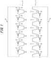
- FIG. 1 is a schematic diagram illustrating positions where compressive residual stress is specified in the present disclosure.
- a female thread portion 11 provided on the inner peripheral surface of at least one end of a metallic cylinder 10 has a plurality of thread grooves 12. The bottom of each thread groove 12 is a thread bottom 13 of the female thread portion.
- a male thread portion 21 configured to screw into the thread grooves 12 of the female thread portion 11 is provided on the outer peripheral surface of the lid 20, and has a plurality of thread ridges 22. Assuming the space between adjacent thread ridges 22 as a thread groove, the bottom of the thread groove is a thread bottom 23 of the male thread portion.
- FIG. 1 is merely a schematic diagram for explanation, and does not represent the actual shapes and dimensions of the thread portions.
- the tensile stress generated during use of the high pressure gas container spreads not only on the surface of the thread portion but also inside the material. Hence, the foregoing effect cannot be achieved if the residual compressive stress exists only in the surface layer of the thread portion. Accordingly, in the present disclosure, the maximum value of residual compressive stress at a position 0.4 mm in the depth direction from the thread bottom is 100 MPa or more.
- the maximum value of residual compressive stress is excessively high, the member constituting the metallic container buckles and the metallic container deforms.
- the maximum value of residual compressive stress is less than or equal to the tensile strength of the material of the metallic cylinder and less than or equal to the tensile strength of the material of the lid.
- the maximum value of residual compressive stress is more preferably less than or equal to the yield stress of the material of the metallic cylinder and less than or equal to the yield stress of the material of the lid, from the viewpoint of more reliably preventing buckling of the thread portion.
- the maximum value of residual compressive stress is the value in a state in which no internal pressure is applied to the metallic container.
- the maximum value of residual compressive stress may be obtained by elasto-plastic analysis by the finite element method (FEM).
- FEM finite element method
- the maximum value of residual compressive stress may be obtained by measuring the residual stress in a cross section of each of the male thread portion and the female thread portion by X-ray stress measurement.
- the material of the metallic cylinder is not limited, and may be any metal.
- the material is preferably low-alloy steel, from the viewpoint of cost reduction. It is particularly preferable to use, as the low-alloy steel, at least one of chromium molybdenum steel (JIS SCM steel), nickel chromium molybdenum steel (JIS SNCM steel), manganese chromium steel (JIS SMnC steel), manganese steel (JIS SMn steel), ASEM SA-723, and boron-added steel N28CB, N36CB, and N46CB.
- JIS SCM steel chromium molybdenum steel
- JIS SNCM steel nickel chromium molybdenum steel
- JIS SMnC steel manganese chromium steel
- ASEM SA-723 boron-added steel N28CB, N36CB, and N46CB.
- chromium molybdenum steel SA-723 steel, or nickel chromium molybdenum steel, with which quench hardenability can be easily ensured, is more preferable from the viewpoint of balancing with the material strength.
- chromium molybdenum steel (SCM435) contains C: 0.33 mass% to 0.38 mass%, Si: 0.15 mass% to 0.35 mass%, Mn: 0.60 mass% to 0.90 mass%, P: 0.030 mass% or less, S: 0.030 mass% or less, Cr: 0.90 mass% to 1.20 mass%, and Mo: 0.15 mass% to 0.30 mass%.
- the metallic cylinder a metallic cylinder produced by any method may be used.
- the container may be produced by hollowing out a steel material, or produced by working a steel pipe or tube.
- any steel pipe or tube such as an electric resistance welded steel pipe or tube or a seamless steel pipe or tube may be used.
- a metallic cylinder composed of a seamless steel pipe or tube is preferable.
- a metallic cylinder composed of a seamless steel pipe or tube not only has excellent properties such as toughness as compared with a metallic cylinder produced by hollowing but also has no weld portion, and thus is very suitable as a high pressure gas container.
- the female thread portion for screwing the lid is provided on the inner peripheral surface of at least one end of the metallic cylinder.
- the metallic cylinder has an opening for attaching the lid at at least one end, and the female thread portion is provided on the inner peripheral surface of the opening.
- the female thread portion is preferably provided at both ends of the metallic cylinder.
- the size of the opening is not limited. If the opening is excessively small, however, it is difficult to apply sufficient compressive residual stress to the thread portion by the below-described method. Accordingly, the ratio Di/Ds of the inner diameter Di of the metallic cylinder to the inner diameter Ds of the female thread portion in the metallic cylinder is preferably 3.5 or less, more preferably 2.0 or less, and further preferably 1.5 or less.
- the inner diameter Ds of the female thread portion is defined as the distance between the thread bottoms at opposite positions of the female thread portion formed on the inner peripheral surface of the metallic cylinder.
- the inner diameter Di of the metallic cylinder refers to the inner diameter of the metallic cylinder where the female thread portion is not formed, i.e. the inner diameter of the gas storage portion.
- Di/Ds is less than 0.8, the threads are excessively deep for the thickness of the metallic cylinder, so that the stress exerted on the thread bottom increases. Therefore, Di/Ds is preferably 0.8 or more and more preferably 0.9 or more, from the viewpoint of further reducing the stress exerted on the thread bottom.
- a carbon fiber reinforced resin layer may be provided on the surface of the metallic container. By providing the carbon fiber reinforced resin layer, the pressure resistance and fatigue resistance of the container can be further improved.
- Carbon fiber reinforced resin is a composite material obtained by impregnating carbon fiber as a reinforcing material with resin to improve the strength, and is called carbon-fiber-reinforced plastics (CFRP).
- CFRP carbon-fiber-reinforced plastics
- any carbon fiber such as PAN-based or pitch-based may be used, without being limited thereto.
- the volume content of the carbon fiber in the carbon fiber reinforced resin layer can be determined in accordance with Japanese Industrial Standard JIS K 7075 (1991). Usually, the volume content of the carbon fiber is preferably in the range of 50 % to 80 %.
- the carbon fiber reinforced resin layer can cover the whole or part of the outer surface of the metallic container.
- the high pressure gas container may have a structure (full-wrap) in which the whole outer surface of the metallic container is covered with the carbon fiber reinforced resin layer.
- the high pressure gas container preferably has a structure in which the carbon fiber reinforced resin layer is hoop-wrapped, i.e. a structure in which the carbon fiber is wound around the metallic container only in the circumferential direction.
- the outer peripheral surface of the metallic container is preferably subjected to treatment for prevention of electrolytic corrosion, such as coating by powder coating or winding of glass fiber reinforced resin (GFRP).
- GFRP glass fiber reinforced resin
- the metallic container can be prevented from rusting due to potential difference corrosion.
- thermoplastic powder paints based on vinyl chloride resin and the like and thermosetting powder paints based on polyester resin, acrylic resin, epoxy resin, etc. may be used. Given the heat generated when charging gas such as hydrogen, thermosetting powder paints are preferable.
- the lid of the metallic container is not limited, and may be any lid having, on the outer peripheral surface, a male thread portion configured to screw into the female thread portion of the metallic cylinder.
- the high pressure container according to the present disclosure includes a screw-type lid attachable to at least one end of the metallic cylinder.
- the lid may be a single-piece structure or a structure composed of a plurality of members.
- the lid preferably has a sealing member for sealing the high pressure gas in the container, on the outer peripheral surface.
- the sealing member is not limited, and may be any sealing member.
- An O-ring is preferably used as the sealing member. In the case where the lid includes an O-ring, the O-ring is preferably located on the container inner side relative to the male thread portion.
- the material of the lid is not limited, but is preferably metal, and more preferably steel.
- a steel material (low-alloy steel) having a tensile strength (TS) of 750 MPa or more is further preferable.
- the material of the lid may be the same as the foregoing material of the metallic cylinder.
- the material of the lid and the material of the metallic cylinder may be the same or different, but are preferably the same.
- the materials of the members may be selected independently or each other, and may be the same or different.
- the screw shape of the male thread portion of the lid is not limited, and may be, for example, a screw shape defined by JIS.
- the screw shape is preferably such a shape that reduces stress concentration.
- An example of the shape that reduces stress concentration is a screw with a large curvature radius at the tip of the thread bottom (e.g. a trapezoidal screw with a rounded tip).
- FIG. 2 is a schematic diagram illustrating the structure of a high pressure gas container 1 in one embodiment of the present disclosure.
- a cross section along a plane passing through the central axis of the high pressure gas container 1 is illustrated in the drawing.
- the high pressure gas container 1 includes a metallic cylinder 10, and the internal space of the metallic cylinder 10 forms a storage portion 14 for storing high pressure gas.
- a female thread portion 11 is provided on the inner peripheral surface of each of both ends of the metallic cylinder 10.
- a solid columnar lid 20 is provided at each of both ends of the metallic cylinder 10.
- a male thread portion 21 configured to screw into the female thread portion of the metallic cylinder 10 is provided on the outer peripheral surface of the lid 20.
- a lid of such a single-piece structure has the advantage that it can be produced easily.
- the lid 20 has an O-ring 24 as a sealing member on the outer peripheral surface.
- the male thread portion 21 is located on the container outer side relative to the O-ring 24 (i.e. on the side opposite to the storage portion 14).
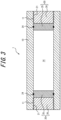
- FIG. 3 is a schematic sectional diagram illustrating the structure of a high pressure gas container 1 in another embodiment of the present disclosure. The description of the same parts as those in the embodiment illustrated in FIG. 2 is omitted here.
- the lid 20 in this embodiment is composed of a head plate 25 and a screw nut 26.
- the head plate 25 is a substantially plate-like (disk-shaped) member for sealing the gas in the container, and has an O-ring 24 as a sealing member on its peripheral surface instead of having a thread portion.
- the screw nut 26 is a solid columnar member, and has, on its outer peripheral surface, a male thread portion 21 configured to screw into the female thread portion of the metallic cylinder 10.
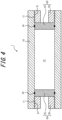
- FIG. 4 is a schematic sectional diagram illustrating the structure of a high pressure gas container 1 in another embodiment of the present disclosure. The description of the same parts as those in the embodiment illustrated in FIG. 3 is omitted here.
- the lid 20 in this embodiment is composed of a head plate 25 and a screw nut 26.
- the head plate 25 is a substantially plate-like (disk-shaped) member for sealing the gas in the container, and has an O-ring 24 as a sealing member on its peripheral surface instead of having a thread portion.
- the screw nut 26 is a hollow cylindrical member, and has, on its outer peripheral surface, a male thread portion 21 configured to screw into the female thread portion of the metallic cylinder 10.
- a lid of such a separated structure has the advantage that, when the male thread portion of the screw nut is damaged, only the screw nut needs to be replaced and the head plate does not need to be replaced, as in the embodiment illustrated in FIG. 4 .
- the screw nut 26 is hollow cylindrical, the weight of the lid can be considerably reduced, so that the weight of the high pressure gas container can be reduced.
- it is easier to apply stress to the thread bottom of the male thread portion than in the case where the screw nut 26 is a solid columnar member residual compressive stress can be applied to the thread bottom of the male thread portion without exerting excessive stress on the metallic cylinder.
- the hollow cylindrical screw nut 26 can be produced by any method.
- a steel material may be hollowed out to form a hollow cylinder, or a steel pipe or tube may be used.
- the steel pipe or tube any steel pipe or tube such as an electric resistance welded steel pipe or tube or a seamless steel pipe or tube may be used.
- a seamless steel pipe or tube is preferable.
- both the metallic cylinder 10 and the screw nut 26 are composed of seamless steel pipes or tubes, a common process can be used in part of the production processes for the metallic cylinder and the screw nut, which is very preferable from the viewpoint of productivity.
- the tensile strength of the member provided with the male thread portion from among the members constituting the lid is defined as the tensile strength of the material of the lid.
- the yield stress of the member provided with the male thread portion from among the members constituting the lid is defined as the yield stress of the material of the lid.
- the tensile strength and the yield stress of the material of the screw nut 26 are defined as the tensile strength and the yield stress of the material of the lid.
- the stress exerted on the thread portion when the metallic container is filled with gas can be alleviated.
- the stress reduction effect by the residual compressive stress varies depending on the force with which the lid is tightened.
- tightening the lid on the high pressure gas container is usually performed by applying a certain torque.
- tightening the lid causes stress to be exerted on the thread portion. If the stress exceeds the residual compressive stress applied beforehand, the residual compressive stress is offset. Therefore, in the case of tightening the lid on the high pressure gas container according to the present disclosure so that the male thread portion of the lid will screw into the female thread portion of the metallic cylinder, it is preferable to adjust the tightening torque so that the compressive residual stress applied beforehand will remain.
- the maximum value of residual compressive stress at a position of 0.4 mm in the depth direction from the plurality of thread bottoms of the female thread portion and male thread portion is more than 0.
- the male thread portion of the lid is screwed into the female thread portion of the metallic cylinder, and the maximum value of residual compressive stress at a position of 0.4 mm in the depth direction from the plurality of thread bottoms of the female thread portion and male thread portion is more than 0.
- a high pressure gas container assembly in one embodiment of the present disclosure is a high pressure gas container assembly comprising a metallic container, wherein the metallic container includes: a metallic cylinder having a female thread portion on an inner peripheral surface of at least one end; and a lid having, on an outer peripheral surface, a male thread portion configured to screw into the female thread portion, the male thread portion of the lid is screwed into the female thread portion of the metallic cylinder, and a maximum value of residual compressive stress at a position of 0.4 mm in a depth direction from a plurality of thread bottoms of the female thread portion and male thread portion is more than 0, less than or equal to tensile strength of a material of the metallic cylinder, and less than or equal to tensile strength of a material of the lid.
- the lid is preferably tightened with a torque of 10N ⁇ m or more, and more preferably tightened with a torque of 100N ⁇ m or more.
- a jig for preventing the lid from coming off to the high pressure gas container.
- a production method for a high pressure gas container in one embodiment of the present disclosure will be described below.
- internal pressure higher than the normal pressure of the high pressure gas container is applied to the high pressure gas container, excessive stress is generated and local plastic deformation occurs in the thread bottom. Since plastic deformation occurs only in one part and most of the other regions are elastic regions, compressive stress remains in the thread bottom after the internal pressure is removed.
- the predetermined residual compressive stress can be applied to the thread portion.
- a production method for a metallic container in one embodiment of the present disclosure comprises an internal pressure application process of applying an internal pressure to a metallic container under at least one of the following conditions (A) and (B) and under both of the following conditions (C) and (D). With this production method, a high pressure gas container having the predetermined residual compressive stress can be produced.
- the internal pressure is applied under at least one of the conditions (A) and (B) in the internal pressure application process.
- the condition (A) is satisfied, residual compressive stress can be applied to the female thread portion of the metallic cylinder.
- condition (B) is satisfied, residual compressive stress can be applied to the male thread portion of the lid.
- the thread bottom stress applied in the internal pressure application process is more than the tensile strength of the material.
- the thread bottom stress of the female thread portion and the thread bottom stress of the male thread portion in the internal pressure application process is adjusted so as to apply the desired residual compressive stress.
- the stress on the outer surface of the metallic cylinder (the outer peripheral surface of the cylinder) facing the female thread portion is preferably less than or equal to the yield stress of the material of the metallic cylinder in the internal pressure application process.
- the residual compressive stress can be applied to the vicinity of the thread bottom more effectively than in the case where stress higher than the yield stress is applied to the metallic cylinder throughout its thickness.
- the stress on the inner surface of the screw nut (the inner peripheral surface of the cylindrical nut) facing the male thread portion is preferably less than or equal to the yield stress of the material of the screw nut in the internal pressure application process.
- Axial stress pressure receiving area of lid ⁇ internal pressure / minimum cross-sectional area of metallic cylinder
- Circumferential stress inner diameter of metallic cylinder ⁇ internal pressure / 2 ⁇ thickness of metallic cylinder
- the "pressure-receiving area of lid” is the area of the surface of the lid in contact with the storage portion.
- the "pressure-receiving area of lid” is the area of the head plate.
- the "cross-sectional area of metallic cylinder” is the cross-sectional area of the metal part in a cross section perpendicular to the axial direction of the metallic cylinder, and does not include the cross-sectional area of the internal space of the metallic cylinder.
- the cross-sectional area of the metallic cylinder may vary depending on the position in the longitudinal direction of the metallic cylinder, and the axial stress exerted on the metallic cylinder is maximum in the part where the cross-sectional area is minimum.
- the minimum cross-sectional area of the metallic cylinder is used in the formula (1).
- the axial stress and the circumferential stress calculated respectively using the formulas (1) and (2) are each average stress per cross-sectional area of the metallic cylinder.
- the thread bottom stress which is local stress can be calculated by, for example, the finite element method as described later.
- the axial stress and the circumferential stress exerted on the metallic cylinder are lower than the values calculated according to the formulas (1) and (2) respectively.
- the axial stress and the circumferential stress exerted on the metallic cylinder are evaluated by numerical analysis using the finite element method.
- the axial stress and the circumferential stress exerted on the metallic cylinder are preferably less than or equal to the yield stress of the material of the metallic cylinder, and more preferably less than or equal to 90 % of the yield stress.
- the metallic container is filled with any pressure medium.
- the pressure medium is not limited, and may be any medium.
- an incompressible fluid such as water or oil is preferable.
- an incompressible fluid containing a corrosion inhibitor or an aqueous solution of alcohol such as ethylene glycol is preferable.
- a production method for a metallic container in another embodiment of the present disclosure is a production method for a high pressure gas container, comprising: attaching a jig having a male thread portion on an outer peripheral surface to a metallic cylinder so that the male thread portion of the jig will screw into a female thread portion of the metallic cylinder; applying an internal pressure to the metallic container under the following conditions (A), (C), and (D):
- a jig having a male thread portion on the outer peripheral surface is attached to a metallic cylinder so that the male thread portion of the jig will screw into the female thread portion of the metallic cylinder (jig attachment process).
- the jig may be any jig having the male thread portion configured to screw into the female thread portion of the metallic cylinder.
- the same member used as the lid of the metallic container is preferably used. More preferably, the lid used as the jig is subsequently used again as the lid in the below-described lid tightening process.
- the material of the jig is not limited, but is preferably metal, and more preferably steel.
- a steel material (low-alloy steel) having a tensile strength (TS) of 750 MPa or more is further preferable.
- the material of the jig may be the same as the foregoing material of the metallic cylinder.
- the material of the jig and the material of the metallic cylinder may be the same or different, but are preferably the same.
- an internal pressure is applied to the metallic container under the following conditions (A), (C), and (D) (internal pressure application process).
- the reasons for limiting the conditions (A), (C), and (D) are as described in the foregoing Embodiment 1.
- the other points are the same as those in Embodiment 1 unless otherwise specified.
- the jig is removed from the metallic container (jig removal process).
- the lid is tightened on the metallic cylinder so that the male thread portion of the lid will screw into the female thread portion of the metallic cylinder (lid tightening process).
- the tightening torque is adjusted so that the maximum value of residual compressive stress at a position of 0.4 mm in the depth direction from the plurality of thread bottoms of the female thread portion and male thread portion will be more than 0.
- the lid As mentioned above, it is preferable to use the lid as the jig in the jig attachment process and again use, in the lid tightening process, the lid which was used in the jig attachment process.
- the lid includes a sealing member such as an O-ring
- the sealing member of the lid is replaced before tightening the lid.
- the diameter of the sealing member used in the internal pressure application process is preferably larger than the diameter of the sealing member used in the final lid tightening process.
- the thread bottom stress was analyzed by elasto-plastic analysis by the finite element method (FEM) using container models.
- FEM finite element method
- the container models the following two types of models were used: a Type 1 container composed of a metallic container made of low-alloy steel and having no carbon fiber reinforced resin layer; and a Type 2 container composed of a metallic container (liner) made of low-alloy steel same as the Type 1 container and a carbon fiber reinforced resin layer formed by winding CFRP on the surface of the metallic container so as to have a thickness of 5 mm.
- the metallic cylinder and the lid forming the metallic container were made of the same low-alloy steel.
- the tensile strength (TS) of the low-alloy steel was 821 MPa, and the yield stress (YP ) of the low-alloy steel was 705 MPa.
- the stress-strain curve of the low-alloy steel the stress-strain curve of TS: 900 MPa class SNCM439 steel was used.
- the lid had a structure including a disk-shaped head plate and a hollow cylindrical screw nut, as illustrated in FIG. 4 .
- the thickness of the head plate was 75 mm
- the thickness of the screw nut was 37 mm.
- the thickness of the screw nut is the thickness from the apex of the thread portion provided on the outer peripheral surface to the inner surface.
- the screw shape was a JIS trapezoidal screw with a pitch of 12 mm, a thread depth of 12 mm, and a thread shoulder curvature radius of 2.2 mm.
- the thread bottom stress when the load internal pressure shown in Table 1 was applied to the metallic container was obtained by FEM.
- the maximum value of the thread bottom stress in the female thread portion and the maximum value of the thread bottom stress in the male thread portion are shown in Table 1.
- the maximum value of the thread bottom stress refers to the maximum value of the stress throughout the thickness from the thread bottom to the surface on the side opposite to the thread bottom.
- the maximum value of the thread bottom stress of the male thread portion in the internal pressure application process was lower than the maximum value of the thread bottom stress of the female thread portion in all cases shown in Table 1. Accordingly, only the maximum value of the thread bottom stress of the female thread portion is shown in Table 1.
- the axial stress and the circumferential stress of the metallic cylinder when the load internal pressure was applied are also shown in Table 1.
- the axial stress and the circumferential stress were calculated according to the following formulas (1) and (2):
- Axial stress pressure receiving area of lid ⁇ internal pressure / minimum cross-sectional area of metallic cylinder
- Circumferential stress inner diameter of metallic cylinder ⁇ internal pressure / 2 ⁇ thickness of metallic cylinder
- the axial stress and the circumferential stress were obtained by FEM analysis.
- the fracture life of the thread portion in the pressure cycle test was evaluated.
- the fracture life was evaluated according to the "Crack Growth Analysis Method for Various Sites" (KHKS 0220 (2010) Annex IX) stipulated by the High Pressure Gas Safety Institute of Japan.
- the pressure application conditions were as follows: minimum pressure: 2 MPa, maximum pressure: 82 MPa, and temperature: room temperature.
Landscapes
- Engineering & Computer Science (AREA)
- General Engineering & Computer Science (AREA)
- Mechanical Engineering (AREA)
- Filling Or Discharging Of Gas Storage Vessels (AREA)
Applications Claiming Priority (2)
| Application Number | Priority Date | Filing Date | Title |
|---|---|---|---|
| JP2020187525 | 2020-11-10 | ||
| PCT/JP2021/040464 WO2022102478A1 (ja) | 2020-11-10 | 2021-11-02 | 高圧ガス用容器およびその製造方法 |
Publications (3)
| Publication Number | Publication Date |
|---|---|
| EP4246019A1 true EP4246019A1 (de) | 2023-09-20 |
| EP4246019A4 EP4246019A4 (de) | 2024-05-08 |
| EP4246019B1 EP4246019B1 (de) | 2025-12-31 |
Family
ID=81601211
Family Applications (1)
| Application Number | Title | Priority Date | Filing Date |
|---|---|---|---|
| EP21891724.3A Active EP4246019B1 (de) | 2020-11-10 | 2021-11-02 | Hochdruckgasbehälter und verfahren zur herstellung davon |
Country Status (6)
| Country | Link |
|---|---|
| US (1) | US12429167B2 (de) |
| EP (1) | EP4246019B1 (de) |
| JP (1) | JP7757138B2 (de) |
| KR (1) | KR102828675B1 (de) |
| CN (1) | CN116529509A (de) |
| WO (1) | WO2022102478A1 (de) |
Families Citing this family (2)
| Publication number | Priority date | Publication date | Assignee | Title |
|---|---|---|---|---|
| DE102023106062A1 (de) * | 2023-03-10 | 2024-09-12 | Bauer Kompressoren Gmbh | Geschraubter Druckbehälter |
| WO2025033061A1 (ja) * | 2023-08-04 | 2025-02-13 | Agc株式会社 | 充填容器及びその保管方法 |
Family Cites Families (18)
| Publication number | Priority date | Publication date | Assignee | Title |
|---|---|---|---|---|
| JP4164995B2 (ja) | 2000-07-19 | 2008-10-15 | いすゞ自動車株式会社 | 機械構造用合金鋼の表面改質方法及び表面改質材 |
| JP2004052857A (ja) * | 2002-07-18 | 2004-02-19 | Mitsubishi Heavy Ind Ltd | 均等荷重型ねじ蓋式高圧容器 |
| JP2006144934A (ja) | 2004-11-19 | 2006-06-08 | Toyoda Mach Works Ltd | 動力伝達シャフト |
| JP5178235B2 (ja) | 2008-02-22 | 2013-04-10 | 東芝プラントシステム株式会社 | ネジ穴を有する金属部品のピーニング方法および装置 |
| JP6096136B2 (ja) | 2014-02-24 | 2017-03-15 | 株式会社日本製鋼所 | 水素ガス蓄圧器 |
| JP6388524B2 (ja) * | 2014-10-31 | 2018-09-12 | Jfeコンテイナー株式会社 | 蓄圧器及び蓄圧器の製造方法 |
| JP6454635B2 (ja) | 2015-12-01 | 2019-01-16 | 株式会社神戸製鋼所 | 耐遅れ破壊性および疲労特性に優れた高強度ボルト、およびその製造方法 |
| JP6781892B2 (ja) | 2016-02-12 | 2020-11-11 | 株式会社日本製鋼所 | 蓄圧容器 |
| JP6425689B2 (ja) * | 2016-07-15 | 2018-11-21 | 株式会社日本製鋼所 | 水素用圧力容器およびその製造方法 |
| JP6975695B2 (ja) * | 2017-09-04 | 2021-12-01 | Jfeスチール株式会社 | 高圧水素ガス用蓄圧器 |
| JP6882237B2 (ja) | 2017-09-04 | 2021-06-02 | Jfeスチール株式会社 | 高圧水素ガス用蓄圧器 |
| JP7479622B2 (ja) | 2017-10-27 | 2024-05-09 | 日本製鋼所M&E株式会社 | 蓄圧容器 |
| JP6725485B2 (ja) * | 2017-12-25 | 2020-07-22 | Jfeスチール株式会社 | 高圧水素ガス用蓄圧器 |
| KR102134769B1 (ko) * | 2018-05-09 | 2020-07-16 | 일성기계공업 주식회사 | 공기 배출이 용이한 고압가스용기용 캡 |
| JP7155644B2 (ja) * | 2018-06-18 | 2022-10-19 | 日本製鉄株式会社 | ボルト |
| JP7100553B2 (ja) * | 2018-10-02 | 2022-07-13 | 日本製鋼所M&E株式会社 | 水素蓄圧器 |
| JP7270203B2 (ja) * | 2018-10-17 | 2023-05-10 | 日本製鋼所M&E株式会社 | ガス蓄圧器 |
| JP6757046B1 (ja) * | 2019-07-17 | 2020-09-16 | 日星機械工業株式會社 | 高圧ガス貯蔵用圧力容器 |
-
2021
- 2021-11-02 JP JP2021179843A patent/JP7757138B2/ja active Active
- 2021-11-02 US US18/250,536 patent/US12429167B2/en active Active
- 2021-11-02 CN CN202180074969.1A patent/CN116529509A/zh active Pending
- 2021-11-02 KR KR1020237015585A patent/KR102828675B1/ko active Active
- 2021-11-02 EP EP21891724.3A patent/EP4246019B1/de active Active
- 2021-11-02 WO PCT/JP2021/040464 patent/WO2022102478A1/ja not_active Ceased
Also Published As
| Publication number | Publication date |
|---|---|
| JP2022077008A (ja) | 2022-05-20 |
| CN116529509A (zh) | 2023-08-01 |
| US12429167B2 (en) | 2025-09-30 |
| EP4246019A4 (de) | 2024-05-08 |
| US20240003491A1 (en) | 2024-01-04 |
| JP7757138B2 (ja) | 2025-10-21 |
| KR20230084262A (ko) | 2023-06-12 |
| KR102828675B1 (ko) | 2025-07-02 |
| WO2022102478A1 (ja) | 2022-05-19 |
| EP4246019B1 (de) | 2025-12-31 |
Similar Documents
| Publication | Publication Date | Title |
|---|---|---|
| EP2990714B1 (de) | Akkumulator | |
| EP4246019B1 (de) | Hochdruckgasbehälter und verfahren zur herstellung davon | |
| CN103761365B (zh) | 一种基于寿命的高温压力容器蠕变疲劳强度设计方法 | |
| EP3702660B1 (de) | Druckbehälter | |
| US7818986B1 (en) | Multiple autofrettage | |
| JP6725485B2 (ja) | 高圧水素ガス用蓄圧器 | |
| EP3425259A1 (de) | Druckbehälter und umwicklungverbunddruckbehälter | |
| JP7530879B2 (ja) | 高圧水素ガス用蓄圧器 | |
| EP4246020B1 (de) | Stahlrohr mit gewinde und verfahren zur herstellung davon | |
| JP6882237B2 (ja) | 高圧水素ガス用蓄圧器 | |
| JP2019044890A (ja) | 高圧水素ガス用蓄圧器およびその製造方法 | |
| JP6774465B2 (ja) | 高圧水素ガス用蓄圧器の蓋構造および高圧水素ガス用蓄圧器 | |
| US20030146229A1 (en) | Pressure vessels for high pressure applications | |
| Shinkin | Influence of non-linearity of hardening curve on elasticoplastic bend of rectangular rod | |
| US10518312B1 (en) | Products manufactured by autofrettage | |
| Peters et al. | Advances and Challenges in Powder Metal Hip Processing for the Production of Large Components | |
| RU193002U1 (ru) | Баллон для хранения сжатого натурального газа | |
| Liu et al. | Study on Anti-Instability Inflation Pressure of Vehicle-Mounted Type Ⅳ Hydrogen Storage Cylinder | |
| Kihiu et al. | Overstrain in flush optimal-chamfered cross-bored cylinders | |
| Koh | Residual Stress Evaluation and Its Effects on the Fatigue Life of an Autofrettaged Tube |
Legal Events
| Date | Code | Title | Description |
|---|---|---|---|
| STAA | Information on the status of an ep patent application or granted ep patent |
Free format text: STATUS: THE INTERNATIONAL PUBLICATION HAS BEEN MADE |
|
| PUAI | Public reference made under article 153(3) epc to a published international application that has entered the european phase |
Free format text: ORIGINAL CODE: 0009012 |
|
| STAA | Information on the status of an ep patent application or granted ep patent |
Free format text: STATUS: REQUEST FOR EXAMINATION WAS MADE |
|
| 17P | Request for examination filed |
Effective date: 20230331 |
|
| AK | Designated contracting states |
Kind code of ref document: A1 Designated state(s): AL AT BE BG CH CY CZ DE DK EE ES FI FR GB GR HR HU IE IS IT LI LT LU LV MC MK MT NL NO PL PT RO RS SE SI SK SM TR |
|
| DAV | Request for validation of the european patent (deleted) | ||
| DAX | Request for extension of the european patent (deleted) | ||
| A4 | Supplementary search report drawn up and despatched |
Effective date: 20240410 |
|
| RIC1 | Information provided on ipc code assigned before grant |
Ipc: F17C 1/00 20060101ALI20240404BHEP Ipc: F16J 12/00 20060101AFI20240404BHEP |
|
| REG | Reference to a national code |
Ref country code: DE Ref legal event code: R079 Free format text: PREVIOUS MAIN CLASS: F16J0012000000 Ipc: F17C0013060000 Ref document number: 602021045727 Country of ref document: DE |
|
| GRAP | Despatch of communication of intention to grant a patent |
Free format text: ORIGINAL CODE: EPIDOSNIGR1 |
|
| STAA | Information on the status of an ep patent application or granted ep patent |
Free format text: STATUS: GRANT OF PATENT IS INTENDED |
|
| RIC1 | Information provided on ipc code assigned before grant |
Ipc: F17C 13/06 20060101AFI20250521BHEP |
|
| INTG | Intention to grant announced |
Effective date: 20250603 |
|
| GRAJ | Information related to disapproval of communication of intention to grant by the applicant or resumption of examination proceedings by the epo deleted |
Free format text: ORIGINAL CODE: EPIDOSDIGR1 |
|
| STAA | Information on the status of an ep patent application or granted ep patent |
Free format text: STATUS: REQUEST FOR EXAMINATION WAS MADE |
|
| INTC | Intention to grant announced (deleted) | ||
| GRAP | Despatch of communication of intention to grant a patent |
Free format text: ORIGINAL CODE: EPIDOSNIGR1 |
|
| STAA | Information on the status of an ep patent application or granted ep patent |
Free format text: STATUS: GRANT OF PATENT IS INTENDED |
|
| INTG | Intention to grant announced |
Effective date: 20250917 |
|
| GRAS | Grant fee paid |
Free format text: ORIGINAL CODE: EPIDOSNIGR3 |
|
| GRAA | (expected) grant |
Free format text: ORIGINAL CODE: 0009210 |
|
| STAA | Information on the status of an ep patent application or granted ep patent |
Free format text: STATUS: THE PATENT HAS BEEN GRANTED |
|
| AK | Designated contracting states |
Kind code of ref document: B1 Designated state(s): AL AT BE BG CH CY CZ DE DK EE ES FI FR GB GR HR HU IE IS IT LI LT LU LV MC MK MT NL NO PL PT RO RS SE SI SK SM TR |
|
| REG | Reference to a national code |
Ref country code: CH Ref legal event code: F10 Free format text: ST27 STATUS EVENT CODE: U-0-0-F10-F00 (AS PROVIDED BY THE NATIONAL OFFICE) Effective date: 20251231 Ref country code: GB Ref legal event code: FG4D |
|
| REG | Reference to a national code |
Ref country code: DE Ref legal event code: R096 Ref document number: 602021045727 Country of ref document: DE |
|
| REG | Reference to a national code |
Ref country code: IE Ref legal event code: FG4D |
|
| REG | Reference to a national code |
Ref country code: LT Ref legal event code: MG9D |
|
| PG25 | Lapsed in a contracting state [announced via postgrant information from national office to epo] |
Ref country code: NO Free format text: LAPSE BECAUSE OF FAILURE TO SUBMIT A TRANSLATION OF THE DESCRIPTION OR TO PAY THE FEE WITHIN THE PRESCRIBED TIME-LIMIT Effective date: 20260331 |
|
| PG25 | Lapsed in a contracting state [announced via postgrant information from national office to epo] |
Ref country code: FI Free format text: LAPSE BECAUSE OF FAILURE TO SUBMIT A TRANSLATION OF THE DESCRIPTION OR TO PAY THE FEE WITHIN THE PRESCRIBED TIME-LIMIT Effective date: 20251231 Ref country code: HR Free format text: LAPSE BECAUSE OF FAILURE TO SUBMIT A TRANSLATION OF THE DESCRIPTION OR TO PAY THE FEE WITHIN THE PRESCRIBED TIME-LIMIT Effective date: 20251231 |
|
| PG25 | Lapsed in a contracting state [announced via postgrant information from national office to epo] |
Ref country code: RS Free format text: LAPSE BECAUSE OF FAILURE TO SUBMIT A TRANSLATION OF THE DESCRIPTION OR TO PAY THE FEE WITHIN THE PRESCRIBED TIME-LIMIT Effective date: 20260331 |
|
| PG25 | Lapsed in a contracting state [announced via postgrant information from national office to epo] |
Ref country code: LV Free format text: LAPSE BECAUSE OF FAILURE TO SUBMIT A TRANSLATION OF THE DESCRIPTION OR TO PAY THE FEE WITHIN THE PRESCRIBED TIME-LIMIT Effective date: 20251231 |