EP4246049A1 - Diffusions-deckenlüftungssystem - Google Patents
Diffusions-deckenlüftungssystem Download PDFInfo
- Publication number
- EP4246049A1 EP4246049A1 EP22161852.3A EP22161852A EP4246049A1 EP 4246049 A1 EP4246049 A1 EP 4246049A1 EP 22161852 A EP22161852 A EP 22161852A EP 4246049 A1 EP4246049 A1 EP 4246049A1
- Authority
- EP
- European Patent Office
- Prior art keywords
- ceiling
- air
- profiles
- diffuse
- ventilation system
- Prior art date
- Legal status (The legal status is an assumption and is not a legal conclusion. Google has not performed a legal analysis and makes no representation as to the accuracy of the status listed.)
- Pending
Links
Images

Classifications
-
- F—MECHANICAL ENGINEERING; LIGHTING; HEATING; WEAPONS; BLASTING
- F24—HEATING; RANGES; VENTILATING
- F24F—AIR-CONDITIONING; AIR-HUMIDIFICATION; VENTILATION; USE OF AIR CURRENTS FOR SCREENING
- F24F7/00—Ventilation
- F24F7/04—Ventilation with ducting systems, e.g. by double walls; with natural circulation
- F24F7/06—Ventilation with ducting systems, e.g. by double walls; with natural circulation with forced air circulation, e.g. by fan positioning of a ventilator in or against a conduit
- F24F7/10—Ventilation with ducting systems, e.g. by double walls; with natural circulation with forced air circulation, e.g. by fan positioning of a ventilator in or against a conduit with air supply, or exhaust, through perforated wall, floor or ceiling
-
- E—FIXED CONSTRUCTIONS
- E04—BUILDING
- E04B—GENERAL BUILDING CONSTRUCTIONS; WALLS, e.g. PARTITIONS; ROOFS; FLOORS; CEILINGS; INSULATION OR OTHER PROTECTION OF BUILDINGS
- E04B9/00—Ceilings; Construction of ceilings, e.g. false ceilings; Ceiling construction with regard to insulation
- E04B9/02—Ceilings; Construction of ceilings, e.g. false ceilings; Ceiling construction with regard to insulation having means for ventilation or vapour discharge
-
- E—FIXED CONSTRUCTIONS
- E04—BUILDING
- E04B—GENERAL BUILDING CONSTRUCTIONS; WALLS, e.g. PARTITIONS; ROOFS; FLOORS; CEILINGS; INSULATION OR OTHER PROTECTION OF BUILDINGS
- E04B9/00—Ceilings; Construction of ceilings, e.g. false ceilings; Ceiling construction with regard to insulation
- E04B9/06—Ceilings; Construction of ceilings, e.g. false ceilings; Ceiling construction with regard to insulation characterised by constructional features of the supporting construction, e.g. cross section or material of framework members
-
- E—FIXED CONSTRUCTIONS
- E04—BUILDING
- E04B—GENERAL BUILDING CONSTRUCTIONS; WALLS, e.g. PARTITIONS; ROOFS; FLOORS; CEILINGS; INSULATION OR OTHER PROTECTION OF BUILDINGS
- E04B9/00—Ceilings; Construction of ceilings, e.g. false ceilings; Ceiling construction with regard to insulation
- E04B9/06—Ceilings; Construction of ceilings, e.g. false ceilings; Ceiling construction with regard to insulation characterised by constructional features of the supporting construction, e.g. cross section or material of framework members
- E04B9/065—Ceilings; Construction of ceilings, e.g. false ceilings; Ceiling construction with regard to insulation characterised by constructional features of the supporting construction, e.g. cross section or material of framework members comprising supporting beams having a folded cross-section
- E04B9/067—Ceilings; Construction of ceilings, e.g. false ceilings; Ceiling construction with regard to insulation characterised by constructional features of the supporting construction, e.g. cross section or material of framework members comprising supporting beams having a folded cross-section with inverted T-shaped cross-section
-
- E—FIXED CONSTRUCTIONS
- E04—BUILDING
- E04B—GENERAL BUILDING CONSTRUCTIONS; WALLS, e.g. PARTITIONS; ROOFS; FLOORS; CEILINGS; INSULATION OR OTHER PROTECTION OF BUILDINGS
- E04B9/00—Ceilings; Construction of ceilings, e.g. false ceilings; Ceiling construction with regard to insulation
- E04B9/22—Connection of slabs, panels, sheets or the like to the supporting construction
- E04B9/24—Connection of slabs, panels, sheets or the like to the supporting construction with the slabs, panels, sheets or the like positioned on the upperside of, or held against the underside of the horizontal flanges of the supporting construction or accessory means connected thereto
- E04B9/241—Connection of slabs, panels, sheets or the like to the supporting construction with the slabs, panels, sheets or the like positioned on the upperside of, or held against the underside of the horizontal flanges of the supporting construction or accessory means connected thereto with the slabs, panels, sheets or the like positioned on the upperside of the horizontal flanges of the supporting construction
-
- E—FIXED CONSTRUCTIONS
- E04—BUILDING
- E04B—GENERAL BUILDING CONSTRUCTIONS; WALLS, e.g. PARTITIONS; ROOFS; FLOORS; CEILINGS; INSULATION OR OTHER PROTECTION OF BUILDINGS
- E04B9/00—Ceilings; Construction of ceilings, e.g. false ceilings; Ceiling construction with regard to insulation
- E04B9/34—Grid-like or open-work ceilings, e.g. lattice type box-like modules, acoustic baffles
-
- F—MECHANICAL ENGINEERING; LIGHTING; HEATING; WEAPONS; BLASTING
- F24—HEATING; RANGES; VENTILATING
- F24F—AIR-CONDITIONING; AIR-HUMIDIFICATION; VENTILATION; USE OF AIR CURRENTS FOR SCREENING
- F24F11/00—Control or safety arrangements
- F24F11/70—Control systems characterised by their outputs; Constructional details thereof
- F24F11/72—Control systems characterised by their outputs; Constructional details thereof for controlling the supply of treated air, e.g. its pressure
- F24F11/74—Control systems characterised by their outputs; Constructional details thereof for controlling the supply of treated air, e.g. its pressure for controlling air flow rate or air velocity
-
- F—MECHANICAL ENGINEERING; LIGHTING; HEATING; WEAPONS; BLASTING
- F24—HEATING; RANGES; VENTILATING
- F24F—AIR-CONDITIONING; AIR-HUMIDIFICATION; VENTILATION; USE OF AIR CURRENTS FOR SCREENING
- F24F13/00—Details common to, or for air-conditioning, air-humidification, ventilation or use of air currents for screening
- F24F13/02—Ducting arrangements
- F24F13/06—Outlets for directing or distributing air into rooms or spaces, e.g. ceiling air diffuser
- F24F13/068—Outlets for directing or distributing air into rooms or spaces, e.g. ceiling air diffuser formed as perforated walls, ceilings or floors
-
- F—MECHANICAL ENGINEERING; LIGHTING; HEATING; WEAPONS; BLASTING
- F24—HEATING; RANGES; VENTILATING
- F24F—AIR-CONDITIONING; AIR-HUMIDIFICATION; VENTILATION; USE OF AIR CURRENTS FOR SCREENING
- F24F13/00—Details common to, or for air-conditioning, air-humidification, ventilation or use of air currents for screening
- F24F13/02—Ducting arrangements
- F24F13/06—Outlets for directing or distributing air into rooms or spaces, e.g. ceiling air diffuser
- F24F13/072—Outlets for directing or distributing air into rooms or spaces, e.g. ceiling air diffuser of elongated shape, e.g. between ceiling panels
-
- F—MECHANICAL ENGINEERING; LIGHTING; HEATING; WEAPONS; BLASTING
- F24—HEATING; RANGES; VENTILATING
- F24F—AIR-CONDITIONING; AIR-HUMIDIFICATION; VENTILATION; USE OF AIR CURRENTS FOR SCREENING
- F24F13/00—Details common to, or for air-conditioning, air-humidification, ventilation or use of air currents for screening
- F24F13/08—Air-flow control members, e.g. louvres, grilles, flaps or guide plates
-
- E—FIXED CONSTRUCTIONS
- E04—BUILDING
- E04B—GENERAL BUILDING CONSTRUCTIONS; WALLS, e.g. PARTITIONS; ROOFS; FLOORS; CEILINGS; INSULATION OR OTHER PROTECTION OF BUILDINGS
- E04B9/00—Ceilings; Construction of ceilings, e.g. false ceilings; Ceiling construction with regard to insulation
- E04B9/02—Ceilings; Construction of ceilings, e.g. false ceilings; Ceiling construction with regard to insulation having means for ventilation or vapour discharge
- E04B2009/026—Ceilings; Construction of ceilings, e.g. false ceilings; Ceiling construction with regard to insulation having means for ventilation or vapour discharge the supporting ceiling grid acting as air diffusers
Definitions
- the present invention relates to a diffuse ceiling ventilation system, and more specifically to a diffuse ceiling ventilation system comprising a plurality of ceiling tiles and a grid of profiles for supporting the ceiling tiles.
- Suspended ceilings are common in modern buildings today, and commonly comprises a grid of profiles supporting a plurality of ceiling tiles.
- a suspended ceiling may cover building infrastructure such as pipes and cables in a plenum space above the suspended ceiling.
- a suspended ceiling may further be provided to improve the acoustics of a room below.
- a suspended ceiling may be part of a ceiling ventilation system, for providing fresh air to the room.
- Diffuse ceiling ventilation systems is one such system for providing air to a room below a suspended ceiling.
- Diffuse ceiling ventilation systems may be provided in large rooms, and may even be provided across entire floors of a building.
- An air inlet may be provided above the suspended ceiling, and the suspended ceiling allows a flow of air to enter the room below.
- a diffuse ceiling ventilation system do not provide air from the air inlet to the room below through a few main entry points, but instead flows air from the air inlet across the suspended ceiling and creates a diffuse flow of air into the room through a plurality of air gaps distributed throughout the suspended ceiling.
- an object of the present invention is to provide a diffuse ceiling ventilation system that distributes air from an air inlet in a controlled manner through a suspended ceiling into a room.
- Another object is to provide a diffuse ceiling ventilation system comprising air gaps with an increased air flow area.
- Another object is to provide a diffuse ceiling ventilation system comprising ceiling tiles with planar lower surfaces.
- a diffuse ceiling ventilation system for a flow of air from a plenum space into a room below a suspended ceiling.
- the diffuse ceiling ventilation system comprising an air inlet for providing air to the plenum space.
- the suspended ceiling comprising a plurality of ceiling tiles and a grid of profiles for supporting the plurality of ceiling tiles.
- the grid of profiles and/or the ceiling tiles are configured to form air gaps allowing air to flow from the plenum space to the room below.
- the air gaps are configured to have an increased air flow area as a function of increased distance from the air inlet for providing a controlled flow of air through the suspended ceiling into the room below.
- the profiles and/or the ceiling tiles of the diffuse ceiling ventilation system may be manufactured at a large scale in various configurations, and the various profiles and/or ceiling tiles may advantageously be combined on site to form a diffuse ceiling ventilation system with air gaps configured to have an increased air flow area as a function of increased distance from the air inlet.
- the diffuse ceiling ventilation system allows the air flow through a suspended ceiling to be accurately calibrated for various flow rates from air inlets, and various areas of suspended ceilings.
- a ceiling tile and/or associated profiles are configured to form the air gaps with an air flow area that may vary from one ceiling tile and associated profiles to an adjacent ceiling tile and associated profiles, to control the flow of air past each ceiling tile and associated profiles.
- the profiles comprise flanges and a ceiling tile rests on at least two associated flanges'.
- the air gaps comprise openings in the profiles, and the openings are configured to increase in number and/or size as the distance from the air inlet increases.
- the air gaps are provided on flanges of the profiles.
- each flange comprises a ridge and the openings are provided on the ridges.
- the air gaps comprise openings formed by ceiling tiles spaced apart from the profiles by spacer elements, the spacer elements are configured to increase in height from one ceiling tile to another ceiling tile as the distance from the at least one air inlet increases.
- the spacer elements are provided along a periphery of the ceiling tiles.
- the spacer elements are provided in stepped notches of the ceiling tiles.
- the height of the stepped notches is configured to increase correspondingly to the height of the spacer elements, so as to provide planar lower surfaces of the plurality of ceiling tiles.
- a ceiling tile rests on two associated profiles and the air gaps comprise gaps formed between adjacent ceiling tiles.
- the air gaps comprise openings formed by ceiling tiles spaced apart from the profiles by solid spacer elements, the distance between the solid spacer elements of a ceiling tile is configured to increase from one ceiling tile to another ceiling tile as the distance from the at least one air inlet increases.
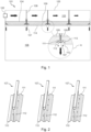
- Figure 1 comprises a circled area A that shows a detailed view of a portion of figure 1 .
- the diffuse ceiling ventilation system 101 comprises an air inlet 102.
- the air inlet 102 may be an opening, a vent or any such air intake for providing fresh air from an outside or from a ventilating system to a plenum space 103.
- a flow of air is thus provided from the air inlet 102 to the plenum space 103.
- a diffuse ventilation system 101 may as such comprise more than one air inlet 102, and the plurality of air inlets 102 may be positioned at various locations. A distance from an air inlet 102 is thus the distance from the nearest air inlet 102.
- the plenum space 103 is the space above a suspended ceiling 104 and below a ceiling 105 in e.g. a building.
- a room 106 is situated below the suspended ceiling 104.
- the air from the air inlet 102 flows at a rate that may vary depending on the conditions in the room 106, the volume of the plenum space 103 or room 106, the capacity of the ventilation system, etc.
- the air flow from the air inlet 102 is in figure 1 illustrated with horizontal arrows from the air inlet 102 towards the right, but the air will flow in several directions originating from the air inlet 102.
- the horizontal arrows in figure 1 decrease in size as the distance to the air inlet 102 increases, illustrating the decrease in air flow with the distance from the air inlet 102.
- the suspended ceiling 104 comprises a grid of profiles 107.
- the grid of profiles 107 may comprise longitudinal and latitudinal profiles 107.
- the profiles 107 may be suspended from the ceiling 105 by suspending elements 108.
- the suspending elements 108 may be wires, bars or profiles that support the profiles 107 in a vertical direction, and the height of the suspending elements 108 may be adjusted depending on the height of the plenum space 103.
- the profiles 107 support a plurality of ceiling tiles 109. In figure 1 , four ceiling tiles 109 are shown. Ceiling tiles are known in the art and may or may not be air permeable. The air permeability of a ceiling tile may be insufficient to provide a flow of air to the room 106.
- a profile 107 may comprise at least one flange 110 for supporting the ceiling tiles 109.
- a flange 110 may protrude on each side of a profile 107, and a profile 107 may preferably comprise two flanges 110, one flange 110 arranged on each side in a horizontal, longitudinal direction of the profile 107.
- a flange 110 may comprise a ridge 111 for supporting the ceiling tile 109.
- the ridge 111 may be one or more raised portion(s) or a longitudinal elevation of the flange 110. The ridge 111 thus elevates a ceiling tile 109 from the flange 110.
- the ridge 111 may comprise air gaps 112 for allowing a flow of air through the suspended ceiling 104.
- the air gaps 112 may be provided on the sides of the ridges 111, for allowing a flow of air through the air gaps 112. More specifically, the air gaps 112 may be provided on the innermost sides of the ridges 111.
- the air gaps 112 of the first embodiment comprise openings or holes in the profiles 107. More preferably, the air gaps 112 comprise openings or holes in the ridges 111 of the profiles 107.
- the number of air gaps 112 per length of profile 107 may increase, as the distance of the profile 107 from the air inlet 102 increases.
- the three shown profiles 107 all have the same length, but the profile to the left comprises three air gaps 112 on each flange 110, the profile 107 in the middle comprises four air gaps 112 on each flange 110, and the profile to the right comprises five air gaps 112 on each flange 110.
- the air gaps 112 are configured to have an increased air flow area as a function of increased distance from the air inlet 102.
- the air flow area is the area of the one or more openings that allow air to flow from the plenum space 103 through the suspended ceiling 104 to the room 106.
- the size of the air gaps 112, i.e. the air flow area of an opening, may increase with distance from the air inlet 102.
- An air flow area may be associated with one ceiling tile 109, and this air flow area may increase from one ceiling tile 109 to the next ceiling tile 109.
- the flow of air from the diffuse ceiling ventilation system 101 is controlled and evenly distributed into the one or more rooms 6 below, even though the flow of air across the plenum space 103 decreases as the distance from the air inlet 102 increases.
- the air flow from the plenum space 103 to the room 106 is evenly distributed across the diffuse ceiling ventilation system 101, as indicated in figure 1 by vertical arrows.
- the air flows between adjacent ceiling tiles 109 and through the air gaps 112 of the profiles 107. Adjacent ceiling tiles 109 may be spaced apart by the profiles 107.
- a ceiling tile 109 is preferably shaped right-angled. As such, a ceiling tile 109 may preferably be square or rectangular. A ceiling tile 109 may rest on and be associated with at least two profiles 107, and two rows of profiles 107 may as such support one row of ceiling tiles 109 arranged between them. Alternatively, a ceiling tile 109 may rest on and be associated with four profiles 107, where one profile 107 supports one of the four sides of a ceiling tile 109.
- the ceiling tiles 109 may comprise a rebated edge or stepped notch 113.
- the stepped notch 113 may be provided along at least one edge of a ceiling tile 109.
- Stepped notches 113 may be provided on the edges of a ceiling tile 109 that are configured to rest on a profile 107.
- a ceiling tile 109 may comprise a stepped notch 113 on two opposite edges only, or alternatively, a ceiling tile 109 may comprise a stepped notch 113 on all four edges.
- a horizontal portion of a stepped notch 113 may be configured to rest on the flange 110. More specifically, a horizontal portion of the stepped notch 113 may be configured to rest on the ridge 111 of the flange 110.
- the stepped notches 113 thus provide a lower surface 114 of the ceiling tiles 109 to be arranged planar with the flange 110 of the profiles 107, or below the flange 110.
- the lower surface 114 of the ceiling tiles 109 may thus form a planar ceiling where the profiles 107 are less visible due to the protruding lower surfaces 114.
- the height of the stepped notches 113 may be adjusted depending on the thickness of the ceiling tile 109, the height of the ridge 111 and/or the flange 110.
- the stepped notch 113 and the flange 110 may be formed such that when the flange 110 abuts the vertical portion of the stepped notch 113, the edge of the ceiling tile 109 do not abut a vertical center portion of the profile 107, thus ensuring a flow between the edge of the ceiling tile 109 and the profile 107.
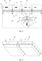
- Figure 3 comprises a circled area B that shows a detailed view of a portion of figure 3 .
- Corresponding features of the first and second embodiments are denoted with corresponding reference numbers, and the description of the features of the first embodiment may also apply to the second embodiment unless described otherwise.
- the suspended ceiling 204 comprises a grid of profiles 207.
- the grid of profiles 207 may comprise longitudinal and latitudinal profiles 207.
- the profiles 207 may be suspended from the ceiling 105 by suspending elements 108.
- the suspending elements 108 may be wires, bars or profiles that support the profiles 207 in a vertical direction, and the height of the suspending elements 108 may be adjusted depending on the height of the plenum space 103.
- the profiles 207 support a plurality of ceiling tiles 209. In figure 3 , four ceiling tiles 209 are shown.
- a profile 207 may comprise at least one flange 210 for supporting the ceiling tiles 209.
- a flange 210 may protrude on each side of a profile 207, and a profile 207 may preferably comprise two flanges 210, one flange 210 arranged on each side in a horizontal, longitudinal direction of the profile 207.
- the ceiling tiles 209 may comprise a rebated edge or stepped notch 213.
- a stepped notch 213 may be provided along at least one edge of a ceiling tile 209. Stepped notches 213 may be provided on the edges of a ceiling tile 209 that are configured to rest on a profile 207.
- a ceiling tile 209 may comprise a stepped notch 213 on two opposite edges only, or alternatively, a ceiling tile 209 may comprise a stepped notch 213 on all four edges.
- the ceiling tiles 209 may further comprise spacer elements 220.
- the spacer elements 220 may be provided along a periphery of the ceiling tiles 209, and the spacer elements 220 may preferably be provided on the horizontal portion of a stepped notch 213.
- the spacer elements 220 are configured for separating a horizontal face of the ceiling tile 209 from the flange 210 of the profile 207, and may more specifically be configured for separating a horizontal face of a stepped notch 213 from the flange 210 of the profile 209.
- the air gaps 212 comprise openings formed by ceiling tiles 209 spaced apart from the profiles 207 by the spacer elements 220.
- the spacer elements 220 may be integrated elements of the ceiling tiles 209, and may as such be formed from the same material as the ceiling tiles 209.
- the spacer elements 220 may be machined elements of the ceiling tile 209, or may be separate elements glued or otherwise fixed to the ceiling tiles 209.
- the spacer elements 220 may alternatively be open structures or made from an air-permeable material, such that air may flow through the spacer elements 220.
- the air gaps 212 of the second embodiment are also configured to have an increased air flow area as a function of increased distance from the air inlet 102.
- the height of the spacer elements 220 may increase.
- the height of the spacer elements 220 provided on one ceiling tile 209 may be approximately the same, but the height may increase from one ceiling element 209 to the next.
- the left ceiling tile 209 is arranged closer to the air inlet 102 than the right ceiling tile 209. This is illustrated in the circled area B of figure 1 , where a height D1 of the spacer elements 220 of the left ceiling tile 209 is less than the height D2 of the spacer elements 220 of the right ceiling tile 209.
- the right ceiling tile 209 being further away from the air inlet 102 than the left ceiling tile 209. This height difference is also visible in figure 4 .
- the height of the spacer elements 220 may increase for every two, three, etc. ceiling tile 209, as a function of increased distance from the air inlet 102. As the height of the spacer elements 220 increase, the height of the stepped notch 213 the spacer elements 220 are provided on may correspondingly increase. As such, the lower surfaces 214 of the ceiling tiles 109 may be arranged planar, even though the height of the spacer elements 220 increase.
- a ceiling tile 209 is preferably shaped right-angled. As such, a ceiling tile 209 may preferably be square or rectangular. A ceiling tile 209 may rest on at least two profiles 207, and two rows of profiles 207 may as such support one row of ceiling tiles 209 arranged between them. Alternatively, a ceiling tile 209 may rest on four profiles 207, where one profile 207 supports one of the four sides of the ceiling tile 209. Any number of spacer elements 220 may be provided on one ceiling tile 209, but preferably at least one spacer element 220 may be provided on each corner of a ceiling tile 209.
- the flow of air from the diffuse ceiling ventilation system 201 is controlled and evenly distributed into the one or more rooms 6 below.
- the air flow from the plenum space 103 to the room 106 is evenly distributed across the diffuse ceiling ventilation system 201, as indicated in figure 3 by vertical arrows.
- the air flows through the air gaps 212 formed between ceiling tiles 209 spaced apart from the profiles 108 by the spacer elements 220.
- the ridge and air gaps of the first embodiment may beneficially be combined with the spacer elements of the second embodiment, and the ceiling tiles may or may not comprise a stepped notch along the periphery.
- a diffuse ceiling ventilation system 301 according to a third embodiment is described.
- Corresponding features of the first and third embodiments are denoted with corresponding reference numbers, and the description of the features of the first embodiment may also apply to the third embodiment unless described otherwise.
- a suspended ceiling 304 of the diffuse ceiling ventilation system 301 comprises a grid of profiles 307.
- the profiles 307 are displaced parallel to each other, and each ceiling tile 309 may rest on two profiles 307 arranged on two opposite sides of the ceiling tile 309.
- the profiles 307 may or may not comprise flanges for supporting the ceiling tiles 309.
- the suspended ceiling 304 may as such not comprise any lateral profiles, and the ceiling tiles 309 may be arranged adjacent each other in a longitudinal direction. Two adjacent ceiling tiles 309 may abut each other, or be displaced in the vicinity of each other.
- Air gaps 312 are thus formed between two adjacent ceiling tiles 309.
- the air gaps 312 may be formed from cut-outs in the ceiling tiles 309, allowing the ceiling tiles 309 to abut each other.
- the air gaps 312 may be formed due to a distance between two adjacent ceiling tiles 309. As the distance from the air inlet 102 increases, the distance between two adjacent ceiling tiles 309 may increase, or the cut-outs may increase in size. In figure 5 , the air gap 312 formed between the ceiling tile 309 to the left and the ceiling tile 309 in the middle has a smaller air flow area than the air gap 312 formed between the ceiling tile 309 in the middle and the ceiling tile 309 to the right.
- the air gaps 312 are thus configured to increase in size or number, and thus have an increased air flow area as a function of increased distance from the air inlet 102.
- a diffuse ceiling ventilation system 301 comprising air gaps 312 formed between adjacent ceiling tiles 309 may advantageously comprise profiles and ceiling tiles according to the first and/or second embodiment.
- ceiling tiles 409 for a diffuse ceiling ventilation system 401 are described.
- Corresponding features of the first, second and fourth embodiments are denoted with corresponding reference numbers, and the description of the features of the first and second embodiment may also apply to the fourth embodiment unless described otherwise.
- the ceiling tiles 409 comprise spacer elements 420.
- the spacer elements 420 may be provided along a periphery of the ceiling tiles 409, and the spacer elements 420 may preferably be provided on the horizontal portion of a rebated edge or stepped notch 413.
- the spacer elements 420 may be formed elongate, and may extend in a direction along the edge of a ceiling tile 409.
- the spacer elements 420 are configured for separating a horizontal face of the ceiling tile 409 from a flange of a profile (not shown in figure 6 ) as described with reference to the first and second embodiments.
- the spacer elements 420 may more specifically be configured for separating a horizontal face of a stepped notch 413 from the flange of the profile.
- the spacer elements 420 are solid, such that air may not flow through the spacer elements 420, but must flow around them.
- the solid spacer elements 420 may be integrated elements of the ceiling tiles 409, and may as such be formed from the same material as the ceiling tiles 409.
- the solid spacer elements 420 may be machined elements of the ceiling tile 409, or may be separate elements glued or otherwise fixed to the ceiling tiles 409.
- the air gaps 412 comprise openings formed between each adjacent spacer element 420 and between the ceiling tiles 409 spaced apart from the profiles by the spacer elements 420.
- the air gaps 412 of the fourth embodiment are configured to have an increased air flow area as a function of increased distance from an air inlet.
- the height of the spacer elements 420 provided on the ceiling tiles 409 may be the same, but the distance between the spacer elements 420 may increase from one ceiling element 409 to the next.
- the left ceiling tile 409 is arranged closer to the air inlet than the right ceiling tile 409. A distance D1 between adjacent spacer elements 420 of the left ceiling tile 409 is less than the distance D2 between adjacent spacer elements 420 of the right ceiling tile 409.
- the distance between the spacer elements 420 may increase for every two, three, etc. ceiling tile 409, as a function of increased distance from the air inlet.
- the height of the spacer elements 420 may be constant for all ceiling tiles 409, the height of the stepped notch 413 of the ceiling tiles 409 may also be constant.
- the lower surfaces 414 of the ceiling tiles 409 may thereby be arranged planar.
- the features of the ceiling tiles and/or profiles described with reference to the first, second, third and fourth embodiments may beneficially be combined.
Landscapes
- Engineering & Computer Science (AREA)
- Architecture (AREA)
- Physics & Mathematics (AREA)
- Chemical & Material Sciences (AREA)
- Combustion & Propulsion (AREA)
- Mechanical Engineering (AREA)
- General Engineering & Computer Science (AREA)
- Electromagnetism (AREA)
- Civil Engineering (AREA)
- Structural Engineering (AREA)
- Fluid Mechanics (AREA)
- Building Environments (AREA)
Priority Applications (2)
| Application Number | Priority Date | Filing Date | Title |
|---|---|---|---|
| EP22161852.3A EP4246049A1 (de) | 2022-03-14 | 2022-03-14 | Diffusions-deckenlüftungssystem |
| PCT/EP2023/055986 WO2023174787A1 (en) | 2022-03-14 | 2023-03-09 | A diffuse ceiling ventilation system |
Applications Claiming Priority (1)
| Application Number | Priority Date | Filing Date | Title |
|---|---|---|---|
| EP22161852.3A EP4246049A1 (de) | 2022-03-14 | 2022-03-14 | Diffusions-deckenlüftungssystem |
Publications (1)
| Publication Number | Publication Date |
|---|---|
| EP4246049A1 true EP4246049A1 (de) | 2023-09-20 |
Family
ID=80738658
Family Applications (1)
| Application Number | Title | Priority Date | Filing Date |
|---|---|---|---|
| EP22161852.3A Pending EP4246049A1 (de) | 2022-03-14 | 2022-03-14 | Diffusions-deckenlüftungssystem |
Country Status (2)
| Country | Link |
|---|---|
| EP (1) | EP4246049A1 (de) |
| WO (1) | WO2023174787A1 (de) |
Citations (6)
| Publication number | Priority date | Publication date | Assignee | Title |
|---|---|---|---|---|
| US3088392A (en) * | 1960-09-08 | 1963-05-07 | Owens Corning Fiberglass Corp | Duct construction |
| EP2365152A1 (de) * | 2010-03-05 | 2011-09-14 | Nederlandse Organisatie voor toegepast -natuurwetenschappelijk onderzoek TNO | Deckensystem mit Rahmenwerk und Platten und mit Mitteln zur Erzeugung von Belüftungslücken |
| EP2378023A1 (de) * | 2010-04-14 | 2011-10-19 | Nederlandse Organisatie voor toegepast -natuurwetenschappelijk onderzoek TNO | Deckensystem mit Rahmenwerk und Platten und mit Mitteln zur Erzeugung von Belüftungslücken |
| US20190323233A1 (en) * | 2018-03-31 | 2019-10-24 | Certainteed Ceilings Corporation | Vented suspension ceiling beam and suspension ceiling system |
| EP3879044A1 (de) * | 2020-03-13 | 2021-09-15 | Saint-Gobain Ecophon AB | Deckenplatte und abgehängtes deckensystem mit solch einer deckenplatte |
| NL2025707B1 (en) * | 2020-05-29 | 2022-01-13 | Goflow Tech Ip B V | Ventilation system |
-
2022
- 2022-03-14 EP EP22161852.3A patent/EP4246049A1/de active Pending
-
2023
- 2023-03-09 WO PCT/EP2023/055986 patent/WO2023174787A1/en not_active Ceased
Patent Citations (6)
| Publication number | Priority date | Publication date | Assignee | Title |
|---|---|---|---|---|
| US3088392A (en) * | 1960-09-08 | 1963-05-07 | Owens Corning Fiberglass Corp | Duct construction |
| EP2365152A1 (de) * | 2010-03-05 | 2011-09-14 | Nederlandse Organisatie voor toegepast -natuurwetenschappelijk onderzoek TNO | Deckensystem mit Rahmenwerk und Platten und mit Mitteln zur Erzeugung von Belüftungslücken |
| EP2378023A1 (de) * | 2010-04-14 | 2011-10-19 | Nederlandse Organisatie voor toegepast -natuurwetenschappelijk onderzoek TNO | Deckensystem mit Rahmenwerk und Platten und mit Mitteln zur Erzeugung von Belüftungslücken |
| US20190323233A1 (en) * | 2018-03-31 | 2019-10-24 | Certainteed Ceilings Corporation | Vented suspension ceiling beam and suspension ceiling system |
| EP3879044A1 (de) * | 2020-03-13 | 2021-09-15 | Saint-Gobain Ecophon AB | Deckenplatte und abgehängtes deckensystem mit solch einer deckenplatte |
| NL2025707B1 (en) * | 2020-05-29 | 2022-01-13 | Goflow Tech Ip B V | Ventilation system |
Also Published As
| Publication number | Publication date |
|---|---|
| WO2023174787A1 (en) | 2023-09-21 |
Similar Documents
| Publication | Publication Date | Title |
|---|---|---|
| US11933045B2 (en) | Ceiling system | |
| US7546715B2 (en) | Structurally integrated accessible floor system | |
| US3202077A (en) | Expansion channel | |
| US20090282766A1 (en) | Structurally integrated accessible floor system | |
| US20110277405A1 (en) | Modular building panel and duct system | |
| US3353472A (en) | Dropped ceiling ventilator apparatus | |
| EP4246049A1 (de) | Diffusions-deckenlüftungssystem | |
| EP1407089B1 (de) | Konstruktiv integriertes, zugängliches bodensystem | |
| US10927555B2 (en) | Method for improving the ventilation effectiveness of large conditioned air plenum environments including such environments in multilevel raised floor electro-mechanical distribution systems | |
| US11952777B2 (en) | Modular ceiling accessible one by one, hidden grid, resting on all four sides, allowing for reduced thickness and larger formats | |
| US20170273225A1 (en) | Air-grate floor panel sub-plenum retrofit add on multi-directional plume | |
| CN210713965U (zh) | 一种洁净室 | |
| EP2365152A1 (de) | Deckensystem mit Rahmenwerk und Platten und mit Mitteln zur Erzeugung von Belüftungslücken | |
| JP7053389B2 (ja) | 騒音低減方法及び天井裏構造 | |
| US20210189722A1 (en) | Pre-cast concrete flooring systems and methods of use | |
| JP6576881B2 (ja) | 建物の空調設備 | |
| EP2378023A1 (de) | Deckensystem mit Rahmenwerk und Platten und mit Mitteln zur Erzeugung von Belüftungslücken | |
| JPH11230608A (ja) | ユニット式建物の通風ダクトの接続構造 | |
| CN108603372B (zh) | 悬挂式墙壁轨道系统 | |
| US20240368883A1 (en) | Ceiling system | |
| US3444800A (en) | Ventilating partition construction | |
| EP1579079B1 (de) | Verfahren und vorrichtung zur lüftung von fundamenten | |
| JP2003502536A (ja) | 換気システムのスクリーン装置 | |
| JPS6266039A (ja) | 清浄作業室設備 | |
| KR20260041472A (ko) | 클린룸용 천장패널 |
Legal Events
| Date | Code | Title | Description |
|---|---|---|---|
| PUAI | Public reference made under article 153(3) epc to a published international application that has entered the european phase |
Free format text: ORIGINAL CODE: 0009012 |
|
| STAA | Information on the status of an ep patent application or granted ep patent |
Free format text: STATUS: THE APPLICATION HAS BEEN PUBLISHED |
|
| AK | Designated contracting states |
Kind code of ref document: A1 Designated state(s): AL AT BE BG CH CY CZ DE DK EE ES FI FR GB GR HR HU IE IS IT LI LT LU LV MC MK MT NL NO PL PT RO RS SE SI SK SM TR |
|
| STAA | Information on the status of an ep patent application or granted ep patent |
Free format text: STATUS: REQUEST FOR EXAMINATION WAS MADE |
|
| 17P | Request for examination filed |
Effective date: 20240313 |
|
| RBV | Designated contracting states (corrected) |
Designated state(s): AL AT BE BG CH CY CZ DE DK EE ES FI FR GB GR HR HU IE IS IT LI LT LU LV MC MK MT NL NO PL PT RO RS SE SI SK SM TR |
|
| GRAP | Despatch of communication of intention to grant a patent |
Free format text: ORIGINAL CODE: EPIDOSNIGR1 |
|
| STAA | Information on the status of an ep patent application or granted ep patent |
Free format text: STATUS: GRANT OF PATENT IS INTENDED |
|
| INTG | Intention to grant announced |
Effective date: 20251218 |
|
| GRAS | Grant fee paid |
Free format text: ORIGINAL CODE: EPIDOSNIGR3 |
|
| GRAA | (expected) grant |
Free format text: ORIGINAL CODE: 0009210 |
|
| STAA | Information on the status of an ep patent application or granted ep patent |
Free format text: STATUS: THE PATENT HAS BEEN GRANTED |