EP4246080A1 - Accumulateur stratifié pour liquide caloporteur pour une installation de chauffage et/ou de refroidissement - Google Patents
Accumulateur stratifié pour liquide caloporteur pour une installation de chauffage et/ou de refroidissement Download PDFInfo
- Publication number
- EP4246080A1 EP4246080A1 EP23154226.7A EP23154226A EP4246080A1 EP 4246080 A1 EP4246080 A1 EP 4246080A1 EP 23154226 A EP23154226 A EP 23154226A EP 4246080 A1 EP4246080 A1 EP 4246080A1
- Authority
- EP
- European Patent Office
- Prior art keywords
- opening
- barrier element
- layered storage
- chamber
- connection
- Prior art date
- Legal status (The legal status is an assumption and is not a legal conclusion. Google has not performed a legal analysis and makes no representation as to the accuracy of the status listed.)
- Granted
Links
Images

Classifications
-
- F—MECHANICAL ENGINEERING; LIGHTING; HEATING; WEAPONS; BLASTING
- F28—HEAT EXCHANGE IN GENERAL
- F28D—HEAT-EXCHANGE APPARATUS, NOT PROVIDED FOR IN ANOTHER SUBCLASS, IN WHICH THE HEAT-EXCHANGE MEDIA DO NOT COME INTO DIRECT CONTACT
- F28D20/00—Heat storage plants or apparatus in general; Regenerative heat-exchange apparatus not covered by groups F28D17/00 or F28D19/00
- F28D20/0034—Heat storage plants or apparatus in general; Regenerative heat-exchange apparatus not covered by groups F28D17/00 or F28D19/00 using liquid heat storage material
- F28D20/0039—Heat storage plants or apparatus in general; Regenerative heat-exchange apparatus not covered by groups F28D17/00 or F28D19/00 using liquid heat storage material with stratification of the heat storage material
-
- F—MECHANICAL ENGINEERING; LIGHTING; HEATING; WEAPONS; BLASTING
- F28—HEAT EXCHANGE IN GENERAL
- F28D—HEAT-EXCHANGE APPARATUS, NOT PROVIDED FOR IN ANOTHER SUBCLASS, IN WHICH THE HEAT-EXCHANGE MEDIA DO NOT COME INTO DIRECT CONTACT
- F28D20/00—Heat storage plants or apparatus in general; Regenerative heat-exchange apparatus not covered by groups F28D17/00 or F28D19/00
- F28D2020/0065—Details, e.g. particular heat storage tanks, auxiliary members within tanks
- F28D2020/0069—Distributing arrangements; Fluid deflecting means
-
- F—MECHANICAL ENGINEERING; LIGHTING; HEATING; WEAPONS; BLASTING
- F28—HEAT EXCHANGE IN GENERAL
- F28D—HEAT-EXCHANGE APPARATUS, NOT PROVIDED FOR IN ANOTHER SUBCLASS, IN WHICH THE HEAT-EXCHANGE MEDIA DO NOT COME INTO DIRECT CONTACT
- F28D20/00—Heat storage plants or apparatus in general; Regenerative heat-exchange apparatus not covered by groups F28D17/00 or F28D19/00
- F28D2020/0065—Details, e.g. particular heat storage tanks, auxiliary members within tanks
- F28D2020/0086—Partitions
-
- Y—GENERAL TAGGING OF NEW TECHNOLOGICAL DEVELOPMENTS; GENERAL TAGGING OF CROSS-SECTIONAL TECHNOLOGIES SPANNING OVER SEVERAL SECTIONS OF THE IPC; TECHNICAL SUBJECTS COVERED BY FORMER USPC CROSS-REFERENCE ART COLLECTIONS [XRACs] AND DIGESTS
- Y02—TECHNOLOGIES OR APPLICATIONS FOR MITIGATION OR ADAPTATION AGAINST CLIMATE CHANGE
- Y02E—REDUCTION OF GREENHOUSE GAS [GHG] EMISSIONS, RELATED TO ENERGY GENERATION, TRANSMISSION OR DISTRIBUTION
- Y02E60/00—Enabling technologies; Technologies with a potential or indirect contribution to GHG emissions mitigation
- Y02E60/14—Thermal energy storage
Definitions
- the present invention relates to a layered storage tank for a heat transfer fluid for a heating and/or cooling system with the features of the preamble of claim 1.
- Such a layered storage is, for example, in the EP 2481991 A2 disclosed.
- the best possible mixing and thus the most homogeneous temperature should prevail in the at least one connection chamber.
- mixing is not desired in the at least one buffer chamber. Rather, the heat transfer fluid should be stored higher in the at least one buffer chamber when it is warmer, and accordingly lie lower in the at least one buffer chamber when it is colder.
- the temperature in the at least one buffer chamber in each layer should be constant and should be higher, the higher the layer is.
- the EP 2481991 A2 In order to decouple the turbulence in the at least one connection chamber from the at least one buffer chamber, the EP 2481991 A2 a connection via a gap, which achieves very good results in practice. However, the stratified temperature distribution in the at least one buffer chamber is not yet ideal.
- the object of the invention is to provide a layered storage tank which offers an improved layered temperature distribution and/or a lower hydraulic resistance through the barrier elements.
- the DE 102007009199 A1 is another example from the prior art, although dedicated temperature zones are disclosed.
- the at least one centrally arranged second opening is in itself counter-intuitive because turbulences from the at least one connection chamber can thereby more easily reach the at least one buffer chamber.
- investigations by the applicant have surprisingly shown that the at least one first barrier element with the peripheral first opening alone is able to hold back these turbulences, so that a laminar flow results through the at least one second opening.
- the at least one second opening is arranged centrally with respect to the at least one buffer chamber, the stratified temperature distribution in the at least one buffer chamber is disturbed as little as possible because no spatial imbalance in the temperature distribution is caused when heat transfer fluid flows through the at least one second opening flows.
- a further advantage of the invention is that the hydraulic resistance for overflow between the at least one connection chamber and the at least one buffer chamber does not have to be increased compared to the prior art.
- connections can be present exclusively in the at least one connection chamber, so that the at least one buffer chamber is free of connections. In principle, however, it is also conceivable to provide connections in the at least one buffer chamber.
- first opening is arranged peripherally can be understood as meaning that it is arranged essentially on the edge of the at least one first connection chamber, because less turbulence tends to occur here.
- the at least one second barrier element is arranged between the at least one first barrier element and the at least one buffer chamber.
- the heat transfer fluid can pass from the at least one connection chamber via the first opening into a space between the at least one first barrier element and the at least one second barrier element and from there can reach the at least one buffer chamber via the at least one second opening ( or vice versa from the at least one buffer chamber into the at least one connection chamber).
- the at least one connection chamber is in fluid communication with the at least one buffer chamber.
- connection chamber and/or the at least one buffer chamber can preferably be designed substantially symmetrically with respect to a vertical axis.
- a first barrier element and a second barrier element can be arranged between the connection chambers and the buffer chamber, wherein the second barrier element can be arranged between the first barrier element and the buffer chamber.
- buffer chambers are provided in an analogous manner, for example two buffer chambers arranged one above the other, which are preferably separated from one another by a connection chamber and two corresponding pairs of barrier elements. Connection chambers can then be connected to the buffer chambers, etc.
- all connections for heat transfer fluid with a colder temperature can be on the second connection chamber and all connections for heat transfer fluid with a warmer temperature can be on the first connection chamber.
- the at least one connection chamber and the at least one buffer chamber can be arranged in the same container and separated from one another by the at least one first barrier element and the at least one second barrier element.
- connection chamber and/or the at least one buffer chamber and/or the common container can be insulated to minimize heat losses.
- the at least one first barrier element and/or the at least one second barrier element can be a sheet metal.
- the first opening and/or the at least one second opening can be created as a sheet metal cut.
- Water can preferably be used as the heat transfer fluid, although additives may optionally be present.
- Protection is also desired for a heating and/or cooling system with a layered storage tank according to the invention.
- the first opening extends to a wall of the layered storage, in particular of the at least one connection chamber.
- the first opening can also be at a certain distance (preferably not more than twice the thickness of the first opening, particularly preferably not more than one thickness of the first opening) from the wall of the at least one connection chamber.
- the first opening can be arranged such that in a top view of the at least one first barrier element and the at least one second barrier element there is a distance between the first opening and the at least one second opening, that is, in particular, no overlap between the first opening and which has at least one second opening.
- the first opening can be designed in the form of a circular ring segment.
- the first opening in particular the circular ring segment, can span an angle between 60° and 110°, preferably between 70° and 100° and particularly preferably between 80° and 90°. This means that the first opening can preferably not be present completely around the periphery, but can only extend over the specified angular range.
- a thickness of the first opening can essentially correspond to a distance between the at least one first barrier element and the at least one second barrier element.
- the thickness of the first opening can be between 5% and 30%, preferably between 10% and 25% and particularly preferably between 15% and 20%, of a radius of the at least one connection chamber.
- a plurality of second openings can be provided, which can be arranged in the center of the at least one second barrier element.
- the second openings can be in the form of a perforated plate.
- the second openings can preferably each be circular or have other shapes.
- the at least one second barrier element may have a peripheral impermeable part and a central, at least partially permeable part in which the at least one second opening is arranged.
- a ratio of an area between the permeable part and the impermeable part can be between 60% and 90%, preferably between 70% and 85% and particularly preferably between 75% and 85%.
- the ratio can preferably be 80%.
- a ratio of an area of the at least one second opening to an area of the at least partially permeable region can be between 10% and 80%, preferably between 20% and 60% and particularly preferably between 30% and 40%.
- the stratified storage tank and/or the at least one connection chamber and/or the at least one buffer chamber can have a substantially cylindrical basic shape.
- a circular cylindrical basic shape can be preferred, although general cylindrical basic shapes are certainly conceivable.
- the essentially cylindrical basic shape can of course be modified, for example with rounded edges and/or with connections.
- the at least one first barrier element and/or the at least one second barrier element can have a substantially circular basic shape.
- the first opening and the at least one second opening are present in the at least one first barrier element or in the at least one second barrier element.
- a swirling element preferably in the form of a cylindrical perforated plate, can be arranged essentially centrally in the at least one connection chamber.
- connection - preferably all connections - can have a tubular element which projects into an interior of the at least one connection chamber.
- a length of the tubular element may be greater than a thickness of the first opening.
- the tubular element can protrude beyond the first opening, so that volume flows at the connections cause as little turbulence as possible at the edge of the at least one connection chamber, in particular at the location of the first opening.
- Fig. 1a shows a layered storage device 1 according to the invention in a side view.
- Connections 12 which open into connection chambers 2 mentioned below, can be seen from the outside.
- connection chambers 2 described below and the buffer chamber 3 are arranged in a common container in which the barrier elements 4, 6 are also arranged.
- the barrier elements 4, 6 divide the common container into a first connection chamber 2, which is located in the upper part of the container, into a buffer chamber 3 in the middle part of the container and a second connection chamber 2 in the lower part of the container.
- first barrier element 4 and a second barrier element 5 are provided between the first connection chamber 2 and the buffer chamber 3.
- the first barrier element 4 has a first opening 5, which in this exemplary embodiment reaches up to the container wall.
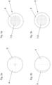
- the Fig. 2a to refer which shows this barrier element 4 in a view from above.
- the second barrier element 6 has a plurality of second openings 7, which lie centrally in a partially permeable area 9.
- the partially permeable area is simply designed as a perforated sheet metal.
- a first barrier element 4 and a second barrier element 6 are also arranged in mirrored form between the buffer chamber 3 and the second connection chamber 2 in the lower part of the container.
- the stratified storage tank 1 therefore functions practically completely symmetrically with respect to the upper, first connection chamber 2 for hot water and the lower, second connection chamber 2 for cold water.
- a swirling element 11 is also present in each connection chamber 2.
- the swirling element 11 first ensures that mixing with the remaining liquid in the connection chamber 2 takes place. As a result, there is a relatively homogeneous temperature in the upper, first connection chamber 2.
- the volume flow will next pass from the space between the first barrier element 4 and the second barrier element 6 through the second openings into the buffer chamber 3.
- the volume flow will enter the buffer chamber 3 with approximately the same symmetry that the buffer chamber 3 already has.
- the stratified temperature distribution in the buffer chamber 3 is disturbed as little as possible.
- the first opening and the second openings together allow the volume flow passing through to be quite high compared to the prior art without the layer structure in the buffer chamber 3 collapsing.
- the functionality described here in this exemplary embodiment is analogous to volume flows that are taken from the upper, first connection chamber 2, or that are introduced or taken into or from the lower second connection chamber 2 for colder water.
- the amount of heat transfer fluid in the layered storage tank 1 remains constant, i.e. the incoming and outgoing volume flows are essentially balanced.
- Fig. 1c shows the exemplary embodiment from the Figures 1a and 1b in a view from above, with pipe elements 13 indicated by dashed lines (see also Fig. 1b ), which extend the connections 12 into the connection chamber 2.
- the incoming and outgoing volume flows do not flow past the edge of the layered storage tank 1, so that turbulence is kept as far away as possible from the first opening 5.
- first opening 5 in the upper first barrier element 4 was arranged on the other side compared to that in the lower first barrier element 4.
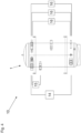
- Fig. 4 shows an exemplary embodiment of a heating and/or cooling system 10 with a stratified storage tank 1 according to the invention.
- a heat pump 14 can be provided, which removes colder heat transfer fluid from a lower connection chamber 2 and delivers warmer heat transfer fluid into an upper connection chamber 2.
- a condensing boiler 15 may be present, which removes heat transfer fluid, for example, from a buffer chamber 3 and delivers warmer heat transfer fluid into an upper connection chamber 2.
- heaters in particular underfloor heating 16, can be provided.
- more than one heat pump 14 and/or more than one condensing boiler 15 may be provided.
- other consumers can be provided as underfloor heating systems 16, which can of course also vary in number (i.e. of course it doesn't have to be exactly three).
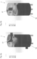
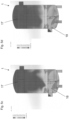
- the Figures 5a to 5d show the simulation result at different times, namely after 30 seconds ( Fig. 5a ), after 60 seconds ( Fig. 5b ), after 120 seconds ( Fig. 5c ) and after 180 seconds ( Fig. 5d ).
- Fig. 5b The view of Fig. 5b was also rotated by 90° to show that there are no significantly different conditions even in a plane perpendicular to the plane of the drawing.
Landscapes
- Engineering & Computer Science (AREA)
- Physics & Mathematics (AREA)
- Thermal Sciences (AREA)
- Mechanical Engineering (AREA)
- General Engineering & Computer Science (AREA)
- Earth Drilling (AREA)
- Central Heating Systems (AREA)
Applications Claiming Priority (1)
| Application Number | Priority Date | Filing Date | Title |
|---|---|---|---|
| ATA67/2022A AT525348B1 (de) | 2022-03-15 | 2022-03-15 | Schichtspeicher für eine Wärmeträgerflüssigkeit für eine Heiz- und/oder Kühlanlage |
Publications (3)
| Publication Number | Publication Date |
|---|---|
| EP4246080A1 true EP4246080A1 (fr) | 2023-09-20 |
| EP4246080C0 EP4246080C0 (fr) | 2025-03-19 |
| EP4246080B1 EP4246080B1 (fr) | 2025-03-19 |
Family
ID=85150512
Family Applications (1)
| Application Number | Title | Priority Date | Filing Date |
|---|---|---|---|
| EP23154226.7A Active EP4246080B1 (fr) | 2022-03-15 | 2023-01-31 | Accumulateur stratifié pour liquide caloporteur pour une installation de chauffage et/ou de refroidissement |
Country Status (4)
| Country | Link |
|---|---|
| US (1) | US20230296327A1 (fr) |
| EP (1) | EP4246080B1 (fr) |
| AT (1) | AT525348B1 (fr) |
| PL (1) | PL4246080T3 (fr) |
Citations (8)
| Publication number | Priority date | Publication date | Assignee | Title |
|---|---|---|---|---|
| EP0154791A1 (fr) * | 1984-02-09 | 1985-09-18 | GebràDer Sulzer Aktiengesellschaft | Accumulateur de chaleur rempli d'eau pour installation de chauffage |
| US20030006239A1 (en) * | 2001-07-04 | 2003-01-09 | Sadahisa Onimaru | Heat storage tank |
| JP2004173897A (ja) * | 2002-11-27 | 2004-06-24 | Tiger Vacuum Bottle Co Ltd | 真空二重容器 |
| JP2004224153A (ja) * | 2003-01-22 | 2004-08-12 | Tiger Vacuum Bottle Co Ltd | 保温貯液容器 |
| DE102007009199A1 (de) | 2007-02-26 | 2008-09-04 | Kioto Clear Energy Ag | Wasserspeicher |
| EP2163745A1 (fr) * | 2008-09-16 | 2010-03-17 | Calsonic Kansei Corporation | Accumulateur de chaleur et son procédé de fabrication |
| EP2481991A2 (fr) | 2011-02-01 | 2012-08-01 | Rembert Zortea | Collecteur et distributeur pour une installation de chauffage ou de refroidissement |
| EP2765364A1 (fr) * | 2012-12-07 | 2014-08-13 | Vaillant GmbH | Mémoire en couches |
Family Cites Families (5)
| Publication number | Priority date | Publication date | Assignee | Title |
|---|---|---|---|---|
| US4598694A (en) * | 1985-01-08 | 1986-07-08 | Cromer Charles J | Water heater partition and method |
| US7584628B2 (en) * | 2006-06-29 | 2009-09-08 | Northrop Grumman Corporation | System for delivering coolant to a laser system |
| AT510578B1 (de) * | 2010-11-22 | 2012-05-15 | Vaillant Group Austria Gmbh | Schichtenspeicher |
| EP2738508B1 (fr) * | 2012-11-28 | 2015-08-12 | Solarenet S.r.l. | Réservoir modulaire |
| CN108645259B (zh) * | 2018-04-27 | 2020-04-24 | 湖北三江航天红林探控有限公司 | 一种高效率高温燃气快速降温装置 |
-
2022
- 2022-03-15 AT ATA67/2022A patent/AT525348B1/de active
-
2023
- 2023-01-31 EP EP23154226.7A patent/EP4246080B1/fr active Active
- 2023-01-31 PL PL23154226.7T patent/PL4246080T3/pl unknown
- 2023-03-09 US US18/119,514 patent/US20230296327A1/en active Pending
Patent Citations (8)
| Publication number | Priority date | Publication date | Assignee | Title |
|---|---|---|---|---|
| EP0154791A1 (fr) * | 1984-02-09 | 1985-09-18 | GebràDer Sulzer Aktiengesellschaft | Accumulateur de chaleur rempli d'eau pour installation de chauffage |
| US20030006239A1 (en) * | 2001-07-04 | 2003-01-09 | Sadahisa Onimaru | Heat storage tank |
| JP2004173897A (ja) * | 2002-11-27 | 2004-06-24 | Tiger Vacuum Bottle Co Ltd | 真空二重容器 |
| JP2004224153A (ja) * | 2003-01-22 | 2004-08-12 | Tiger Vacuum Bottle Co Ltd | 保温貯液容器 |
| DE102007009199A1 (de) | 2007-02-26 | 2008-09-04 | Kioto Clear Energy Ag | Wasserspeicher |
| EP2163745A1 (fr) * | 2008-09-16 | 2010-03-17 | Calsonic Kansei Corporation | Accumulateur de chaleur et son procédé de fabrication |
| EP2481991A2 (fr) | 2011-02-01 | 2012-08-01 | Rembert Zortea | Collecteur et distributeur pour une installation de chauffage ou de refroidissement |
| EP2765364A1 (fr) * | 2012-12-07 | 2014-08-13 | Vaillant GmbH | Mémoire en couches |
Also Published As
| Publication number | Publication date |
|---|---|
| EP4246080C0 (fr) | 2025-03-19 |
| EP4246080B1 (fr) | 2025-03-19 |
| US20230296327A1 (en) | 2023-09-21 |
| AT525348B1 (de) | 2023-03-15 |
| PL4246080T3 (pl) | 2025-06-16 |
| AT525348A4 (de) | 2023-03-15 |
Similar Documents
| Publication | Publication Date | Title |
|---|---|---|
| DE69422207T2 (de) | Plattenwärmetauscher und entsprechende Platten | |
| DE19819248C1 (de) | Flachrohr eines Heizungswärmetauschers oder Kühlers eines Kraftfahrzeugs | |
| EP2455696B1 (fr) | Accumulateur stratifié | |
| EP1400772A2 (fr) | Echangeur de chaleur à plaques | |
| EP1306638A2 (fr) | Echangeur de chaleur à plaques sans carter | |
| EP2213948A2 (fr) | Répartiteur de circuit de la cathode chaude | |
| DE112013004284T5 (de) | Wärmetauscher für Mikrokanal | |
| EP2476970A2 (fr) | Réservoir de fluide | |
| EP1878891B1 (fr) | Vase d'expansion séparé verticalement pour liquide de refroidissement | |
| DE19743563B4 (de) | Wärmeschichtspeicher | |
| DE102007009199A1 (de) | Wasserspeicher | |
| DE2722288A1 (de) | Plattenfoermiger verdampfer | |
| EP4246080B1 (fr) | Accumulateur stratifié pour liquide caloporteur pour une installation de chauffage et/ou de refroidissement | |
| DE102012100423B3 (de) | Schichtenspeicher | |
| DD270049A5 (de) | Temperierbarer tankcontainer | |
| DE1501235A1 (de) | Verfahren und Einrichtung zum Kuehlen einer Kammer | |
| DE202009003191U1 (de) | Kaskadeneinheit für eine Heizungsanlage mit zwei oder mehr Heizkesseln | |
| DE19722635C2 (de) | Innenbehälter für einen Heißwasserspeicher | |
| EP1760407A1 (fr) | Distributeur pour système de chauffage et de refroidissement | |
| DE202010006896U1 (de) | Sammler-Verteiler-Einheit mit hydraulischer Weiche | |
| DE102018006461B4 (de) | Wärmetauscher mit ineinanderragenden spitzwinkligen oder spitzdachartigen Platinen | |
| DE4222663C2 (de) | Heizregister, insbesondere für Trockeneinrichtungen | |
| DE112015005788T5 (de) | Wärmetauscher | |
| DE102011079635A1 (de) | Kühlplatte und Verfahren zu deren Herstellung sowie Verwendung der Kühlplatte | |
| EP2921787B1 (fr) | Module de régulation de température pour une paroi de bâtiment |
Legal Events
| Date | Code | Title | Description |
|---|---|---|---|
| PUAI | Public reference made under article 153(3) epc to a published international application that has entered the european phase |
Free format text: ORIGINAL CODE: 0009012 |
|
| STAA | Information on the status of an ep patent application or granted ep patent |
Free format text: STATUS: THE APPLICATION HAS BEEN PUBLISHED |
|
| AK | Designated contracting states |
Kind code of ref document: A1 Designated state(s): AL AT BE BG CH CY CZ DE DK EE ES FI FR GB GR HR HU IE IS IT LI LT LU LV MC ME MK MT NL NO PL PT RO RS SE SI SK SM TR |
|
| STAA | Information on the status of an ep patent application or granted ep patent |
Free format text: STATUS: REQUEST FOR EXAMINATION WAS MADE |
|
| 17P | Request for examination filed |
Effective date: 20240221 |
|
| RBV | Designated contracting states (corrected) |
Designated state(s): AL AT BE BG CH CY CZ DE DK EE ES FI FR GB GR HR HU IE IS IT LI LT LU LV MC ME MK MT NL NO PL PT RO RS SE SI SK SM TR |
|
| GRAP | Despatch of communication of intention to grant a patent |
Free format text: ORIGINAL CODE: EPIDOSNIGR1 |
|
| STAA | Information on the status of an ep patent application or granted ep patent |
Free format text: STATUS: GRANT OF PATENT IS INTENDED |
|
| INTG | Intention to grant announced |
Effective date: 20241204 |
|
| GRAS | Grant fee paid |
Free format text: ORIGINAL CODE: EPIDOSNIGR3 |
|
| GRAA | (expected) grant |
Free format text: ORIGINAL CODE: 0009210 |
|
| STAA | Information on the status of an ep patent application or granted ep patent |
Free format text: STATUS: THE PATENT HAS BEEN GRANTED |
|
| AK | Designated contracting states |
Kind code of ref document: B1 Designated state(s): AL AT BE BG CH CY CZ DE DK EE ES FI FR GB GR HR HU IE IS IT LI LT LU LV MC ME MK MT NL NO PL PT RO RS SE SI SK SM TR |
|
| REG | Reference to a national code |
Ref country code: GB Ref legal event code: FG4D Free format text: NOT ENGLISH |
|
| REG | Reference to a national code |
Ref country code: CH Ref legal event code: EP |
|
| REG | Reference to a national code |
Ref country code: DE Ref legal event code: R096 Ref document number: 502023000687 Country of ref document: DE |
|
| REG | Reference to a national code |
Ref country code: IE Ref legal event code: FG4D Free format text: LANGUAGE OF EP DOCUMENT: GERMAN |
|
| U01 | Request for unitary effect filed |
Effective date: 20250326 |
|
| U07 | Unitary effect registered |
Designated state(s): AT BE BG DE DK EE FI FR IT LT LU LV MT NL PT RO SE SI Effective date: 20250402 |
|
| REG | Reference to a national code |
Ref country code: SK Ref legal event code: T3 Ref document number: E 46209 Country of ref document: SK |
|
| PG25 | Lapsed in a contracting state [announced via postgrant information from national office to epo] |
Ref country code: RS Free format text: LAPSE BECAUSE OF FAILURE TO SUBMIT A TRANSLATION OF THE DESCRIPTION OR TO PAY THE FEE WITHIN THE PRESCRIBED TIME-LIMIT Effective date: 20250619 |
|
| PG25 | Lapsed in a contracting state [announced via postgrant information from national office to epo] |
Ref country code: NO Free format text: LAPSE BECAUSE OF FAILURE TO SUBMIT A TRANSLATION OF THE DESCRIPTION OR TO PAY THE FEE WITHIN THE PRESCRIBED TIME-LIMIT Effective date: 20250619 |
|
| PG25 | Lapsed in a contracting state [announced via postgrant information from national office to epo] |
Ref country code: HR Free format text: LAPSE BECAUSE OF FAILURE TO SUBMIT A TRANSLATION OF THE DESCRIPTION OR TO PAY THE FEE WITHIN THE PRESCRIBED TIME-LIMIT Effective date: 20250319 |
|
| PG25 | Lapsed in a contracting state [announced via postgrant information from national office to epo] |
Ref country code: GR Free format text: LAPSE BECAUSE OF FAILURE TO SUBMIT A TRANSLATION OF THE DESCRIPTION OR TO PAY THE FEE WITHIN THE PRESCRIBED TIME-LIMIT Effective date: 20250620 |
|
| PG25 | Lapsed in a contracting state [announced via postgrant information from national office to epo] |
Ref country code: SM Free format text: LAPSE BECAUSE OF FAILURE TO SUBMIT A TRANSLATION OF THE DESCRIPTION OR TO PAY THE FEE WITHIN THE PRESCRIBED TIME-LIMIT Effective date: 20250319 |
|
| PG25 | Lapsed in a contracting state [announced via postgrant information from national office to epo] |
Ref country code: ES Free format text: LAPSE BECAUSE OF FAILURE TO SUBMIT A TRANSLATION OF THE DESCRIPTION OR TO PAY THE FEE WITHIN THE PRESCRIBED TIME-LIMIT Effective date: 20250319 |
|
| PG25 | Lapsed in a contracting state [announced via postgrant information from national office to epo] |
Ref country code: CZ Free format text: LAPSE BECAUSE OF FAILURE TO SUBMIT A TRANSLATION OF THE DESCRIPTION OR TO PAY THE FEE WITHIN THE PRESCRIBED TIME-LIMIT Effective date: 20250319 |
|
| PG25 | Lapsed in a contracting state [announced via postgrant information from national office to epo] |
Ref country code: IS Free format text: LAPSE BECAUSE OF FAILURE TO SUBMIT A TRANSLATION OF THE DESCRIPTION OR TO PAY THE FEE WITHIN THE PRESCRIBED TIME-LIMIT Effective date: 20250719 |
|
| PLBE | No opposition filed within time limit |
Free format text: ORIGINAL CODE: 0009261 |
|
| STAA | Information on the status of an ep patent application or granted ep patent |
Free format text: STATUS: NO OPPOSITION FILED WITHIN TIME LIMIT |
|
| REG | Reference to a national code |
Ref country code: CH Ref legal event code: L10 Free format text: ST27 STATUS EVENT CODE: U-0-0-L10-L00 (AS PROVIDED BY THE NATIONAL OFFICE) Effective date: 20260128 |
|
| U20 | Renewal fee for the european patent with unitary effect paid |
Year of fee payment: 4 Effective date: 20251219 |
|
| REG | Reference to a national code |
Ref country code: CH Ref legal event code: U11 Free format text: ST27 STATUS EVENT CODE: U-0-0-U10-U11 (AS PROVIDED BY THE NATIONAL OFFICE) Effective date: 20260201 |
|
| 26N | No opposition filed |
Effective date: 20251222 |
|
| PGFP | Annual fee paid to national office [announced via postgrant information from national office to epo] |
Ref country code: CH Payment date: 20260201 Year of fee payment: 4 |
|
| PGFP | Annual fee paid to national office [announced via postgrant information from national office to epo] |
Ref country code: PL Payment date: 20260107 Year of fee payment: 4 |
|
| PGFP | Annual fee paid to national office [announced via postgrant information from national office to epo] |
Ref country code: SK Payment date: 20260113 Year of fee payment: 4 |