EP4246082B1 - Tête de coulasse d'un arme de chasse ou de sport - Google Patents
Tête de coulasse d'un arme de chasse ou de sport Download PDFInfo
- Publication number
- EP4246082B1 EP4246082B1 EP22162494.3A EP22162494A EP4246082B1 EP 4246082 B1 EP4246082 B1 EP 4246082B1 EP 22162494 A EP22162494 A EP 22162494A EP 4246082 B1 EP4246082 B1 EP 4246082B1
- Authority
- EP
- European Patent Office
- Prior art keywords
- bolt
- bolt head
- hunting
- locking
- head
- Prior art date
- Legal status (The legal status is an assumption and is not a legal conclusion. Google has not performed a legal analysis and makes no representation as to the accuracy of the status listed.)
- Active
Links
Images




Classifications
-
- F—MECHANICAL ENGINEERING; LIGHTING; HEATING; WEAPONS; BLASTING
- F41—WEAPONS
- F41A—FUNCTIONAL FEATURES OR DETAILS COMMON TO BOTH SMALLARMS AND ORDNANCE, e.g. CANNONS; MOUNTINGS FOR SMALLARMS OR ORDNANCE
- F41A3/00—Breech mechanisms, e.g. locks
- F41A3/12—Bolt action, i.e. the main breech opening movement being parallel to the barrel axis
-
- F—MECHANICAL ENGINEERING; LIGHTING; HEATING; WEAPONS; BLASTING
- F41—WEAPONS
- F41A—FUNCTIONAL FEATURES OR DETAILS COMMON TO BOTH SMALLARMS AND ORDNANCE, e.g. CANNONS; MOUNTINGS FOR SMALLARMS OR ORDNANCE
- F41A3/00—Breech mechanisms, e.g. locks
- F41A3/12—Bolt action, i.e. the main breech opening movement being parallel to the barrel axis
- F41A3/14—Rigid bolt locks, i.e. having locking elements rigidly mounted on the bolt or bolt handle and on the barrel or breech-housing respectively
-
- F—MECHANICAL ENGINEERING; LIGHTING; HEATING; WEAPONS; BLASTING
- F41—WEAPONS
- F41A—FUNCTIONAL FEATURES OR DETAILS COMMON TO BOTH SMALLARMS AND ORDNANCE, e.g. CANNONS; MOUNTINGS FOR SMALLARMS OR ORDNANCE
- F41A3/00—Breech mechanisms, e.g. locks
- F41A3/12—Bolt action, i.e. the main breech opening movement being parallel to the barrel axis
- F41A3/14—Rigid bolt locks, i.e. having locking elements rigidly mounted on the bolt or bolt handle and on the barrel or breech-housing respectively
- F41A3/16—Rigid bolt locks, i.e. having locking elements rigidly mounted on the bolt or bolt handle and on the barrel or breech-housing respectively the locking elements effecting a rotary movement about the barrel axis, e.g. rotating cylinder bolt locks
-
- F—MECHANICAL ENGINEERING; LIGHTING; HEATING; WEAPONS; BLASTING
- F41—WEAPONS
- F41A—FUNCTIONAL FEATURES OR DETAILS COMMON TO BOTH SMALLARMS AND ORDNANCE, e.g. CANNONS; MOUNTINGS FOR SMALLARMS OR ORDNANCE
- F41A3/00—Breech mechanisms, e.g. locks
- F41A3/12—Bolt action, i.e. the main breech opening movement being parallel to the barrel axis
- F41A3/14—Rigid bolt locks, i.e. having locking elements rigidly mounted on the bolt or bolt handle and on the barrel or breech-housing respectively
- F41A3/16—Rigid bolt locks, i.e. having locking elements rigidly mounted on the bolt or bolt handle and on the barrel or breech-housing respectively the locking elements effecting a rotary movement about the barrel axis, e.g. rotating cylinder bolt locks
- F41A3/18—Rigid bolt locks, i.e. having locking elements rigidly mounted on the bolt or bolt handle and on the barrel or breech-housing respectively the locking elements effecting a rotary movement about the barrel axis, e.g. rotating cylinder bolt locks hand-operated
-
- F—MECHANICAL ENGINEERING; LIGHTING; HEATING; WEAPONS; BLASTING
- F41—WEAPONS
- F41A—FUNCTIONAL FEATURES OR DETAILS COMMON TO BOTH SMALLARMS AND ORDNANCE, e.g. CANNONS; MOUNTINGS FOR SMALLARMS OR ORDNANCE
- F41A3/00—Breech mechanisms, e.g. locks
- F41A3/12—Bolt action, i.e. the main breech opening movement being parallel to the barrel axis
- F41A3/14—Rigid bolt locks, i.e. having locking elements rigidly mounted on the bolt or bolt handle and on the barrel or breech-housing respectively
- F41A3/16—Rigid bolt locks, i.e. having locking elements rigidly mounted on the bolt or bolt handle and on the barrel or breech-housing respectively the locking elements effecting a rotary movement about the barrel axis, e.g. rotating cylinder bolt locks
- F41A3/18—Rigid bolt locks, i.e. having locking elements rigidly mounted on the bolt or bolt handle and on the barrel or breech-housing respectively the locking elements effecting a rotary movement about the barrel axis, e.g. rotating cylinder bolt locks hand-operated
- F41A3/20—Straight-pull operated bolt locks, i.e. the operating hand effecting only a straight movement parallel to the barrel axis
Definitions
- the subject matter of the invention is a bolt head of a hunting or sporting weapon as part of a weapon bolt according to the preamble of patent claim 1.
- the bolt is a component of a breech-loading rifle and closes the barrel at the rear.
- the bolt prevents propellant gases from escaping to the rear. It must be stable enough to withstand the pressure of these gases.
- the bolt holds the cartridges in place in the barrel and seals them by sealing the case material. The bolt must therefore maintain the seal or support of the cartridge during firing and must not open before the gas pressure has dropped to a safe level.
- the bolt can perform other functions such as loading, firing, securing and unloading the weapon.
- the bolt head In the Blaser R8 weapon, the bolt head is changed in such a way that the entire bolt slide must be removed towards the rear of the buttstock by pulling it completely out of the weapon and removing it. It must then be turned 180° until its underside is accessible, and on the underside there is a bolt latch called the chamber lock.
- the bolt latch is operated with the finger when it is swung up, and then, after operating this chamber lock, the bolt head can be pulled out of the bolt slide that has been removed from the weapon.
- the problem of caliber change is also addressed by the DE 39 06 496 A1
- the publication proposes a barrel changing unit, a cylinder bolt changing unit and a magazine changing unit.
- the barrel is first removed with the bolt open.
- the bolt head is then removed from the guide bearing by removing a stud screw.
- this has the disadvantage that the barrel has to be completely removed to gain access to a stud screw holding the bolt head.
- the bolt head When the bolt slide is moved into an exposed ejection opening in the firing direction, the bolt head is freely accessible from the front, replaceable and is secured with a stud screw. However, this must first be loosened using a tool in order to remove the bolt head.
- the invention is therefore based on the object of developing a bolt head of a hunting or sporting weapon in such a way that it can be replaced without removing the bolt slide or the chamber or the barrel.
- the invention is characterized by the technical teaching of claim 1.
- This technical teaching has the advantage of making the bolt head accessible from the front without removing the bolt slide or the chamber in order to move it from a locking position to a removal position.
- An advantageous feature of the invention is that the bolt head can be removed and installed in the firing direction, i.e. in the axial direction of its longitudinal extension, without the need for the bolt slide or the chamber or the barrel itself to be removed from the weapon. This means that it is no longer necessary to make the bolt head accessible from the underside of the removed bolt slide in order to be able to remove it.
- the technical teaching of the invention has the advantage that the bolt head can be quickly removed without further removal measures, such as the removal of the bolt slide or the chamber, being necessary.
- the locking button can be operated with a finger pressure, whereby the locking button is arranged in the area of a receiving sleeve which is part of the receiving housing for the locking head.
- the locking button according to the invention is preferably spring-loaded and works together with a locking element which consists of a spring-loaded, radially displaceable wedge which, in the locking position, creates a locking between the inner circumference of the receiving sleeve and the outer circumference of the locking head.
- a locking element which consists of a spring-loaded, radially displaceable wedge which, in the locking position, creates a locking between the inner circumference of the receiving sleeve and the outer circumference of the locking head.
- a pin-shaped or round-profile wedge can also be used.
- the locking button for releasably locking the bolt head is designed as a separate component. This is particularly preferred for weapon types that do not have an extractor. In another preferred embodiment, however, the locking button is part of the extractor.
- the extractor is a well-known component of the locking system of firearms. Other names are extractor claw or extractor hook.
- the extractor is typically claw- or hook-shaped and is spring-mounted in the moving part of the locking system.
- the claw or hook grips through a recess at the end of the cartridge chamber into the groove (edge) or edge of the cartridge case provided for this purpose in order to pull it out of the cartridge chamber after the shot has been fired when the moving part of the locking system moves backwards.
- the cartridge case then hits the ejector, which expels it from the locking system and thus from the weapon.
- the extractor may be missing because it is not needed.
- the gas pressure pushes the empty cartridge case backwards out of the chamber against the bolt head, thus initiating the repeating cycle.
- the extractor is preferably a two-armed pivoting button, which serves to extract the cartridge located in the cartridge chamber when the bolt slide or chamber is opened and to eject it with the aid of the ejector.
- the extractor which is already present on the weapon, has a dual function, namely for extracting the fired cartridge and secondly to actuate the locking mechanism for the bolt head.
- the previously mentioned locking button is therefore part of the extractor. If the extractor is missing in another embodiment, a separate actuation button for unlocking the bolt head can be provided in this case.
- locking locking devices arranged elsewhere for the locking head, in particular ball locking devices.
- a number of balls are evenly distributed on the circumference of the housing and accommodated in a ball cage, which are pressed inwards in a radial direction by a spring band surrounding the outer circumference of the balls.
- the spring-loaded balls engage in a radial direction in an associated ring-shaped receiving groove on the rear side of the locking head and thus establish a locking connection with the receiving housing.
- This locking connection is actuated by axial or vertical pressure or tension on the bolt head.
- the claims do not include an external thread arranged on a rear axial projection of the locking head, which interacts with an associated internal thread in the area of the receiving sleeve.
- a certain position-locked rotational position can then be adopted by turning the locking head in the receiving sleeve, with which the locking head is secured in position or unlocked.
- the threaded screw connection can also be designed as a steep thread or as a bayonet screw connection.
- the locking mechanisms described as examples have in common that they can be operated from the front - that is, when the bolt is open, from the front of the bolt head and the receiving sleeve - preferably with the fingers of one hand or with a tool, in order to make it possible, when the bolt slide or chamber is open, to make the bolt head easily replaceable from the front from the ejection opening cleared by the open bolt slide.
- injection port refers to the free space that is created when the bolt slide or the chamber, in which the receiver sleeve is located together with the bolt head that can be released and locked there, is pulled backwards towards the buttstock in order to open the ejection port. It is then possible to pull the bolt head forwards out of the ejection port in the direction of fire using a finger or, alternatively, a tool and replace it with another bolt head.
- the invention has the advantage that when removing the bolt head no other weapon parts - e.g. the bolt slide or the chamber or the barrel itself - have to be removed or modified, there is the further advantage that the bolt guide for the bolt slide can be The weapon can be built very stable and compact because it does not require removal of the bolt slide or the chamber.
- the bolt slide or the chamber can therefore be guided over its entire length with close tolerances in an internal bolt guide on the weapon side, thus resulting in a particularly stable longitudinal guide for the bolt slide or the chamber, whereas in the prior art this rail guide is disadvantageously extended towards the front in order to be able to pull the bolt slide out of the weapon-side rail guide, which is not necessary with the invention.
- the bolt guide with the bolt slide or chamber therefore extends to the rear in the current state of technology, which also means that the shooter-specific measures on the weapon must be changed when the bolt slide or chamber is removed.
- the comb must be folded in, which includes a shooter-specific adjustment of the stop.
- the slide guide for the bolt slide or chamber must be excessively elongated because the bolt slide or chamber must be pulled out beyond the bolt housing, whereas in the invention the bolt slide always remains in the housing and therefore requires a much shorter or more compact rail guide.
- the rail guide can be designed more precisely because it does not have to be aligned for the bolt slide to be removed as easily as possible.
- the invention also lacks parts on the bolt slide that protrude forwards over the quickly removable bolt head, as would have to be accepted with the state of the art, which is seen as a particular disadvantage in the case of the Blaser R8 weapon type.
- These thin guide rails that protrude forwards over the bolt head can bend and thus severely impair the bolt slide guide - which is not precise or stable anyway - or cause it to jam.
- the invention therefore solves the problem of developing a quickly interchangeable bolt head of a hunting or sporting weapon using particularly simple means in such a way that it can be removed directly from the front of the bolt slide or chamber moved to the rear from the ejection opening formed thereby and can also be directly reinserted without the need to completely remove the bolt slide or chamber or barrel from the weapon.
- a hunting or sporting weapon 45 which in the embodiment shown consists of a weapon barrel 35, which forms a front weapon barrel muzzle 43.
- the weapon barrel is covered in the front area by the forearm 36 and ends in a barrel holder 30, which is also referred to as a monoblock.
- the barrel holder 30 is accommodated in the system box 33.
- the system box 33 contains the magazine (not shown in detail) as well as the bolt guide 25 for a bolt slide 46, which enables the bolt head 1 to be removed in the direction of the arrow 18.
- the bolt is in accordance with the Figures 1, 2 , 3 and 4 opened, as can be seen in the view 54 with the opened ejection opening 47, wherein the bolt slide 46 is moved backwards in the direction of arrow 18' in order to free the ejection opening 47, as shown in the detailed view 55 of 54.
- the bolt head 1 is also visible here, which according to the invention can be removed in the opened ejection opening 47 preferably without further aids and without tools.
- FIG. 2 On the right side of the weapon 45 is in Figure 2 The bolt handle 31 (bolt stem) is still shown, which is intended for locking and for the repeating process of the bolt slide 46.
- a telescopic sight 34 can be attached to the weapon barrel 35.
- Figure 5 shows the bolt slide 46 in which a bolt housing 32 and a bolt guide cover 58 are arranged.
- the bolt housing 32 consists of a receiving sleeve 8, in the interior of which the bolt head 1 is releasably and lockably received, which according to a preferred embodiment can be accessed and replaced without tools in the firing direction via the ejection opening 47.
- the guides 57 and 56 which slide in the guides 25 in the system box 33.
- a trigger guard 37 with a trigger 38 mounted therein is attached to the system box 33, and a pistol grip 39 is preferably present, with the magazine preferably being arranged above the pistol grip 39 and not shown in more detail.
- the magazine is preferably arranged vertically in alignment below the ejection opening 47.
- the magazine is therefore arranged above the pistol grip 39 and in alignment with the ejection opening 47 on the system box 33.
- a magazine not shown in more detail is arranged in the firing direction in front of the pistol grip 39 and is arranged above the trigger guard 37, with the ejection opening 47 then also being arranged above the trigger guard 37.
- the bolt slide 46 with the bolt head 1 directed forwards defines the right side of the ejection opening 47 and the bolt head 1 can preferably be removed from its bolt-side receiving sleeve 8 in the bolt slide 46 without tools.
- the bolt slide 46 with the forward-facing bolt head 1 defines the left side of the ejection opening 47. This works for weapons with right- or left-hand systems.
- the weapon 45 shown has, in a manner known per se, a buttstock 40 which is closed at the rear by a buttplate 41, with a vertically adjustable comb 42 arranged on the buttstock 40 which can be attached to rest on the cheek of the shooter. This means that the optimal position for the shooter is achieved.
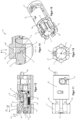
- the Figure 1 shows detail 29 of the view in Figure 2 , where further details of the invention can be found.
- the bolt head 1 can therefore be removed forwards in the direction of arrow 18 in the firing direction when the ejection opening 47 is released by moving the bolt slide 46 in the direction of arrow 18'.
- the ejection opening 47 is free, and the left boundary of the ejection opening 47 is formed by the wall of the barrel receiver 30, while the right boundary is at least partially formed by the receiver sleeve 8, so that the bolt head 1 can be removed from this free space, preferably without tools, by actuating a locking button to be explained later.
- FIGS. 6 to 10 show the locked state of the bolt head 1 in a receiving sleeve 8, which is part of the bolt slide 46, whereby it is pointed out that the bolt slide 46 according to Figure 4 is guided in a weapon-side bolt guide 25, which represents the slide guide for the bolt slide 46.
- the bolt housing 32 can be moved as part of the bolt slide 46 under the stock back 42, which significantly shortens the usable length of the weapon. This allows a shorter buttstock 40 to be realized because the bolt slide 46 with its bolt guide 25 extends under the stock back 42 in the open position. This improves the maneuverability of the weapon.
- the locking position for the bolt head 1 is characterized in that the bolt head 1 is spring-loaded locked in the receiving sleeve 8 by means of a spring-loaded locking button.
- this locking button is designed as an extractor 2, which means that the extractor 2 has a dual function, because firstly it serves to extract the cartridge from the cartridge chamber and secondly the extractor 2 preferably serves as a two-armed locking lever for the locking of the bolt head 1 in the receiving sleeve 8.
- the extractor 2 which is designed as a two-armed lever, is provided with an actuating surface 19 on its front lever arm and by grasping this actuating surface with a finger, it can be lifted in the area of the extractor groove 19a in the direction of the arrow 12.
- the opposite end of the lever engages with its nose, which is extended in the axial direction, in an associated receiving groove on a locking wedge 5.
- the actuation takes place by a downward pressure. This takes place against the force of a locking spring 10, which is in Figure 8 is shown.
- the locking spring 20 presses the lever end of the extractor 2 upwards, specifically in the direction 13', whereby the locking position of the locking wedge 5 in the receiving sleeve 8 on the bolt side in the locking groove 28 is spring-loaded, maintained and remains secured even in the event of vibrations in order to avoid unintentional displacement in the locked state.
- the entire locking device for actuating the bolt head 1 is arranged in the bolt head itself and is thus removed when the bolt head 1 is removed.
- the extractor 2 is accommodated with its pivot axis 3 in the bolt head 1, so that when the actuating surface 19 is actuated in the direction of arrow 12, the locking wedge 5 is moved downwards in the direction of arrow 13. This is the unlocked position, which in the Figures 11 to 15 is shown.
- the number 9 represents the firing pin bore 9 through which the firing pin passes centrally through the bolt head 1.
- the helical compression spring 14 is the ejector spring 14 for the ejector 10.
- the pin-shaped ejector 10 due to the spring force of the spring 14, ejects the cartridge held in the area of the bolt head 1 from the rear after the bolt slide or the chamber has been opened, whereby the cartridge is held in the extractor 2.
- reference number 4 shows a groove extending in the longitudinal direction of the locking head 1, in the area of which the two-armed extractor 2 is spring-loaded.
- the nose of the extractor 2 engages in an associated driving groove 6 in the area of the locking wedge 5.
- the reference number 7 indicates the driving lug of the extractor 2, which engages in the driving groove 6 of the locking wedge 5.
- a bolt handle receiving bore 17 is arranged, into which the bolt handle 31 engages in order to enable the entire sliding guide for the repeating process and the sliding of the entire unit on the bolt housing 32 and bolt slide 46 in the bolt guide 25.
- locking lugs 11 are arranged in a plane that are directed axially forwards and spaced apart from one another, forming gaps between them that are evenly distributed around the circumference. These locking lugs 11 lock the bolt head 1 in the barrel receiver 30 (monoblock) and transfer the load of the gas charge to the bolt.
- Figure 11 shows the top view of the unlocked bolt head 1 in the receiving sleeve 8, and the Figures 12 to 15 show the unlocked position. It can be seen that the actuating surface 19 is raised against the spring force of the locking springs 20, whereby according to Figure 22 In a preferred embodiment, the locking springs 20 are arranged in pairs.
- ejector spring 14 is mounted in an ejector bore 15 which is part of the bolt head 1.
- a firing pin lock can also be arranged in the interior of the bolt head 1, which can be manually operated via a hand-operated button (not shown).
- a driving surface 21 is formed on the front side at the rear of the cylindrical circumference of the receiving shaft 23 and a locking groove 28 for the engagement of the locking wedge 5 is arranged in the area of the receiving shaft 23.
- the receiving sleeve 8 forms a cylindrical receiving bore 24 into which the also cylindrical locking head 1 is inserted centrally.
- the cylindrical receiving shaft 23 therefore fits flush into the associated receiving bore 24 in the area of the receiving sleeve 8.
- the locking or latching of the bolt head 1 in the receiving sleeve 8 of the bolt slide 46 according to the invention is not exposed to great impact forces, but only serves to simply lock and secure the position of the bolt head 1 in the receiving housing 8.
- the locking force only has to be sufficient to pull the fired cartridge out of the cartridge chamber and eject it from the ejection opening 47.
- the receiving sleeve 8 is also held in the lock housing 32 in a rotationally secured manner.
- the asymmetrical rotation lock 44 in the form of an asymmetrical projection which engages in an associated groove in the lock housing 32 serves this purpose, so that the receiving sleeve 8 is also held in the lock housing in a rotationally secured manner.
- FIGS. 21 and 22 show the locked position of the bolt head 1 with the locking springs 20, preferably arranged in pairs, which act with a high holding force on the locking wedge 5 and hold it in the radial direction in the locking groove 22 in the receiving sleeve 8 in order to avoid undesired actuation of the lock when firing.
- FIGS. 23 to 26 show embodiments not covered by the claims, which schematically illustrate that instead of a single radially directed, spring-loaded locking with a locking wedge 5, there are also other releasable and lockable fastenings for the locking head 1 in the receiving sleeve 8.
- the bolt head 1 can also be operated from the front in the open ejection opening 47 in these embodiments in order to be able to easily remove and replace it without removing the bolt slide 46 or the chamber from the weapon.
- a ball cage can also be present in which a number of balls are evenly distributed around the circumference, which balls are pressed in the circumferential direction from the outside with a spring band 50 radially inwards into an associated circumferential annular groove 51 in the region of the receiving shaft 23.
- This spring-loaded ball catch can be triggered and released by pressure and/or impact on the bolt head 1.
- the extractor 2 then only serves to extract the cartridge, but does not have a dual function as in the first-mentioned embodiment.
- the actuation of the locking device with the locking wedge 5 can also be carried out by a separate locking button, whereby the dual function of the extractor 2 is not used.
- the extractor 2 would be present as a first part and next to it there is a separate button, which is not shown here, which actuates the spring-loaded locking wedge 5.
- Figure 24 It can be provided that the receiving shaft 23 is fixed with a threaded screw connection 48 or a bayonet screw connection 52 in an associated internal receptacle in the area of the receiving sleeve 8, whereby with such a type of fixing it only has to be ensured that a positionally and rotationally secured assignment of the locking head 1 to the receiving sleeve 8 is guaranteed.
- the invention is therefore not limited to the detachable actuation of the bolt head 1 by means of the extractor 2, but other embodiments within the scope of claim 1 can be used, all of which enable the bolt head 1 to be actuated from the front, easily removed from the opened ejection opening 47 and reinserted and fastened.
Landscapes
- Engineering & Computer Science (AREA)
- General Engineering & Computer Science (AREA)
- Toys (AREA)
Claims (14)
- Arme de chasse ou de sport comprenant une culasse constituée de plusieurs groupes de montage, qui appartient au groupe des culasses cylindriques ou à mouvement rectiligne ou rotatives, qui est constituée d'au moins un percuteur ou d'un support-percuteur, d'un ressort de percuteur, d'un extracteur (2) et d'une tête de culasse (1), dans laquelle la tête de culasse (1) est reçue de manière interchangeable avec un moyen de retenue dans une douille de réception (8) côté culasse qui est fixée dans un chariot de culasse (46) pouvant être bloqué et déplacé le long de l'arme, dans laquelle la tête de culasse (1) est librement accessible par l'avant lors du déplacement du chariot de culasse (46) dans une ouverture d'éjection (47) alors libérée au moins dans la direction de tir et peut être retirée ou fixée depuis la douille de réception (8) côté culasse, caractérisée en ce qu'une touche de verrouillage (2) agencée dans la tête de culasse (1) et actionnable manuellement depuis le côté avant de la tête de culasse (1) coopère avec un coin de verrouillage (5) qui est agencé de manière radialement mobile dans la tête de culasse (1) et établit un verrouillage entre le pourtour intérieur de la douille de réception (8) et le pourtour extérieur de la tête de culasse (1).
- Arme de chasse ou de sport selon la revendication 1, caractérisée en ce que le montage et/ou le démontage de la tête de culasse (1) sont effectués sans outil.
- Arme de chasse ou de sport selon la revendication 1 ou 2, caractérisée en ce que la touche de verrouillage actionnant la tête de culasse (1) fait partie de l'extracteur (2).
- Arme de chasse ou de sport selon la revendication 3, caractérisée en ce que la touche de verrouillage est réalisée sous la forme d'un levier à deux bras en tant que partie de l'éjecteur (2).
- Arme de chasse ou de sport selon l'une des revendications 1 à 4, caractérisée en ce que le coin de verrouillage (5) est sollicité par ressort et établit le verrouillage entre le pourtour intérieur de la douille de réception (8) et le pourtour extérieur de la tête de culasse (1) dans la position de fermeture de la tête de culasse (1).
- Arme de chasse ou de sport selon l'une des revendications 1 à 5, caractérisée en ce qu'un magasin est agencé au-dessus d'une poignée pistolet (39) et de manière affleurante l'ouverture d'éjection (47) dans un boîtier de système (33).
- Arme de chasse ou de sport selon la revendication 6, caractérisée en ce que le magasin est agencé avant la poignée pistolet (39) dans la direction de tir, au-dessus d'un pontet (37), et que l'ouverture d'éjection (47) est agencée au-dessus du pontet (37).
- Arme de chasse ou de sport selon la revendication 7, caractérisée en ce que le magasin est agencé avant le pontet (37) dans la direction de tir, et que l'ouverture d'éjection (47) est agencée au-dessus du magasin.
- Arme de chasse ou de sport selon l'une des revendications 1 à 7, caractérisée en ce que le chariot de culasse (46) vient en prise avec la tête de culasse (1) dirigée vers l'avant depuis le côté de la crosse (40, 41, 42) dans l'ouverture d'éjection (47) et la tête de culasse (1) peut être retirée de sa douille de réception (8) dans le chariot de culasse (46).
- Arme de chasse ou de sport selon l'une des revendications 1 à 8, caractérisée en ce que pour raccourcir la longueur d'une crosse arrière (40), un boîtier de culasse (32) est mobile sous un dos de crosse (42) en tant que partie du chariot de culasse (46).
- Arme de chasse ou de sport selon l'une des revendications 1 à 9, caractérisée en ce qu'un ressort d'éjecteur (14) est agencé dans un alésage d'éjecteur de la tête de culasse (1).
- Arme de chasse ou de sport selon l'une des revendications 1 à 10, caractérisée en ce qu'un verrou de percuteur est agencé dans la tête de culasse (1).
- Arme de chasse ou de sport selon l'une des revendications 1 à 11, caractérisée en ce qu'un réglage sans possibilité de rotation est présent entre la tête de culasse (1) et le boîtier de réception (8) côté arme.
- Arme de chasse ou de sport selon l'une des revendications 1 à 12, caractérisée en ce que la douille de réception (8) est aussi reçue dans le boîtier de culasse (32) sans pouvoir tourner.
Priority Applications (2)
| Application Number | Priority Date | Filing Date | Title |
|---|---|---|---|
| EP22162494.3A EP4246082B1 (fr) | 2022-03-16 | 2022-03-16 | Tête de coulasse d'un arme de chasse ou de sport |
| PCT/EP2023/056469 WO2023174929A1 (fr) | 2022-03-16 | 2023-03-14 | Tête de culasse d'arme de chasse et de sport |
Applications Claiming Priority (1)
| Application Number | Priority Date | Filing Date | Title |
|---|---|---|---|
| EP22162494.3A EP4246082B1 (fr) | 2022-03-16 | 2022-03-16 | Tête de coulasse d'un arme de chasse ou de sport |
Publications (3)
| Publication Number | Publication Date |
|---|---|
| EP4246082A1 EP4246082A1 (fr) | 2023-09-20 |
| EP4246082C0 EP4246082C0 (fr) | 2025-02-26 |
| EP4246082B1 true EP4246082B1 (fr) | 2025-02-26 |
Family
ID=80785086
Family Applications (1)
| Application Number | Title | Priority Date | Filing Date |
|---|---|---|---|
| EP22162494.3A Active EP4246082B1 (fr) | 2022-03-16 | 2022-03-16 | Tête de coulasse d'un arme de chasse ou de sport |
Country Status (2)
| Country | Link |
|---|---|
| EP (1) | EP4246082B1 (fr) |
| WO (1) | WO2023174929A1 (fr) |
Families Citing this family (2)
| Publication number | Priority date | Publication date | Assignee | Title |
|---|---|---|---|---|
| EP4703670A1 (fr) * | 2024-08-27 | 2026-03-04 | Daniel Dentler | Arme de sport et de chasse avec guide de culasse |
| EP4703671A1 (fr) | 2024-08-27 | 2026-03-04 | Daniel Dentler | Arme de chasse ou de sport avec crosse de serrage et guidage coulissant ajustables et ajustables et amovibles |
Family Cites Families (4)
| Publication number | Priority date | Publication date | Assignee | Title |
|---|---|---|---|---|
| DE3906496A1 (de) * | 1989-03-01 | 1990-09-20 | Karl K Mayer | Jagdbuechse mit gezogenem lauf und zylinder-verschluss, fuer den kugelschuss |
| US20100307042A1 (en) * | 2009-06-05 | 2010-12-09 | Michael Brent Jarboe | Modular firearm stock system |
| EP2634520B1 (fr) * | 2012-02-28 | 2014-09-17 | Dikar S. Coop. Ltda | Ensemble culasse pour fusil à répétition avec tête de culasse détachable et dispositif d'impossibilité de montage de l'ensemble de culasse sans sa tête dans le fusil |
| US10533816B2 (en) * | 2017-01-11 | 2020-01-14 | Q, Llc | Bolt assembly for firearms and methods of manufacture and clearing a cartridge thereof |
-
2022
- 2022-03-16 EP EP22162494.3A patent/EP4246082B1/fr active Active
-
2023
- 2023-03-14 WO PCT/EP2023/056469 patent/WO2023174929A1/fr not_active Ceased
Also Published As
| Publication number | Publication date |
|---|---|
| WO2023174929A1 (fr) | 2023-09-21 |
| EP4246082C0 (fr) | 2025-02-26 |
| EP4246082A1 (fr) | 2023-09-20 |
Similar Documents
| Publication | Publication Date | Title |
|---|---|---|
| DE1303061C2 (de) | Verwandelbare feuerwaffe | |
| EP1147359B1 (fr) | Culasse pour arme a feu de poing | |
| EP1830152B1 (fr) | Chargeur enfichable pour arme à feu | |
| DE19600459A1 (de) | Verschluß für eine Schußwaffe | |
| EP4028710B1 (fr) | Arme à feu | |
| DE20319451U1 (de) | Schußwaffe | |
| EP3372942B1 (fr) | Arme à feu de poing à chargement automatique verrouillable | |
| EP4246082B1 (fr) | Tête de coulasse d'un arme de chasse ou de sport | |
| DE102009057866B4 (de) | Handfeuerwaffe | |
| EP4455600A1 (fr) | Arme de chasse ou de sport a boitier compact de commande de chambre | |
| DE3521800C2 (de) | Lauf-Wechselsystem für eine Pistole | |
| DE102005036251B3 (de) | Schnellfeuergewehr und Umrüstverfahren | |
| DE102018114381B4 (de) | Repetiergewehr | |
| DE1478944A1 (de) | Explosiv betaetigtes Treibwerkzeug fuer Befestigungsmittel | |
| AT393028B (de) | Gasentnahmesystem fuer eine feuerwaffe | |
| AT525581B1 (de) | Verschluss für ein geradezug-repetiergewehr | |
| EP4070027B1 (fr) | Système de culasse | |
| EP0428525B1 (fr) | Arme a feu | |
| DE19903326C1 (de) | Anordnung zum Öffnen der Staubklappen einer Handfeuerwaffe | |
| DE90430C (fr) | ||
| DE102019135856B4 (de) | Schusswaffe | |
| DE102006005429B4 (de) | Verschluss-Einrast-Vorrichtung | |
| EP3754287B1 (fr) | Pistolet à canon rigide, en particulier pistolet d'entraînement | |
| DE102006036437B4 (de) | Lauf einer Handfeuerwaffe | |
| DE159157C (fr) |
Legal Events
| Date | Code | Title | Description |
|---|---|---|---|
| PUAI | Public reference made under article 153(3) epc to a published international application that has entered the european phase |
Free format text: ORIGINAL CODE: 0009012 |
|
| STAA | Information on the status of an ep patent application or granted ep patent |
Free format text: STATUS: THE APPLICATION HAS BEEN PUBLISHED |
|
| AK | Designated contracting states |
Kind code of ref document: A1 Designated state(s): AL AT BE BG CH CY CZ DE DK EE ES FI FR GB GR HR HU IE IS IT LI LT LU LV MC MK MT NL NO PL PT RO RS SE SI SK SM TR |
|
| STAA | Information on the status of an ep patent application or granted ep patent |
Free format text: STATUS: REQUEST FOR EXAMINATION WAS MADE |
|
| 17P | Request for examination filed |
Effective date: 20231128 |
|
| RBV | Designated contracting states (corrected) |
Designated state(s): AL AT BE BG CH CY CZ DE DK EE ES FI FR GB GR HR HU IE IS IT LI LT LU LV MC MK MT NL NO PL PT RO RS SE SI SK SM TR |
|
| STAA | Information on the status of an ep patent application or granted ep patent |
Free format text: STATUS: EXAMINATION IS IN PROGRESS |
|
| 17Q | First examination report despatched |
Effective date: 20240322 |
|
| GRAP | Despatch of communication of intention to grant a patent |
Free format text: ORIGINAL CODE: EPIDOSNIGR1 |
|
| STAA | Information on the status of an ep patent application or granted ep patent |
Free format text: STATUS: GRANT OF PATENT IS INTENDED |
|
| INTG | Intention to grant announced |
Effective date: 20240904 |
|
| GRAS | Grant fee paid |
Free format text: ORIGINAL CODE: EPIDOSNIGR3 |
|
| GRAA | (expected) grant |
Free format text: ORIGINAL CODE: 0009210 |
|
| STAA | Information on the status of an ep patent application or granted ep patent |
Free format text: STATUS: THE PATENT HAS BEEN GRANTED |
|
| AK | Designated contracting states |
Kind code of ref document: B1 Designated state(s): AL AT BE BG CH CY CZ DE DK EE ES FI FR GB GR HR HU IE IS IT LI LT LU LV MC MK MT NL NO PL PT RO RS SE SI SK SM TR |
|
| REG | Reference to a national code |
Ref country code: GB Ref legal event code: FG4D Free format text: NOT ENGLISH |
|
| REG | Reference to a national code |
Ref country code: CH Ref legal event code: EP |
|
| REG | Reference to a national code |
Ref country code: DE Ref legal event code: R096 Ref document number: 502022002987 Country of ref document: DE |
|
| REG | Reference to a national code |
Ref country code: IE Ref legal event code: FG4D Free format text: LANGUAGE OF EP DOCUMENT: GERMAN |
|
| PGFP | Annual fee paid to national office [announced via postgrant information from national office to epo] |
Ref country code: AT Payment date: 20250417 Year of fee payment: 4 |
|
| U01 | Request for unitary effect filed |
Effective date: 20250324 |
|
| U07 | Unitary effect registered |
Designated state(s): AT BE BG DE DK EE FI FR IT LT LU LV MT NL PT RO SE SI Effective date: 20250328 |
|
| U20 | Renewal fee for the european patent with unitary effect paid |
Year of fee payment: 4 Effective date: 20250516 |
|
| PG25 | Lapsed in a contracting state [announced via postgrant information from national office to epo] |
Ref country code: RS Free format text: LAPSE BECAUSE OF FAILURE TO SUBMIT A TRANSLATION OF THE DESCRIPTION OR TO PAY THE FEE WITHIN THE PRESCRIBED TIME-LIMIT Effective date: 20250526 |
|
| PG25 | Lapsed in a contracting state [announced via postgrant information from national office to epo] |
Ref country code: PL Free format text: LAPSE BECAUSE OF FAILURE TO SUBMIT A TRANSLATION OF THE DESCRIPTION OR TO PAY THE FEE WITHIN THE PRESCRIBED TIME-LIMIT Effective date: 20250226 |
|
| PG25 | Lapsed in a contracting state [announced via postgrant information from national office to epo] |
Ref country code: ES Free format text: LAPSE BECAUSE OF FAILURE TO SUBMIT A TRANSLATION OF THE DESCRIPTION OR TO PAY THE FEE WITHIN THE PRESCRIBED TIME-LIMIT Effective date: 20250226 |
|
| PG25 | Lapsed in a contracting state [announced via postgrant information from national office to epo] |
Ref country code: IS Free format text: LAPSE BECAUSE OF FAILURE TO SUBMIT A TRANSLATION OF THE DESCRIPTION OR TO PAY THE FEE WITHIN THE PRESCRIBED TIME-LIMIT Effective date: 20250626 Ref country code: NO Free format text: LAPSE BECAUSE OF FAILURE TO SUBMIT A TRANSLATION OF THE DESCRIPTION OR TO PAY THE FEE WITHIN THE PRESCRIBED TIME-LIMIT Effective date: 20250526 |
|
| PG25 | Lapsed in a contracting state [announced via postgrant information from national office to epo] |
Ref country code: HR Free format text: LAPSE BECAUSE OF FAILURE TO SUBMIT A TRANSLATION OF THE DESCRIPTION OR TO PAY THE FEE WITHIN THE PRESCRIBED TIME-LIMIT Effective date: 20250226 |
|
| PG25 | Lapsed in a contracting state [announced via postgrant information from national office to epo] |
Ref country code: GR Free format text: LAPSE BECAUSE OF FAILURE TO SUBMIT A TRANSLATION OF THE DESCRIPTION OR TO PAY THE FEE WITHIN THE PRESCRIBED TIME-LIMIT Effective date: 20250527 |
|
| PG25 | Lapsed in a contracting state [announced via postgrant information from national office to epo] |
Ref country code: SM Free format text: LAPSE BECAUSE OF FAILURE TO SUBMIT A TRANSLATION OF THE DESCRIPTION OR TO PAY THE FEE WITHIN THE PRESCRIBED TIME-LIMIT Effective date: 20250226 |
|
| PG25 | Lapsed in a contracting state [announced via postgrant information from national office to epo] |
Ref country code: CZ Free format text: LAPSE BECAUSE OF FAILURE TO SUBMIT A TRANSLATION OF THE DESCRIPTION OR TO PAY THE FEE WITHIN THE PRESCRIBED TIME-LIMIT Effective date: 20250226 |
|
| REG | Reference to a national code |
Ref country code: CH Ref legal event code: H13 Free format text: ST27 STATUS EVENT CODE: U-0-0-H10-H13 (AS PROVIDED BY THE NATIONAL OFFICE) Effective date: 20251024 |
|
| PG25 | Lapsed in a contracting state [announced via postgrant information from national office to epo] |
Ref country code: SK Free format text: LAPSE BECAUSE OF FAILURE TO SUBMIT A TRANSLATION OF THE DESCRIPTION OR TO PAY THE FEE WITHIN THE PRESCRIBED TIME-LIMIT Effective date: 20250226 |
|
| PG25 | Lapsed in a contracting state [announced via postgrant information from national office to epo] |
Ref country code: MC Free format text: LAPSE BECAUSE OF FAILURE TO SUBMIT A TRANSLATION OF THE DESCRIPTION OR TO PAY THE FEE WITHIN THE PRESCRIBED TIME-LIMIT Effective date: 20250226 |
|
| PLBE | No opposition filed within time limit |
Free format text: ORIGINAL CODE: 0009261 |
|
| STAA | Information on the status of an ep patent application or granted ep patent |
Free format text: STATUS: NO OPPOSITION FILED WITHIN TIME LIMIT |
|
| PG25 | Lapsed in a contracting state [announced via postgrant information from national office to epo] |
Ref country code: CH Free format text: LAPSE BECAUSE OF NON-PAYMENT OF DUE FEES Effective date: 20250331 |
|
| PG25 | Lapsed in a contracting state [announced via postgrant information from national office to epo] |
Ref country code: IE Free format text: LAPSE BECAUSE OF NON-PAYMENT OF DUE FEES Effective date: 20250316 |
|
| 26N | No opposition filed |
Effective date: 20251127 |