EP4246154A1 - System und verfahren zur fehlererkennung in mittelspannungsschaltungen - Google Patents
System und verfahren zur fehlererkennung in mittelspannungsschaltungen Download PDFInfo
- Publication number
- EP4246154A1 EP4246154A1 EP20823887.3A EP20823887A EP4246154A1 EP 4246154 A1 EP4246154 A1 EP 4246154A1 EP 20823887 A EP20823887 A EP 20823887A EP 4246154 A1 EP4246154 A1 EP 4246154A1
- Authority
- EP
- European Patent Office
- Prior art keywords
- fault
- med
- grounding
- cable
- grounding conductor
- Prior art date
- Legal status (The legal status is an assumption and is not a legal conclusion. Google has not performed a legal analysis and makes no representation as to the accuracy of the status listed.)
- Granted
Links
Images


Classifications
-
- G—PHYSICS
- G01—MEASURING; TESTING
- G01R—MEASURING ELECTRIC VARIABLES; MEASURING MAGNETIC VARIABLES
- G01R31/00—Arrangements for testing electric properties; Arrangements for locating electric faults; Arrangements for electrical testing characterised by what is being tested not provided for elsewhere
- G01R31/08—Locating faults in cables, transmission lines, or networks
- G01R31/081—Locating faults in cables, transmission lines, or networks according to type of conductors
- G01R31/083—Locating faults in cables, transmission lines, or networks according to type of conductors in cables, e.g. underground
-
- G—PHYSICS
- G01—MEASURING; TESTING
- G01R—MEASURING ELECTRIC VARIABLES; MEASURING MAGNETIC VARIABLES
- G01R31/00—Arrangements for testing electric properties; Arrangements for locating electric faults; Arrangements for electrical testing characterised by what is being tested not provided for elsewhere
- G01R31/08—Locating faults in cables, transmission lines, or networks
- G01R31/088—Aspects of digital computing
-
- Y—GENERAL TAGGING OF NEW TECHNOLOGICAL DEVELOPMENTS; GENERAL TAGGING OF CROSS-SECTIONAL TECHNOLOGIES SPANNING OVER SEVERAL SECTIONS OF THE IPC; TECHNICAL SUBJECTS COVERED BY FORMER USPC CROSS-REFERENCE ART COLLECTIONS [XRACs] AND DIGESTS
- Y04—INFORMATION OR COMMUNICATION TECHNOLOGIES HAVING AN IMPACT ON OTHER TECHNOLOGY AREAS
- Y04S—SYSTEMS INTEGRATING TECHNOLOGIES RELATED TO POWER NETWORK OPERATION, COMMUNICATION OR INFORMATION TECHNOLOGIES FOR IMPROVING THE ELECTRICAL POWER GENERATION, TRANSMISSION, DISTRIBUTION, MANAGEMENT OR USAGE, i.e. SMART GRIDS
- Y04S10/00—Systems supporting electrical power generation, transmission or distribution
- Y04S10/50—Systems or methods supporting the power network operation or management, involving a certain degree of interaction with the load-side end user applications
- Y04S10/52—Outage or fault management, e.g. fault detection or location
Definitions
- the object of the present invention is a method and system for detecting faults in insulated electric power distribution cables.
- Some of the already known methods refer to the detection of pressure or acoustic waves when applying a current pulse on the cable, to the generation of an electric arc through the direct application of high voltage to the cable, reflections of high frequency waves, etc.
- these power distribution cables (101) are made of an electrical conductor (101), through which the electric power flows, and by different layers that are added coaxially to the main conductor until reaching a cover (103).
- One of the layers of these cables is the screen or mesh (102), which is also made of conductive material and is used as a ground terminal, that is, it is connected to grounding systems.
- the time that elapses, from the moment a fault is generated and the network is left without service, until the service is restored be as short as possible.
- This time is made up of three main components: the travel time of the personnel performing the repair, the fault location time and the fault repair time.
- the main objective of the fault detection method and system according to the present invention is to reduce the fault location time in medium voltage cables, thus improving the service quality index of the network operator.
- the method according to the present invention differs from the methods based on the continuous monitoring of the power lines and from the methods based on the generation of an excitation signal after the fault occurs.
- the method according to the present invention is based on the continuous monitoring of the current that flows through the grounding conductor that connects the metallic structures of the transformer of the transformation centers with the grounding system.
- the present invention relates to a method for locating faults in electric power distribution cables, the method is applied to a medium voltage circuit comprising at least one electric power distribution cable, a first transformation center comprising a first transformer and a first grounding conductor, a first grounding system comprising a first grounding resistor connected to the first transformer through the first grounding conductor.
- the first transformation center is connected to a first end of the cable.
- the medium voltage circuit also comprises a second transformation center comprising a second transformer and a second grounding conductor, a second grounding system comprising a second grounding resistor connected to the second transformer through the second grounding conductor.
- the second transformation center is connected to a second end of the cable.
- the method also comprises identifying the location of the fault based on the distances d 1 and d 2.
- This method uses comparative measurements from sensor devices distributed in each of the transformation centers that are part of the circuit to be monitored. This method has the advantage of detecting and locating the fault in real time in an unattended way and without intervention, using compact devices that do not require the necessary insulation to monitor medium voltage lines, so their volume is substantially reduced.
- the present invention relates to a fault detection system for a medium voltage circuit that comprises sets of electric power distribution cables, a first transformation center that comprises a first transformer and a first grounding conductor and a first grounding system comprising a first grounding resistor connected to the first transformer through the first grounding conductor.
- the first transformation center is connected to a first end of the cable.
- the medium voltage circuit further comprises a second transformation center comprising a second transformer and a second grounding conductor, a second grounding system comprising a second grounding resistor connected to the second transformer through the second grounding conductor.
- the second transformation center is connected to a second end of the cable.
- the fault detection system comprises a set of sensors comprising wireless communication means and a processing unit, wherein a first sensor comprises means for connecting to the first grounding conductor and is configured to detect a cable fault by detecting a threshold current value through the first grounding conductor.
- a first sensor comprises means for connecting to the first grounding conductor and is configured to detect a cable fault by detecting a threshold current value through the first grounding conductor.
- the first sensor is configured to measure a first current value I med1 through the first grounding conductor, obtain the value of the first resistor and transmit I med1 and to the processing unit.
- a second sensor comprises means for connecting to the second grounding conductor, and is configured to detect a cable fault by detecting a threshold current value through the second grounding conductor.
- the second sensor is configured to measure a second current value I med2 through the second grounding conductor, obtain the value of the second resistor and transmit I med2 and to the processing unit.
- Figure 2 represents a medium voltage circuit (200) in a ring configuration with a plurality of cables (205), fed by the outlet of a substation (201) and having four transformation centers (210, 220, 230, 240) as part of the fault detection system.
- Each transformation center (210, 220, 230, 240) is associated with a grounding system, represented in the following figure by grounding resistors (RPAT1-4) and by a grounding conductor (603) of the transformer that allows connecting the metal elements of the transformer of the transformation center (210, 220, 230, 240) to the grounding system represented by (RPAT1-4).
- RPAT1-4 grounding resistors
- 603 grounding conductor
- a first transformation center (210) can be seen that comprises a first transformer and a first grounding resistor (RPAT1) as part of a first grounding system connected to the first transformation center (210).
- the first transformation center (210) is in turn connected to a first end of the cable (205).
- the grounding conductor (603) of the transformer allows the metal elements of the transformer of the transformation center (210) to be connected to the grounding system represented by the resistor (RPAT1).
- the fault detection system comprises a second transformation center (220) comprising a second transformer and a second grounding resistor (RPAT2) as part of a second grounding system connected to the second transformer through the grounding conductor (603).
- the second transformation center (220) is in turn connected to a second end of the cable (205).
- the current through the grounding conductor of the transformer is only a few milliamps.
- a conductive path is generated between the main conductor of the cable (205) and its mesh, so that portion of the electric power passes through the cable mesh (205) heading towards the two ends of the cable (205), whose mesh is connected to the grounding systems with resistors (RPAT1, RPAT2) connected to the two transformation centers (210, 220) that are at the ends of the cable (205), generating an increase in the value of the current in the grounding conductor (603) of the transformer in the transformation centers (210, 220).
- the impedance that "sees" the current in each of the two directions shall determine the amount of current flowing in each direction.
- the value of the current flowing in each direction shall depend on the value of the fault current and other parameters such as the network configuration, the length of the cables, the neutral regime, the type of fault, the location in which the fault has occurred and the grounding resistor values of the grounding systems of each of the transformation centers.
- a fault current I fault will be produced, which will bifurcate in two opposite directions, towards the two transformation centers (210, 220) that are at the ends of the cable.
- L1, R1, C1, L2, R2, and C2 are defined by the values of distributed impedance of the cable (205) (L, R and C, whose values are provided by the cable manufacturer) multiplied by the value in meters, of the distance from the point where the fault occurs to the first transformation center (210) ( d 1) or the second transformation center (220) ( d 2), in this way, the following ratios are obtained:
- L 1 H L H m ⁇ d 1 m
- R 1 ⁇ R ⁇ m ⁇ d 1 m
- C 1 F C F m ⁇ d 1 m
- L 2 H L H m ⁇ d 2 m
- R 2 ⁇ R ⁇ m ⁇ d 2 m
- C 2 F C F m ⁇ d 2 m
- I med 1 V x R PAT 1 ⁇ 1 ⁇ CL ⁇ 2 d 1 2 + RCj ⁇ d 1 2 + Lj ⁇ d 1 + Rd 1
- I med 2 V x R PAT 2 ⁇ 1 ⁇ CL ⁇ 2 d 2 2 + RCj ⁇ d 2 2 + Lj ⁇ d 2 + Rd 2
- I med 1 I med 2 R PAT 2 + Lj ⁇ d 2 + Rd 2
- R PAT 1 + Lj ⁇ d 1 + Rd 1 R PAT 2 + d 2 ⁇ Lj ⁇ + R R PAT 1 + d 1 ⁇ Lj ⁇ + R
- d 2 I med 2 ⁇ 1 ⁇ K ⁇ R PAT 2 + I med 1 ⁇ 1 + K ⁇ R PAT 1 I med 2 + I med 1
- K lean be used, as a valid constant for most scenarios.
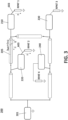
- Figure 5 shows the behavior of the fault current I fault (500) of a transient nature of the fault, which implies that, at the moment in which it occurs, there is an initial moment in which a high frequency transient phenomenon is generated, followed by a stationary period of time characterized by a signal at the frequency of the electrical network.
- the impedance that the grounding system has at the initial time represented in the figures by (RPAT1-4), where the frequency components of the transient current are high, will have the contribution of a resistive portion, but also of a reactive portion (capacitive, inductive or a combination of both) appreciable, so it is desirable to be able to determine the value of each of the portions R, L and C that constitute the grounding system in order to characterize the complete phenomenon and not just in steady state.
- One way to obtain these equivalents is by implementing a Bode diagram in magnitude and in phase, for which it is required to measure the value of the impedance and the phase shift between the voltage and the current at different frequencies (frequency sweep).
- the location method of the present invention may comprise means adapted to obtain and process other data from the network itself, such as those relating to the length or section of the cables, the type of insulation in each section, the path of the lines, the junction points, etc., to achieve a more exact model of the network and improve the location and identification of the fault.
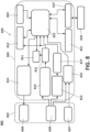
- the fault detection system (800) comprises: A set of distributed sensors (600), each installed by means of a transducer (602) in the grounding conductor (603) of each of the transformation centers (210, 220, 230, 240) of the circuit (200) to be monitored, wherein each distributed sensor (600) is configured to continuously monitor the current I med in said grounding conductor (603) and detect the fault in the cable (205) by current threshold, as well as determine the grounding resistor (RPAT1-4) at the moment in which the fault occurs in the cable (205), identifying the resistive portion and the reactive portion (L and C) using a frequency sweep to obtain a Bode diagram in magnitude and phase.
- each distributed sensor (600) is configured to continuously monitor the current I med in said grounding conductor (603) and detect the fault in the cable (205) by current threshold, as well as determine the grounding resistor (RPAT1-4) at the moment in which the fault occurs in the cable (205), identifying the resistive portion and the reactive portion (L and C) using a frequency
- each distributed sensor (600) is configured to store the data internally so that it can be transmitted remotely to a processing unit (818).
- Each distributed sensor (600) comprises wireless transmission means (819) for the remote sending of the data acquired by each sensor equipment (600) to a remote processing unit (18).
- Each distributed sensor (600) comprises a synchronization system (821) that allows the data from the different distributed sensors to have a single time base when processed.
- the system (800) comprises a processing unit (818) where the data is stored and grouped and where the analysis of the received data can be performed in real time to obtain the distance values d 1 and d 2.
- the system (800) comprises alert and display means, preferably an alarm system that may indicate to the user the fault condition and the approximate location of the fault from the measurements recorded by the sensor devices (600) and their analysis to obtain values of distance d 1 and d 2.
- alert and display means preferably an alarm system that may indicate to the user the fault condition and the approximate location of the fault from the measurements recorded by the sensor devices (600) and their analysis to obtain values of distance d 1 and d 2.
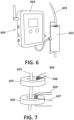
- FIG 6 shows an example of a distributed sensor (600) in accordance with the present invention.
- the sensor (600) comprises a transducer (602) through which the grounding conductor (603) of the transformer of one of the transformation centers runs.
- the electronics of said sensor device (600) is comprised in the containment housing (604).
- FIG 7 shows the transducer element (602) connected to the sensor (600).
- the transducer element (602) is formed by two toroidal magnetic cores (605) and (606) through which the grounding conductor (603) is passed, one of the cores (605) induces an electromotive force (emf) in the conductor to be monitored by means of a set of injection loops (608), while the other toroid (606) records the value of the current that said emf generates by the conductor by means of a set of measuring loops (609), which depends on the impedance of said conductor (603).
- An additional loop (607), wound on the measuring magnetic core (606), is also required to be able to determine the induced voltage in the conductor (603).
- Figure 8 shows parts of the system (800).
- figure 8 shows a distributed sensor (600), the transducer (602) as an interface element between the distributed sensor (600) and the grounding cable (603) as well as the processing unit (818) of the system (800).
- the distributed sensor (600) comprises:
Landscapes
- Physics & Mathematics (AREA)
- General Physics & Mathematics (AREA)
- Engineering & Computer Science (AREA)
- Mathematical Physics (AREA)
- Theoretical Computer Science (AREA)
- Locating Faults (AREA)
Applications Claiming Priority (1)
| Application Number | Priority Date | Filing Date | Title |
|---|---|---|---|
| PCT/ES2020/070691 WO2022101521A1 (es) | 2020-11-10 | 2020-11-10 | Sistema y procedimiento de detección de averías en circuitos de media tensión |
Publications (3)
| Publication Number | Publication Date |
|---|---|
| EP4246154A1 true EP4246154A1 (de) | 2023-09-20 |
| EP4246154B1 EP4246154B1 (de) | 2024-05-01 |
| EP4246154C0 EP4246154C0 (de) | 2024-05-01 |
Family
ID=73793230
Family Applications (1)
| Application Number | Title | Priority Date | Filing Date |
|---|---|---|---|
| EP20823887.3A Active EP4246154B1 (de) | 2020-11-10 | 2020-11-10 | System und verfahren zur fehlererkennung in mittelspannungsschaltungen |
Country Status (5)
| Country | Link |
|---|---|
| US (1) | US11933833B2 (de) |
| EP (1) | EP4246154B1 (de) |
| CN (1) | CN116601506B (de) |
| ES (1) | ES2984157T3 (de) |
| WO (1) | WO2022101521A1 (de) |
Families Citing this family (3)
| Publication number | Priority date | Publication date | Assignee | Title |
|---|---|---|---|---|
| ES3008709T3 (en) * | 2022-04-06 | 2025-03-24 | Lumiker Aplicaciones Tecnologicas S L | Method for locating a fault point on a high-voltage three-phase ac cable, and system for locating a fault point |
| CN117630613B (zh) * | 2024-01-25 | 2024-04-26 | 南京九维测控科技有限公司 | 一种基于接地环流拟合曲线的电缆绝缘故障定位方法 |
| CN120334800B (zh) * | 2025-06-18 | 2025-09-12 | 西安理工大学 | 一种基于d轴电流倍基频分量积分比的单相接地故障检测方法 |
Family Cites Families (8)
| Publication number | Priority date | Publication date | Assignee | Title |
|---|---|---|---|---|
| JP2010166769A (ja) * | 2009-01-19 | 2010-07-29 | Chugoku Electric Power Co Inc:The | 地絡距離継電装置 |
| JP2010164514A (ja) * | 2009-01-19 | 2010-07-29 | Chugoku Electric Power Co Inc:The | 故障点標定装置 |
| EP2330709B8 (de) * | 2009-12-02 | 2019-09-11 | ABB Schweiz AG | Erdungsfehler in Stromverteilungssystemen mit gemischten unter- und oberirdischen Stromleitungen |
| CN101846718B (zh) * | 2010-06-22 | 2012-12-19 | 山东电力研究院 | 一种电力系统配电网单相接地故障定位系统及其方法 |
| CN102879710B (zh) * | 2012-09-24 | 2015-02-18 | 吉林市简通电气科技有限公司 | 配电线路单相接地故障点检测系统和检测方法 |
| US20180233895A1 (en) * | 2017-02-16 | 2018-08-16 | Electrical Materials Company | Localized application of high impedance fault isolation in multi-tap electrical power distribution system |
| CN106972464B (zh) * | 2017-03-31 | 2018-12-18 | 广州供电局有限公司 | 一种同塔四回输电线路上的保护性能评估系统与方法 |
| CN108646144A (zh) * | 2018-07-25 | 2018-10-12 | 国家电网有限公司 | 一种高压单芯电缆短路故障离线测距方法、装置及系统 |
-
2020
- 2020-11-10 CN CN202080108002.6A patent/CN116601506B/zh active Active
- 2020-11-10 US US18/252,405 patent/US11933833B2/en active Active
- 2020-11-10 ES ES20823887T patent/ES2984157T3/es active Active
- 2020-11-10 EP EP20823887.3A patent/EP4246154B1/de active Active
- 2020-11-10 WO PCT/ES2020/070691 patent/WO2022101521A1/es not_active Ceased
Also Published As
| Publication number | Publication date |
|---|---|
| EP4246154B1 (de) | 2024-05-01 |
| EP4246154C0 (de) | 2024-05-01 |
| ES2984157T3 (es) | 2024-10-29 |
| US20230393186A1 (en) | 2023-12-07 |
| US11933833B2 (en) | 2024-03-19 |
| CN116601506B (zh) | 2025-09-26 |
| WO2022101521A1 (es) | 2022-05-19 |
| CN116601506A (zh) | 2023-08-15 |
Similar Documents
| Publication | Publication Date | Title |
|---|---|---|
| AU2022209344A1 (en) | Smart sensor network for power grid health monitoring | |
| EP4246154B1 (de) | System und verfahren zur fehlererkennung in mittelspannungsschaltungen | |
| US8219335B2 (en) | Electric winding displacement detection method and apparatus | |
| US9874591B2 (en) | Subsea deployed apparatus and method | |
| CN112534280A (zh) | 用于使用正序和负序电压变化来定位在多相电网上的故障的系统和方法 | |
| Loos et al. | Fault direction method in compensated network using the zero sequence active energy signal | |
| CN116754996A (zh) | 煤矿高压供电故障定位精准选线系统 | |
| KR20130028302A (ko) | 활선 전력케이블 절연상태 감시장치 및 방법 | |
| JP2001196980A (ja) | 有線式配電線遠方監視制御用通信ケーブルの障害点探査・標定方法および装置 | |
| CN106019063A (zh) | 故障指示器和故障检测方法 | |
| CN217739316U (zh) | 一种电缆线路交叉互联回路金属屏蔽电阻带电检测系统 | |
| JP2006200898A (ja) | 割込絶縁計測装置 | |
| JP2006200898A5 (de) | ||
| JP3657064B2 (ja) | 高圧絶縁常時監視装置 | |
| KR20080039570A (ko) | 열배관누수감지장치 및 그 방법 | |
| Rynjah et al. | Microcontroller-based Cable Fault and Insulation Flaw Detection in Low-Voltage Cables | |
| JP7420337B2 (ja) | 配電系統探査システム | |
| JP2001116714A (ja) | 塗覆装された埋設金属導体の損傷判定装置及び損傷判定方法 | |
| Atsever et al. | A Predictive Maintenance Approach for Non-Effectively Earthed Radial Distribution Networks | |
| CN117406017A (zh) | 一种用于电力配网故障定位的方法和装置 | |
| JPS6212878A (ja) | 一点接地系システムの地絡、短絡監視方式 | |
| JPH08116299A (ja) | 平衡ケーブルの故障位置特定方法 | |
| JPH0554913B2 (de) | ||
| JPS6212879A (ja) | 一点接地系システムの地絡監視方式 | |
| JPS6222565U (de) |
Legal Events
| Date | Code | Title | Description |
|---|---|---|---|
| STAA | Information on the status of an ep patent application or granted ep patent |
Free format text: STATUS: UNKNOWN |
|
| STAA | Information on the status of an ep patent application or granted ep patent |
Free format text: STATUS: THE INTERNATIONAL PUBLICATION HAS BEEN MADE |
|
| PUAI | Public reference made under article 153(3) epc to a published international application that has entered the european phase |
Free format text: ORIGINAL CODE: 0009012 |
|
| STAA | Information on the status of an ep patent application or granted ep patent |
Free format text: STATUS: REQUEST FOR EXAMINATION WAS MADE |
|
| 17P | Request for examination filed |
Effective date: 20230508 |
|
| AK | Designated contracting states |
Kind code of ref document: A1 Designated state(s): AL AT BE BG CH CY CZ DE DK EE ES FI FR GB GR HR HU IE IS IT LI LT LU LV MC MK MT NL NO PL PT RO RS SE SI SK SM TR |
|
| DAV | Request for validation of the european patent (deleted) | ||
| DAX | Request for extension of the european patent (deleted) | ||
| GRAP | Despatch of communication of intention to grant a patent |
Free format text: ORIGINAL CODE: EPIDOSNIGR1 |
|
| STAA | Information on the status of an ep patent application or granted ep patent |
Free format text: STATUS: GRANT OF PATENT IS INTENDED |
|
| GRAS | Grant fee paid |
Free format text: ORIGINAL CODE: EPIDOSNIGR3 |
|
| INTG | Intention to grant announced |
Effective date: 20240301 |
|
| GRAA | (expected) grant |
Free format text: ORIGINAL CODE: 0009210 |
|
| STAA | Information on the status of an ep patent application or granted ep patent |
Free format text: STATUS: THE PATENT HAS BEEN GRANTED |
|
| AK | Designated contracting states |
Kind code of ref document: B1 Designated state(s): AL AT BE BG CH CY CZ DE DK EE ES FI FR GB GR HR HU IE IS IT LI LT LU LV MC MK MT NL NO PL PT RO RS SE SI SK SM TR |
|
| REG | Reference to a national code |
Ref country code: GB Ref legal event code: FG4D |
|
| REG | Reference to a national code |
Ref country code: CH Ref legal event code: EP |
|
| REG | Reference to a national code |
Ref country code: IE Ref legal event code: FG4D |
|
| REG | Reference to a national code |
Ref country code: DE Ref legal event code: R096 Ref document number: 602020030335 Country of ref document: DE |
|
| U01 | Request for unitary effect filed |
Effective date: 20240531 |
|
| U07 | Unitary effect registered |
Designated state(s): AT BE BG DE DK EE FI FR IT LT LU LV MT NL PT SE SI Effective date: 20240612 |
|
| PG25 | Lapsed in a contracting state [announced via postgrant information from national office to epo] |
Ref country code: IS Free format text: LAPSE BECAUSE OF FAILURE TO SUBMIT A TRANSLATION OF THE DESCRIPTION OR TO PAY THE FEE WITHIN THE PRESCRIBED TIME-LIMIT Effective date: 20240901 |
|
| PG25 | Lapsed in a contracting state [announced via postgrant information from national office to epo] |
Ref country code: HR Free format text: LAPSE BECAUSE OF FAILURE TO SUBMIT A TRANSLATION OF THE DESCRIPTION OR TO PAY THE FEE WITHIN THE PRESCRIBED TIME-LIMIT Effective date: 20240501 |
|
| PG25 | Lapsed in a contracting state [announced via postgrant information from national office to epo] |
Ref country code: GR Free format text: LAPSE BECAUSE OF FAILURE TO SUBMIT A TRANSLATION OF THE DESCRIPTION OR TO PAY THE FEE WITHIN THE PRESCRIBED TIME-LIMIT Effective date: 20240802 |
|
| PG25 | Lapsed in a contracting state [announced via postgrant information from national office to epo] |
Ref country code: PL Free format text: LAPSE BECAUSE OF FAILURE TO SUBMIT A TRANSLATION OF THE DESCRIPTION OR TO PAY THE FEE WITHIN THE PRESCRIBED TIME-LIMIT Effective date: 20240501 |
|
| REG | Reference to a national code |
Ref country code: ES Ref legal event code: FG2A Ref document number: 2984157 Country of ref document: ES Kind code of ref document: T3 Effective date: 20241029 |
|
| PG25 | Lapsed in a contracting state [announced via postgrant information from national office to epo] |
Ref country code: PL Free format text: LAPSE BECAUSE OF FAILURE TO SUBMIT A TRANSLATION OF THE DESCRIPTION OR TO PAY THE FEE WITHIN THE PRESCRIBED TIME-LIMIT Effective date: 20240501 Ref country code: NO Free format text: LAPSE BECAUSE OF FAILURE TO SUBMIT A TRANSLATION OF THE DESCRIPTION OR TO PAY THE FEE WITHIN THE PRESCRIBED TIME-LIMIT Effective date: 20240801 Ref country code: IS Free format text: LAPSE BECAUSE OF FAILURE TO SUBMIT A TRANSLATION OF THE DESCRIPTION OR TO PAY THE FEE WITHIN THE PRESCRIBED TIME-LIMIT Effective date: 20240901 Ref country code: HR Free format text: LAPSE BECAUSE OF FAILURE TO SUBMIT A TRANSLATION OF THE DESCRIPTION OR TO PAY THE FEE WITHIN THE PRESCRIBED TIME-LIMIT Effective date: 20240501 Ref country code: GR Free format text: LAPSE BECAUSE OF FAILURE TO SUBMIT A TRANSLATION OF THE DESCRIPTION OR TO PAY THE FEE WITHIN THE PRESCRIBED TIME-LIMIT Effective date: 20240802 Ref country code: RS Free format text: LAPSE BECAUSE OF FAILURE TO SUBMIT A TRANSLATION OF THE DESCRIPTION OR TO PAY THE FEE WITHIN THE PRESCRIBED TIME-LIMIT Effective date: 20240801 |
|
| U20 | Renewal fee for the european patent with unitary effect paid |
Year of fee payment: 5 Effective date: 20241023 |
|
| PG25 | Lapsed in a contracting state [announced via postgrant information from national office to epo] |
Ref country code: CZ Free format text: LAPSE BECAUSE OF FAILURE TO SUBMIT A TRANSLATION OF THE DESCRIPTION OR TO PAY THE FEE WITHIN THE PRESCRIBED TIME-LIMIT Effective date: 20240501 |
|
| PG25 | Lapsed in a contracting state [announced via postgrant information from national office to epo] |
Ref country code: RO Free format text: LAPSE BECAUSE OF FAILURE TO SUBMIT A TRANSLATION OF THE DESCRIPTION OR TO PAY THE FEE WITHIN THE PRESCRIBED TIME-LIMIT Effective date: 20240501 Ref country code: SK Free format text: LAPSE BECAUSE OF FAILURE TO SUBMIT A TRANSLATION OF THE DESCRIPTION OR TO PAY THE FEE WITHIN THE PRESCRIBED TIME-LIMIT Effective date: 20240501 |
|
| PG25 | Lapsed in a contracting state [announced via postgrant information from national office to epo] |
Ref country code: SM Free format text: LAPSE BECAUSE OF FAILURE TO SUBMIT A TRANSLATION OF THE DESCRIPTION OR TO PAY THE FEE WITHIN THE PRESCRIBED TIME-LIMIT Effective date: 20240501 |
|
| PG25 | Lapsed in a contracting state [announced via postgrant information from national office to epo] |
Ref country code: SM Free format text: LAPSE BECAUSE OF FAILURE TO SUBMIT A TRANSLATION OF THE DESCRIPTION OR TO PAY THE FEE WITHIN THE PRESCRIBED TIME-LIMIT Effective date: 20240501 Ref country code: SK Free format text: LAPSE BECAUSE OF FAILURE TO SUBMIT A TRANSLATION OF THE DESCRIPTION OR TO PAY THE FEE WITHIN THE PRESCRIBED TIME-LIMIT Effective date: 20240501 Ref country code: RO Free format text: LAPSE BECAUSE OF FAILURE TO SUBMIT A TRANSLATION OF THE DESCRIPTION OR TO PAY THE FEE WITHIN THE PRESCRIBED TIME-LIMIT Effective date: 20240501 Ref country code: CZ Free format text: LAPSE BECAUSE OF FAILURE TO SUBMIT A TRANSLATION OF THE DESCRIPTION OR TO PAY THE FEE WITHIN THE PRESCRIBED TIME-LIMIT Effective date: 20240501 |
|
| REG | Reference to a national code |
Ref country code: DE Ref legal event code: R097 Ref document number: 602020030335 Country of ref document: DE |
|
| PLBE | No opposition filed within time limit |
Free format text: ORIGINAL CODE: 0009261 |
|
| STAA | Information on the status of an ep patent application or granted ep patent |
Free format text: STATUS: NO OPPOSITION FILED WITHIN TIME LIMIT |
|
| 26N | No opposition filed |
Effective date: 20250204 |
|
| REG | Reference to a national code |
Ref country code: CH Ref legal event code: PL |
|
| PG25 | Lapsed in a contracting state [announced via postgrant information from national office to epo] |
Ref country code: MC Free format text: LAPSE BECAUSE OF FAILURE TO SUBMIT A TRANSLATION OF THE DESCRIPTION OR TO PAY THE FEE WITHIN THE PRESCRIBED TIME-LIMIT Effective date: 20240501 |
|
| REG | Reference to a national code |
Ref country code: CH Ref legal event code: PL |
|
| PG25 | Lapsed in a contracting state [announced via postgrant information from national office to epo] |
Ref country code: CH Free format text: LAPSE BECAUSE OF NON-PAYMENT OF DUE FEES Effective date: 20241130 |
|
| PG25 | Lapsed in a contracting state [announced via postgrant information from national office to epo] |
Ref country code: IE Free format text: LAPSE BECAUSE OF NON-PAYMENT OF DUE FEES Effective date: 20241110 |
|
| U20 | Renewal fee for the european patent with unitary effect paid |
Year of fee payment: 6 Effective date: 20251021 |
|
| PGFP | Annual fee paid to national office [announced via postgrant information from national office to epo] |
Ref country code: GB Payment date: 20251017 Year of fee payment: 6 |
|
| PGFP | Annual fee paid to national office [announced via postgrant information from national office to epo] |
Ref country code: ES Payment date: 20251201 Year of fee payment: 6 |
|
| PG25 | Lapsed in a contracting state [announced via postgrant information from national office to epo] |
Ref country code: HU Free format text: LAPSE BECAUSE OF FAILURE TO SUBMIT A TRANSLATION OF THE DESCRIPTION OR TO PAY THE FEE WITHIN THE PRESCRIBED TIME-LIMIT; INVALID AB INITIO Effective date: 20201110 |
|
| PG25 | Lapsed in a contracting state [announced via postgrant information from national office to epo] |
Ref country code: CY Free format text: LAPSE BECAUSE OF FAILURE TO SUBMIT A TRANSLATION OF THE DESCRIPTION OR TO PAY THE FEE WITHIN THE PRESCRIBED TIME-LIMIT; INVALID AB INITIO Effective date: 20201110 |