EP4246247A1 - Betätigungsmechanismus für uhr - Google Patents
Betätigungsmechanismus für uhr Download PDFInfo
- Publication number
- EP4246247A1 EP4246247A1 EP22161897.8A EP22161897A EP4246247A1 EP 4246247 A1 EP4246247 A1 EP 4246247A1 EP 22161897 A EP22161897 A EP 22161897A EP 4246247 A1 EP4246247 A1 EP 4246247A1
- Authority
- EP
- European Patent Office
- Prior art keywords
- rocker
- mobile
- actuated
- actuation mechanism
- pivots
- Prior art date
- Legal status (The legal status is an assumption and is not a legal conclusion. Google has not performed a legal analysis and makes no representation as to the accuracy of the status listed.)
- Granted
Links
Images

Classifications
-
- G—PHYSICS
- G04—HOROLOGY
- G04B—MECHANICALLY-DRIVEN CLOCKS OR WATCHES; MECHANICAL PARTS OF CLOCKS OR WATCHES IN GENERAL; TIME PIECES USING THE POSITION OF THE SUN, MOON OR STARS
- G04B27/00—Mechanical devices for setting the time indicating means
- G04B27/001—Internal gear therefor, e.g. for setting the second hand or for setting several clockworks
-
- G—PHYSICS
- G04—HOROLOGY
- G04B—MECHANICALLY-DRIVEN CLOCKS OR WATCHES; MECHANICAL PARTS OF CLOCKS OR WATCHES IN GENERAL; TIME PIECES USING THE POSITION OF THE SUN, MOON OR STARS
- G04B11/00—Click devices; Stop clicks; Clutches
- G04B11/02—Devices allowing the motion of a rotatable part in only one direction
- G04B11/04—Pawl constructions therefor, e.g. pawl secured to an oscillating member actuating a ratchet
-
- G—PHYSICS
- G04—HOROLOGY
- G04B—MECHANICALLY-DRIVEN CLOCKS OR WATCHES; MECHANICAL PARTS OF CLOCKS OR WATCHES IN GENERAL; TIME PIECES USING THE POSITION OF THE SUN, MOON OR STARS
- G04B19/00—Indicating the time by visual means
- G04B19/24—Clocks or watches with date or week-day indicators, i.e. calendar clocks or watches; Clockwork calendars
- G04B19/243—Clocks or watches with date or week-day indicators, i.e. calendar clocks or watches; Clockwork calendars characterised by the shape of the date indicator
- G04B19/247—Clocks or watches with date or week-day indicators, i.e. calendar clocks or watches; Clockwork calendars characterised by the shape of the date indicator disc-shaped
- G04B19/253—Driving or releasing mechanisms
- G04B19/25333—Driving or releasing mechanisms wherein the date indicators are driven or released mechanically by a clockwork movement
- G04B19/25353—Driving or releasing mechanisms wherein the date indicators are driven or released mechanically by a clockwork movement driven or released stepwise by the clockwork movement
-
- G—PHYSICS
- G04—HOROLOGY
- G04B—MECHANICALLY-DRIVEN CLOCKS OR WATCHES; MECHANICAL PARTS OF CLOCKS OR WATCHES IN GENERAL; TIME PIECES USING THE POSITION OF THE SUN, MOON OR STARS
- G04B27/00—Mechanical devices for setting the time indicating means
- G04B27/005—Mechanical devices for setting the time indicating means stepwise or on determined values
Definitions
- the subject of the present invention is an actuation mechanism for a timepiece comprising in particular a rocker mounted to pivot and arranged to actuate a mobile, in particular a star, when the rocker pivots in a first direction while the rocker does not actuate said star when it rotates in the other direction.
- the present invention relates in particular to a corrector or correction mechanism, namely an actuation mechanism designed to be controlled by a user to correct an indication displayed by the timepiece.
- a corrector or correction mechanism is an actuation mechanism comprising a small button which is most often embedded in the middle of a timepiece, and which is arranged to cooperate with a mobile, generally a star, to correct a indications displayed by the timepiece.
- the user of the watch or a watchmaker can operate the corrector either with the finger or with a special tool called a “stroller”.
- the corrector is in the form of a rocker mounted to pivot around an axis, connected to a button which can be activated from outside the timepiece for its pivoting and subjected to the action of a return spring to return the rocker to its rest position.
- the rocker further comprises a nose which is arranged to cooperate with the teeth of a mobile connected to an indicator member. The position of the mobile is generally indexed by a jump spring.
- the calendar of certain known complication watches is equipped with one-way drive elements.
- These drive members which most often operate like ratchets, are arranged to disengage automatically when a user activates the corrector of the star that they are incrementing.
- the one-way drive elements help prevent breakage when a user activates a corrector around midnight.
- their implementation is also accompanied by a certain number of disadvantages.
- the disengagement of a drive member causes it to deindex from the teeth with which it cooperates.
- a first solution consists of equipping the beak or the active end of the corrector rocker with a pawl arranged to allow the corrector to return back.
- This solution although simple, has the disadvantage of being bulky, particularly in height.
- the patent document EP 3 489 766 A1 describes a corrector whose actuating arm separates into two branches, one of the two branches being flexible and the other rigid.
- One end of the flexible branch is arranged to push a tooth of a star when the actuating arm pivots from its rest position to its tilted position.
- the trajectory of the rigid branch for its part, always remains outside the trajectory of the teeth of the star.
- the flexible branch includes a backing zone which is designed to come to rest against a bearing surface presented by the rigid branch, when the end of the flexible branch pushes the tooth of the star.
- This prior art corrector has the advantage of being able to return to the rest position without pushing the star backwards.
- an aim of the present invention is therefore to remedy the drawbacks of the correctors of the prior art described below.
- an aim of the present invention is to provide an actuation mechanism, in particular a correction mechanism, comprising among other things a rocker which allows reliable actuation of a mobile when the rocker pivots in a first direction as well as the pivoting of the rocker in a second direction without driving the mobile at any time, and without limiting the number of successive actuations of the mechanism.
- Another aim of the present invention is to produce an actuation mechanism, in particular a correction mechanism, which is robust, efficient, space-saving and easy to produce.
- the present invention relates to an actuation mechanism according to claim 1.
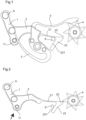
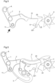
- THE figures 1 to 5 are schematic plan views of a corrector which corresponds to a particular embodiment of the actuation mechanism of the invention, the corrector being represented at four successive instants during its pivoting from its rest position ( figure 1 ) towards its tilted position.
- FIG. 6 is a schematic plan view of the corrector of figures 1 to 5 at a particular moment of its return to the rest position after having activated the rotating star.
- the schematic plan views of the figures 1 to 6 The appended documents illustrate an actuation mechanism for a timepiece according to one embodiment of the invention.
- the actuation mechanism shown in the figures is intended to equip a movement of a timepiece and is designed to be controlled by a user to correct an indication displayed by the timepiece.
- Such an actuating mechanism controllable from outside the timepiece is known as a “corrector” or “correction mechanism”.
- the actuation mechanisms according to the invention are not all correctors.
- the corrector shown in the figures 1 to 6 comprises a control member that can be operated manually from outside the timepiece (control member not shown, symbolized by an arrow in the figures 2 to 4 ) as well as a rocker 1 comprising an arm 2 and subjected to the action of a return spring 3 (visible only on the figures 1 And 6 ).
- the actuation mechanism further comprises a mobile to be actuated.
- it is a star 4 which has seven teeth.
- star 4 could for example carry an organ indicating the days of the week (not shown).
- the position of the star 4 is indexed by a jump spring 5 (visible only on the figures 1 And 6 ) which is recalled against the teeth of star 4.
- the rocker 1 of the corrector is pivotally mounted around an axis A and has a bulge 11 with which the control member is arranged to cooperate.
- the arm 2 of the rocker 1 is flexible and comprises an elastic part 21 and a rigid part which is constituted by a rigid shoe 22.
- the junction between the elastic part 21 and the shoe 22 forms an elbow preferably having an acute angle.
- the tip 23 of the elbow forms the active end of the rocker 1 and is arranged to push back a tooth of the star 4 when the rocker 1 pivots from its rest position (represented in the figure 1 ) towards its tilted position (pivots counterclockwise in the figures).
- the corrector further comprises a fixed stop 6 mounted on a fixed part of the movement of the timepiece comprising the corrector.
- This fixed stop can have any appropriate shape such as a stud, a pin or any element presenting a rigid and fixed bearing surface.
- the shoe 22 of the arm 2 of the rocker 1 has a leaning zone 221 which comes to rest against the fixed stop 6 when the tip 23 of the arm 2 pushes a tooth of the star 4 against the action of the jump spring 5. Indeed, in this situation, the tooth of the star 4 exerts a reaction force on the tip 23.
- the arm 2 of the rocker 1 and in particular the elastic part 21 are arranged so that said reaction force causes the flexion of the elastic part 21 of the arm 2. Within the limit of small deformations, the flexion of the elastic part 21 of the arm 2 results in a rotation of the end of the elastic part 21 as well as of the shoe 22 (in one direction corresponding to clockwise direction in the figures).
- Rocker 1 continues its rotation and arm 2 and its tip 23 now behave in a rigid manner which allows rocker 1 to drive star 4 in rotation.
- the rotation of the star 4 causes one of the teeth to lift the jump spring 5, which thus rises until the tip of its inclined plane has crossed the top of the tooth and passed onto the other side.
- the force that the inclined plane exerts on the top of the tooth no longer opposes the rotation of star 4, but on the contrary produces a torque which solicits star 4 in the direction in which it is already driven.
- the disappearance of the torque which until then opposed the rotation of the star 4 allows the elastic part 21 of the arm 2 of the rocker 1 to straighten out by moving the shoe 22 away from the fixed stop 6 ( figure 5 ).
- the rocker 1 of the corrector When, after having activated the corrector, the user releases the control member, the rocker 1 of the corrector is returned towards its rest position by the spring 3. However, the passage that the tip 23 must take to return to rest position is now crossed out by the tooth of star 4 which follows the one that the corrector has just pushed forward.
- the arm 2 of the corrector is capable of returning to the rest position, even in cases where the automatic increment mechanism of the star 4 blocks the rotation of the latter towards the rear. Indeed, it is possible to move the tip 23 and the shoe 22 away from the trajectory of the teeth of the star 4 by bending the elastic part 21 of the arm 2 in a second direction as shown in the Figure 6 .
- an actuation mechanism is produced, and in particular a correction mechanism which is efficient, reliable, compact, space-saving and simple to produce and which can be actuated at any time and successively, without waiting time between two actuations.
- the dimensioning of the flexible arm allows retraction without increasing the angular travel necessary for pivoting the mobile to be actuated.
- the rocker 1 drives the star 4 when it pivots from its rest position to its tilted position and does not drive the star 4 when it pivots from its tilted position to its tilted position. rest position.
- the mechanism could be arranged so that the rocker 1 drives the star 4 when it pivots from its tilted position to its rest position while it does not drive the star 4 when the rocker pivots. from its rest position to its tilted position.
- the actuation mechanism comprises a pivotally mounted rocker.
- the rocker comprises a flexible actuating arm comprising an active end arranged to cooperate with the teeth of a mobile to be actuated when the rocker pivots in a first direction.
- the actuation mechanism further comprises a fixed stop intended to be mounted on a fixed part of the timepiece.
- the actuating arm of the rocker comprises a rigid portion having a leaning zone arranged to cooperate with the fixed stop so that the leaning zone comes to rest on the fixed stop when the rocker pivots in the first direction and that the active end cooperates with the teeth of the mobile to be actuated.
- the actuation mechanism comprises a control member operable manually from outside the timepiece
- the rocker comprises a control element arranged to cooperate with the control member to rotate the rocker when the The control member is operated from outside the timepiece.
- the mobile to be actuated is subjected to the action of an elastic indexing force arranged to determine angular positions of said mobile, said elastic force being arranged to return the mobile in a indexed angular position when the mobile deviates from said indexed angular position.
- the actuating arm of the rocker has sufficient stiffness to allow it to push one of the teeth of the teeth of the mobile to be operated with sufficient force to overcome the torque maintaining the elastic indexing force when the leaning zone of the actuating arm is pressed against the fixed stop.
- the actuating arm comprises an elastic portion, having the shape of a leaf spring and a rigid heel, the heel forming an elbow with the elastic portion, the tip of said elbow forming the active end of the actuating arm .
- the flexible actuating arm is arranged to deform without driving the mobile to be actuated when the rocker pivots in a second direction opposite to the first and the active end comes into contact with a tooth of the mobile to be actuated.
- the actuating arm therefore has a stiffness chosen so that it can deform without overcoming the elastic indexing force of the mobile to be actuated when the rocker pivots in the second direction and the active end comes into contact with a tooth of the mobile to operate. It is possible, depending on the arrangement of the mechanism, that the mobile to be actuated does not remain completely immobile when the rocker pivots in the second direction and the active end comes into contact with a tooth of the mobile to be actuated. Said mobile can in fact shift or pivot slightly but never enough to change its indexed angular position or even to take an angular step which would result in the passage of the function controlled by the mobile to be actuated.
Landscapes
- Physics & Mathematics (AREA)
- General Physics & Mathematics (AREA)
- Orthopedics, Nursing, And Contraception (AREA)
- Electromechanical Clocks (AREA)
Priority Applications (1)
| Application Number | Priority Date | Filing Date | Title |
|---|---|---|---|
| EP22161897.8A EP4246247B1 (de) | 2022-03-14 | 2022-03-14 | Betätigungsmechanismus für uhr |
Applications Claiming Priority (1)
| Application Number | Priority Date | Filing Date | Title |
|---|---|---|---|
| EP22161897.8A EP4246247B1 (de) | 2022-03-14 | 2022-03-14 | Betätigungsmechanismus für uhr |
Publications (2)
| Publication Number | Publication Date |
|---|---|
| EP4246247A1 true EP4246247A1 (de) | 2023-09-20 |
| EP4246247B1 EP4246247B1 (de) | 2025-08-13 |
Family
ID=80739007
Family Applications (1)
| Application Number | Title | Priority Date | Filing Date |
|---|---|---|---|
| EP22161897.8A Active EP4246247B1 (de) | 2022-03-14 | 2022-03-14 | Betätigungsmechanismus für uhr |
Country Status (1)
| Country | Link |
|---|---|
| EP (1) | EP4246247B1 (de) |
Citations (4)
| Publication number | Priority date | Publication date | Assignee | Title |
|---|---|---|---|---|
| WO2012127054A1 (fr) * | 2011-03-23 | 2012-09-27 | Samep S.A. - Montres Emile Pequignet | Mecanisme d'entrainement instantane pour mouvement horloger |
| US20190025761A1 (en) * | 2017-07-18 | 2019-01-24 | Patek Philippe Sa Geneve | Indicator actuating organ for a timepiece |
| EP3489766A1 (de) | 2017-11-27 | 2019-05-29 | Montres Breguet S.A. | Mechanismus zur korrektur einer bewegungsfunktion einer uhr |
| EP3734372A1 (de) * | 2019-05-02 | 2020-11-04 | Patek Philippe SA Genève | Betätigungsvorrichtung eines zahnrads in einem uhrwerksmechanismus |
-
2022
- 2022-03-14 EP EP22161897.8A patent/EP4246247B1/de active Active
Patent Citations (4)
| Publication number | Priority date | Publication date | Assignee | Title |
|---|---|---|---|---|
| WO2012127054A1 (fr) * | 2011-03-23 | 2012-09-27 | Samep S.A. - Montres Emile Pequignet | Mecanisme d'entrainement instantane pour mouvement horloger |
| US20190025761A1 (en) * | 2017-07-18 | 2019-01-24 | Patek Philippe Sa Geneve | Indicator actuating organ for a timepiece |
| EP3489766A1 (de) | 2017-11-27 | 2019-05-29 | Montres Breguet S.A. | Mechanismus zur korrektur einer bewegungsfunktion einer uhr |
| EP3734372A1 (de) * | 2019-05-02 | 2020-11-04 | Patek Philippe SA Genève | Betätigungsvorrichtung eines zahnrads in einem uhrwerksmechanismus |
Also Published As
| Publication number | Publication date |
|---|---|
| EP4246247B1 (de) | 2025-08-13 |
Similar Documents
| Publication | Publication Date | Title |
|---|---|---|
| EP1335253B1 (de) | Jährlicher Kalendermechanismus für Uhrwerk | |
| EP2751623B1 (de) | Antriebsmechanismus eines anzeigers | |
| EP2503410B1 (de) | Kalendermechanismus, der einen Monatsschnellkorrektor umfasst | |
| EP1953611A1 (de) | Uhr, die einen Antriebsmechanismus einer Vorrichtung zur Anzeige einer mit der Zeit zusammenhängenden Größe umfasst | |
| EP2407833B1 (de) | Spielausgleichsmechanismus für Uhrwerk | |
| EP2180383B1 (de) | Hilfsvorrichtung zur Positionshaltung einer Datumsanzeigescheibe für Uhrwerk | |
| EP3483663B1 (de) | Antriebsvorrichtung für kalendersystem einer uhr | |
| EP3913442B1 (de) | Retrograder uhranzeigemechanismus, der mit einer sicherheitsvorrichtung ausgestattet ist | |
| EP3026504A1 (de) | Uhrmechanismus eines Jahres- oder ewigen Kalenders, und Uhr, die eine solche Anwendung umfasst | |
| CH712222A2 (fr) | Roue d'entraînement d'indicateur de date, mécanisme de calendrier, mouvement et pièce d'horlogerie. | |
| EP4246247B1 (de) | Betätigungsmechanismus für uhr | |
| EP1801671B1 (de) | Mit Arretierungsmitteln versehene Kalenderuhr | |
| CH713209B1 (fr) | Mécanisme d'affichage pour pièce d'horlogerie. | |
| EP4194965B1 (de) | Betätigungsmechanismus für uhr | |
| EP3026505A1 (de) | Uhrmechanismus eines Jahres- oder ewigen Kalenders, und Uhr, die eine solche Anwendung umfasst | |
| CH717217B1 (fr) | Mécanisme de réglage de balancier pour redémarrer le fonctionnement du balancier, mouvement et pièce d'horlogerie le comprenant. | |
| EP1586961A2 (de) | Uhr mit schnell umschaltendenden ewigen Kalender | |
| EP3882716B1 (de) | Uhr, die eine gezahnte scheibe umfasst, die durch eine raste indexiert ist | |
| EP3705950B1 (de) | Antriebsmechanismus für uhr | |
| EP4375763B1 (de) | Uhrwerk, das einen mechanismus zur korrektur einer anzeige umfasst | |
| EP1558971B1 (de) | Kalendarmechanismus für uhrwerk | |
| CH524847A (fr) | Montre-calendrier | |
| EP4617793B1 (de) | Kalendermechanismus für uhrwerk, der mindestens den retrograden kalender anzeigt | |
| EP4488769A1 (de) | Uhrmechanismus zur sukzessiven anzeige einer zeitinformationssequenz | |
| CH370015A (fr) | Mécanisme de remontoir et de mise à l'heure pour mouvement de montre |
Legal Events
| Date | Code | Title | Description |
|---|---|---|---|
| PUAI | Public reference made under article 153(3) epc to a published international application that has entered the european phase |
Free format text: ORIGINAL CODE: 0009012 |
|
| STAA | Information on the status of an ep patent application or granted ep patent |
Free format text: STATUS: THE APPLICATION HAS BEEN PUBLISHED |
|
| AK | Designated contracting states |
Kind code of ref document: A1 Designated state(s): AL AT BE BG CH CY CZ DE DK EE ES FI FR GB GR HR HU IE IS IT LI LT LU LV MC MK MT NL NO PL PT RO RS SE SI SK SM TR |
|
| STAA | Information on the status of an ep patent application or granted ep patent |
Free format text: STATUS: REQUEST FOR EXAMINATION WAS MADE |
|
| 17P | Request for examination filed |
Effective date: 20240312 |
|
| RBV | Designated contracting states (corrected) |
Designated state(s): AL AT BE BG CH CY CZ DE DK EE ES FI FR GB GR HR HU IE IS IT LI LT LU LV MC MK MT NL NO PL PT RO RS SE SI SK SM TR |
|
| P01 | Opt-out of the competence of the unified patent court (upc) registered |
Free format text: CASE NUMBER: APP_48691/2024 Effective date: 20240827 |
|
| GRAP | Despatch of communication of intention to grant a patent |
Free format text: ORIGINAL CODE: EPIDOSNIGR1 |
|
| STAA | Information on the status of an ep patent application or granted ep patent |
Free format text: STATUS: GRANT OF PATENT IS INTENDED |
|
| INTG | Intention to grant announced |
Effective date: 20250411 |
|
| GRAS | Grant fee paid |
Free format text: ORIGINAL CODE: EPIDOSNIGR3 |
|
| GRAA | (expected) grant |
Free format text: ORIGINAL CODE: 0009210 |
|
| STAA | Information on the status of an ep patent application or granted ep patent |
Free format text: STATUS: THE PATENT HAS BEEN GRANTED |
|
| AK | Designated contracting states |
Kind code of ref document: B1 Designated state(s): AL AT BE BG CH CY CZ DE DK EE ES FI FR GB GR HR HU IE IS IT LI LT LU LV MC MK MT NL NO PL PT RO RS SE SI SK SM TR |
|
| REG | Reference to a national code |
Ref country code: GB Ref legal event code: FG4D Free format text: NOT ENGLISH |
|
| REG | Reference to a national code |
Ref country code: CH Ref legal event code: EP |
|
| REG | Reference to a national code |
Ref country code: DE Ref legal event code: R096 Ref document number: 602022019225 Country of ref document: DE |
|
| REG | Reference to a national code |
Ref country code: IE Ref legal event code: FG4D Free format text: LANGUAGE OF EP DOCUMENT: FRENCH |
|
| REG | Reference to a national code |
Ref country code: CH Ref legal event code: R17 Free format text: ST27 STATUS EVENT CODE: U-0-0-R10-R17 (AS PROVIDED BY THE NATIONAL OFFICE) Effective date: 20251001 |
|
| REG | Reference to a national code |
Ref country code: NL Ref legal event code: MP Effective date: 20250813 |
|
| PG25 | Lapsed in a contracting state [announced via postgrant information from national office to epo] |
Ref country code: IS Free format text: LAPSE BECAUSE OF FAILURE TO SUBMIT A TRANSLATION OF THE DESCRIPTION OR TO PAY THE FEE WITHIN THE PRESCRIBED TIME-LIMIT Effective date: 20251213 |
|
| PG25 | Lapsed in a contracting state [announced via postgrant information from national office to epo] |
Ref country code: NO Free format text: LAPSE BECAUSE OF FAILURE TO SUBMIT A TRANSLATION OF THE DESCRIPTION OR TO PAY THE FEE WITHIN THE PRESCRIBED TIME-LIMIT Effective date: 20251113 |
|
| REG | Reference to a national code |
Ref country code: LT Ref legal event code: MG9D |
|
| PG25 | Lapsed in a contracting state [announced via postgrant information from national office to epo] |
Ref country code: PT Free format text: LAPSE BECAUSE OF FAILURE TO SUBMIT A TRANSLATION OF THE DESCRIPTION OR TO PAY THE FEE WITHIN THE PRESCRIBED TIME-LIMIT Effective date: 20251215 |
|
| PG25 | Lapsed in a contracting state [announced via postgrant information from national office to epo] |
Ref country code: FI Free format text: LAPSE BECAUSE OF FAILURE TO SUBMIT A TRANSLATION OF THE DESCRIPTION OR TO PAY THE FEE WITHIN THE PRESCRIBED TIME-LIMIT Effective date: 20250813 |
|
| PG25 | Lapsed in a contracting state [announced via postgrant information from national office to epo] |
Ref country code: HR Free format text: LAPSE BECAUSE OF FAILURE TO SUBMIT A TRANSLATION OF THE DESCRIPTION OR TO PAY THE FEE WITHIN THE PRESCRIBED TIME-LIMIT Effective date: 20250813 Ref country code: NL Free format text: LAPSE BECAUSE OF FAILURE TO SUBMIT A TRANSLATION OF THE DESCRIPTION OR TO PAY THE FEE WITHIN THE PRESCRIBED TIME-LIMIT Effective date: 20250813 |
|
| PG25 | Lapsed in a contracting state [announced via postgrant information from national office to epo] |
Ref country code: GR Free format text: LAPSE BECAUSE OF FAILURE TO SUBMIT A TRANSLATION OF THE DESCRIPTION OR TO PAY THE FEE WITHIN THE PRESCRIBED TIME-LIMIT Effective date: 20251114 |
|
| PG25 | Lapsed in a contracting state [announced via postgrant information from national office to epo] |
Ref country code: SE Free format text: LAPSE BECAUSE OF FAILURE TO SUBMIT A TRANSLATION OF THE DESCRIPTION OR TO PAY THE FEE WITHIN THE PRESCRIBED TIME-LIMIT Effective date: 20250813 |
|
| PG25 | Lapsed in a contracting state [announced via postgrant information from national office to epo] |
Ref country code: LV Free format text: LAPSE BECAUSE OF FAILURE TO SUBMIT A TRANSLATION OF THE DESCRIPTION OR TO PAY THE FEE WITHIN THE PRESCRIBED TIME-LIMIT Effective date: 20250813 |
|
| PG25 | Lapsed in a contracting state [announced via postgrant information from national office to epo] |
Ref country code: PL Free format text: LAPSE BECAUSE OF FAILURE TO SUBMIT A TRANSLATION OF THE DESCRIPTION OR TO PAY THE FEE WITHIN THE PRESCRIBED TIME-LIMIT Effective date: 20250813 Ref country code: BG Free format text: LAPSE BECAUSE OF FAILURE TO SUBMIT A TRANSLATION OF THE DESCRIPTION OR TO PAY THE FEE WITHIN THE PRESCRIBED TIME-LIMIT Effective date: 20250813 |
|
| PG25 | Lapsed in a contracting state [announced via postgrant information from national office to epo] |
Ref country code: RS Free format text: LAPSE BECAUSE OF FAILURE TO SUBMIT A TRANSLATION OF THE DESCRIPTION OR TO PAY THE FEE WITHIN THE PRESCRIBED TIME-LIMIT Effective date: 20251113 |
|
| PG25 | Lapsed in a contracting state [announced via postgrant information from national office to epo] |
Ref country code: ES Free format text: LAPSE BECAUSE OF FAILURE TO SUBMIT A TRANSLATION OF THE DESCRIPTION OR TO PAY THE FEE WITHIN THE PRESCRIBED TIME-LIMIT Effective date: 20250813 |
|
| REG | Reference to a national code |
Ref country code: AT Ref legal event code: MK05 Ref document number: 1825319 Country of ref document: AT Kind code of ref document: T Effective date: 20250813 |
|
| REG | Reference to a national code |
Ref country code: CH Ref legal event code: U11 Free format text: ST27 STATUS EVENT CODE: U-0-0-U10-U11 (AS PROVIDED BY THE NATIONAL OFFICE) Effective date: 20260401 |
|
| PG25 | Lapsed in a contracting state [announced via postgrant information from national office to epo] |
Ref country code: SM Free format text: LAPSE BECAUSE OF FAILURE TO SUBMIT A TRANSLATION OF THE DESCRIPTION OR TO PAY THE FEE WITHIN THE PRESCRIBED TIME-LIMIT Effective date: 20250813 |
|
| PG25 | Lapsed in a contracting state [announced via postgrant information from national office to epo] |
Ref country code: DK Free format text: LAPSE BECAUSE OF FAILURE TO SUBMIT A TRANSLATION OF THE DESCRIPTION OR TO PAY THE FEE WITHIN THE PRESCRIBED TIME-LIMIT Effective date: 20250813 |
|
| PG25 | Lapsed in a contracting state [announced via postgrant information from national office to epo] |
Ref country code: AT Free format text: LAPSE BECAUSE OF FAILURE TO SUBMIT A TRANSLATION OF THE DESCRIPTION OR TO PAY THE FEE WITHIN THE PRESCRIBED TIME-LIMIT Effective date: 20250813 |
|
| PG25 | Lapsed in a contracting state [announced via postgrant information from national office to epo] |
Ref country code: IT Free format text: LAPSE BECAUSE OF FAILURE TO SUBMIT A TRANSLATION OF THE DESCRIPTION OR TO PAY THE FEE WITHIN THE PRESCRIBED TIME-LIMIT Effective date: 20250813 |
|
| PG25 | Lapsed in a contracting state [announced via postgrant information from national office to epo] |
Ref country code: CZ Free format text: LAPSE BECAUSE OF FAILURE TO SUBMIT A TRANSLATION OF THE DESCRIPTION OR TO PAY THE FEE WITHIN THE PRESCRIBED TIME-LIMIT Effective date: 20250813 |
|
| PG25 | Lapsed in a contracting state [announced via postgrant information from national office to epo] |
Ref country code: SK Free format text: LAPSE BECAUSE OF FAILURE TO SUBMIT A TRANSLATION OF THE DESCRIPTION OR TO PAY THE FEE WITHIN THE PRESCRIBED TIME-LIMIT Effective date: 20250813 Ref country code: EE Free format text: LAPSE BECAUSE OF FAILURE TO SUBMIT A TRANSLATION OF THE DESCRIPTION OR TO PAY THE FEE WITHIN THE PRESCRIBED TIME-LIMIT Effective date: 20250813 |