EP4246535B1 - Conteneur pour le conditionnement, le stockage et l'élimination de déchets radioactifs - Google Patents
Conteneur pour le conditionnement, le stockage et l'élimination de déchets radioactifs Download PDFInfo
- Publication number
- EP4246535B1 EP4246535B1 EP23162304.2A EP23162304A EP4246535B1 EP 4246535 B1 EP4246535 B1 EP 4246535B1 EP 23162304 A EP23162304 A EP 23162304A EP 4246535 B1 EP4246535 B1 EP 4246535B1
- Authority
- EP
- European Patent Office
- Prior art keywords
- lid
- closing
- sealing
- thread
- seat
- Prior art date
- Legal status (The legal status is an assumption and is not a legal conclusion. Google has not performed a legal analysis and makes no representation as to the accuracy of the status listed.)
- Active
Links
Images




Classifications
-
- G—PHYSICS
- G21—NUCLEAR PHYSICS; NUCLEAR ENGINEERING
- G21F—PROTECTION AGAINST X-RADIATION, GAMMA RADIATION, CORPUSCULAR RADIATION OR PARTICLE BOMBARDMENT; TREATING RADIOACTIVELY CONTAMINATED MATERIAL; DECONTAMINATION ARRANGEMENTS THEREFOR
- G21F5/00—Transportable or portable shielded containers
- G21F5/06—Details of, or accessories to, the containers
- G21F5/12—Closures for containers; Sealing arrangements
-
- G—PHYSICS
- G21—NUCLEAR PHYSICS; NUCLEAR ENGINEERING
- G21F—PROTECTION AGAINST X-RADIATION, GAMMA RADIATION, CORPUSCULAR RADIATION OR PARTICLE BOMBARDMENT; TREATING RADIOACTIVELY CONTAMINATED MATERIAL; DECONTAMINATION ARRANGEMENTS THEREFOR
- G21F5/00—Transportable or portable shielded containers
- G21F5/06—Details of, or accessories to, the containers
- G21F5/12—Closures for containers; Sealing arrangements
- G21F5/125—Means to monitor or detect the leak-tightness of the closure
-
- Y—GENERAL TAGGING OF NEW TECHNOLOGICAL DEVELOPMENTS; GENERAL TAGGING OF CROSS-SECTIONAL TECHNOLOGIES SPANNING OVER SEVERAL SECTIONS OF THE IPC; TECHNICAL SUBJECTS COVERED BY FORMER USPC CROSS-REFERENCE ART COLLECTIONS [XRACs] AND DIGESTS
- Y02—TECHNOLOGIES OR APPLICATIONS FOR MITIGATION OR ADAPTATION AGAINST CLIMATE CHANGE
- Y02E—REDUCTION OF GREENHOUSE GAS [GHG] EMISSIONS, RELATED TO ENERGY GENERATION, TRANSMISSION OR DISTRIBUTION
- Y02E30/00—Energy generation of nuclear origin
- Y02E30/30—Nuclear fission reactors
Definitions
- the present invention relates to a cask for conditioning, storage and disposal of radioactive waste, in particular solid radioactive waste of medium activity.
- the present invention fits into the context of the cylindrical casks intended for conditioning, storage and disposal of solid radioactive waste of medium activity with reduced Alpha-emitting radionuclide (MA-Beta) content. It is understood that the cask of the invention is suitable for use in the conditioning, storage and disposal of other types of waste.
- MA-Beta Alpha-emitting radionuclide
- cylindrical casks made of suitable metal materials e.g. made by casting spheroidal cast iron or forging carbon steel, are particularly well known.
- the casks of this type consist of a main body provided with an access opening, and of a lid closing the opening of the body and fixed to the body by screws.
- a sealing system is placed between the body and the lid, which according to standards (such as the already mentioned Italian standard UNI 11784:2020) must consist of two gaskets in series.
- some known casks are provided with sealing systems with combined axial and radial gaskets, which besides being relatively complicated and costly to manufacture and install, may in some cases not be entirely satisfactory in use.
- the known casks have recesses, defined for example by the seats formed in the lid and into which the lid closing screws are recessed, and by the heads of the screws themselves, which are normally cylindrical with a hexagonal socket.
- the presence of recesses poses problems during the usual operations of decontamination of the cask, as washing liquid and contaminated particulate matter can stagnate there or enter into the gaps left between the seats of the bolted connections.
- the lid itself if it is in turn recessed between the sides of the main body of the cask, creates an additional closed recess, a potential source of water stagnations or contaminated particulate matter, especially in the case wherein, as is often the case, the cask is filled under a water head and subsequently drained, dried and decontaminated.
- a further aim of the invention is to improve the sealing function not only of the primary sealing system (operating between the lid and the body of the cask) but also of the secondary sealing systems (operating on openings formed in the lid and in the body of the cask for draining, venting and the internal pressure and leakage checks during operation).
- the present invention relates to a cask for conditioning, storage and disposal of radioactive waste, in particular solid radioactive waste of medium activity, as defined in essential terms in the appended claim 1 and, in its additional characters, in the dependent claims.
- the cask of the invention is fully effective in its functions, meeting in particular the requirements of the UNI 11784:2020 standard, while at the same time being particularly simple and inexpensive to make and use.
- the cask of the invention enables in particular a simplification of the assembly and commissioning operations, allowing, among other things, the required performance of the main sealing system to be maintained for each design condition, whether it is normal, abnormal or incidental.
- the primary sealing system (acting between lid and body of the cask) consists of two axial gaskets in series, which are coplanar and tightened in a coaxial direction to the (cylindrical) body of the cask, guaranteeing sealing performance under all design conditions; this results in a significant saving in manufacturing costs compared to other solutions and at the same time high sealing efficiency.
- the gaskets of the primary sealing system are protected against accidental events and therefore maintain their sealing efficiency even in the event of accidents (shocks and fires).
- the conical coupling surfaces are coupled to each other with a play less than the play existing between each lid closing screw and the respective through hole formed in the lid, thus ensuring the protection of the lid closing screws in the event of shocks.
- the gap between the radially outer portions of the flanges, on which the lid closing screws are placed, makes it possible to compensate, in the event of fire, for any differential thermal expansion and consequent tension and deformation states.
- the cask of the invention also has further features that allow to optimise the decontaminability of the outer surfaces of the cask, avoiding possible stagnations of liquids or solid particles.
- the lid closing screws are recessed in seats provided with radial outflow openings.
- the so-called secondary sealing systems acting on auxiliary openings formed on the body and on the lid of the cask, are also particularly simple and effective, as they consist of metal sealing rings, for example of C-Ring type, used together with threaded caps, in particular conical thread caps (NPT caps) treated with a solid lubricant and anti-seize paste that acts as a gas-tight sealing material.
- NPT caps conical thread caps
- the housing of an NPT cap is in fact definitely simpler and less costly than the construction of a seat for a second metal sealing ring, with the associated surface roughnesses, dimensional and geometric tolerances.
- commercially available NPT caps made of galvanised carbon steel can be used, which are definitely cheaper than custom-made sealing rings of C-Ring type made of high-grade Nickel alloys (e.g. Alloy 718) coated with Silver on the surface.
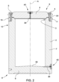
- the body 2 is in particular a cylindrical body having a cylindrical side wall 7 that extends along and about the axis A between a lower end 8, closed by a bottom wall 9, and an upper end 10, provided with the opening 3.
- Each hole 17 is connected to a drainage hole 18, formed radially through the side wall 7 at one bottom end of the respective hole 17 and communicating with the outside of the cask 1.
- the body 2 also comprises a lifting bead 19 that protrudes radially from the side wall 7 of the body 2 around the flange 11 and can be grasped by special lifting devices for manoeuvring the cask 1.
- the bead 19 has an upper outflow surface 20 inclined downwards (i.e. towards the lower end 8) with respect to the axis A and to the side wall 7.
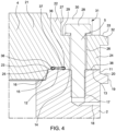
- the flange 22 comprises a sealing surface 23 cooperating with the sealing surface 12 of the body 2; and a radially outer portion 24 facing the portion 13 of the flange 11 of the body 2.
- the sealing surfaces 12, 23 are parallel to one another and perpendicular to the axis A.
- the central portion 21 has a conical coupling surface 25 adjacent to the sealing surface 23; the coupling surface 25 is defined by a side surface of the central portion 21 inclined towards the axis A and towards the lower end 8 and has a shape corresponding to the coupling surface 15 of the body 2.
- Portion 24 has a plurality of through holes 26 aligned to respective holes 17 of the body 2 to receive the closing screws 5.
- Each hole 26 comprises an enlarged upper portion 27 shaped to house a head 28 of the respective closing screw 5.
- the portion 27 has an annular bottom surface 29 from which a side wall 30 extends which surrounds the head 28 of the closing screw 5 but has a radial opening 31 facing toward a radially outer peripheral edge of the lid 4 and flush with the bottom surface 29.
- the lid 4 also comprises a lifting bead 32 that protrudes radially from the side wall 30 of the lid 4 around the flange 22 and can be grasped by special lifting devices.
- the bead 32 has an upper outflow surface 33 located flush with the bottom surface 29 and inclined downwards (i.e. towards the lower end 8) with respect to the axis A.
- the sealing system 6 comprises two gaskets 36 in series acting between the sealing surfaces 12, 23.
- gaskets 36 are axial gaskets acting parallel to the axis A between the sealing surfaces 12, 23, which are parallel to one another and perpendicular to the axis A.
- the gaskets 36 consist of respective metal sealing rings, for example metal O-rings or, preferably, energized metal C-Rings.
- the gaskets 36 are housed in respective grooves 37 formed on one of the sealing surfaces 12, 23 and protrude axially out of the grooves 37 to contact the opposite sealing surface 12, 23.
- the grooves 37 are formed on the sealing surface 23 of the lid 4 to prevent the gaskets 36 from being damaged when loading the waste into the cask 1.
- the gaskets 36 are fixed to the lid 4 and held in the respective grooves 37 by means of clips screwed into special recesses within the grooves 37.
- the closing screws 5 are hexagonal head screws, for example (but not necessarily) made of galvanised steel. This avoids the presence of a recessed hexagon, a potential site for stagnations and contaminated particulate matter, and screws supplied in a hot-dip galvanised state can be used, which are more resistant to general corrosion than electrolytic galvanisation. In this way, it is also possible to meet the regulatory requirements that envisage 50 years for a design life of the cask, which can be extended by a further 50 years in the event of scheduled maintenance intervention, e.g. for the replacement of components (gaskets, bolts, etc.) with incipient corrosion.
- the closing screws 5 are recessed, in use, in a respective hole 26 formed in the lid 4 so that they do not project axially out of hole 26.
- the head 28 of each closing screw 5 is housed in the portion 27 of the hole 26 and abuts, optionally with interposition of a washer, onto the bottom surface 29 of the portion 27.
- the closing screws 5 are tightened in use with a load higher than the minimum nominal load required to make contact between the flanges 11, 22, i.e. to obtain complete deformation of the gaskets 36 and bring the sealing surfaces 12, 23 in contact with each other (so-called metal-to-metal contact as indicated by the manufacturer).
- This margin on the tightening load has two indirect beneficial effects on the gaskets 36.
- the body 2 and the lid 4 are in contact by means of the respective conical coupling surfaces 15, 25 and the respective sealing surfaces 12, 23, which tighten the gaskets 36 together.
- the radially outer portions 13, 24 of the flanges 11, 22 remain axially spaced from each other by a gap 38 defined by the step 14.
- the gap 38 allow the preservation of the integrity of the closing screws 5 (and thus of the performance of the gaskets 36 they tighten) in the event of a fire, because it keeps the differential thermal expansions and the resulting tension and deformation states under control.
- the conical coupling surfaces 15, 25 are coupled to each other with a play less than the play existing between each closing screw 5 and the respective through hole 26 formed in the lid 4.
- the coupling surfaces 15, 25 of the body 2 and of the lid 4 fulfil the function of preventing the transverse sliding of the body 2 with respect to the lid 4, as well as the function of acting as a lead-in and centring while mounting the lid 4; in addition, the coupling surfaces 15, 25 increase the shielding of the cask 1 (with a zig-zag effect on radiations).
- the coupling surfaces 15, 25 instead are not supposed to have a sealing function: in fact, the gaskets 36 of the primary sealing system 6 both work axially and are not affected by any transverse shock.
- the cask 1 also comprises one or more auxiliary openings 39 formed passing-through in the body 2 and in the lid 4 for draining, venting and the internal pressure and leakage checks during operation; for example, auxiliary openings 39 are located in the middle of the lid 4 ( Figures 3 and 5 ) and in the side wall 7 of the body 2 at the lower end 8 ( Figure 6 ).
- Each auxiliary opening 39 is provided with a double-gasket closing and sealing device 40.
- Each device 40 comprises a blind flange 41 housed in a seat 42 aligned with the auxiliary opening 39; the blind flange 41 is fixed to the seat 42 by fixing screws 43 which engage respective threaded holes 44 formed on a bottom surface 45 of the seat 42 around the auxiliary opening 39.
- the device 40 also comprises a first auxiliary gasket 46 and a second auxiliary gasket 47 in series interposed between the blind flange 41 and the seat 42.
- the first auxiliary gasket 46 is defined by a metal sealing ring, for example an energized C-Ring, placed around the auxiliary opening 39 and interposed between a sealing surface 48 of the blind flange 41 and the bottom surface 45 of the seat 42, facing each other; for example, the auxiliary gasket 46 is housed in an annular groove 49 formed on the sealing surface 48 of the blind flange 41 and projecting from the groove 49.
- a metal sealing ring for example an energized C-Ring
- the second auxiliary gasket 47 is defined by a conical thread cap 50, specifically an NPT cap, which engages a corresponding conical threaded seat 51 formed in the auxiliary opening 39; the cap 50 has a thread 52 provided with a covering layer of solid lubricant and anti-seize paste which is interposed between the thread 52 of the cap 50 and the conical threaded seat 51 and acts as a gas-tight sealing material.
- the solid lubricant and anti-seize paste is in particular the same as the one used for the closing screws 5 and in general for all the threaded connections on the cask 1.
- a product normally used in a lubricant and anti-seize function on threaded parts is used for a sealing function.
- Molykote P-37 (Dow Corning) was used, which is a composition of mineral oils and solid lubricants, containing in particular zirconium oxide, mineral oils, graphite, calcium hydroxide, with an operating temperature of over 800°C. It is understood that other similar lubricant and anti-seize pastes can be used, even with different components.
- the blind flange 41 has an inspection opening 53 formed through the blind flange 41 and aligned with the auxiliary opening 39; the inspection opening 53 is closed by an inspection cap 54 which is also a conical thread cap (NPT cap) having a thread 55 provided with a covering layer of solid lubricant and anti-seize paste, screwed in a respective conical threaded seat 56 formed in the inspection opening 53; also in this case, the covering layer of solid lubricant and anti-seize paste is interposed between the thread 55 of the inspection cap 54 and the conical threaded seat 56 and acts as a gas-tight sealing material.
- NPT cap conical thread cap
- a shielding pin 57 (having essentially the function of radiation containment) is placed inside the auxiliary opening 39, further inwards the opening 39 of the inspection cap 54.
- control volume defined between the gaskets 36 of the primary sealing system 6 is also accessible for inspections through one or more inspection openings 53, formed through the flange 22 of the lid 4.
- inspection openings 53 formed through the flange 22 of the lid 4.
- Each inspection opening 53 extends through the lid 4 as far as the sealing surface 23 where it is placed between the two gaskets 36.
- Each inspection opening 53 is also closed by an inspection cap 54 which is also a conical thread cap (NPT cap) having a thread 55 provided with a covering layer of solid lubricant and anti-seize paste, screwed in a respective conical threaded seat 56 formed in the inspection opening 53; also in this case, the covering layer of solid lubricant and anti-seize paste is interposed between the thread 55 of the inspection cap 54 and the conical threaded seat 56 and acts as a gas-tight sealing material.
- NPT cap conical thread cap
- a shielding pin 57 having radiation containment function is placed inside the inspection opening 53, further inwards in the inspection opening 53 than the inspection cap 54.
- the fixing screws 43 of the blind flanges 41 are also hexagonal head screws, for example (but not necessarily) made of galvanised steel, and are recessed in the respective blind flange 41.
- the blind flanges 41 are normally mounted at least once drainage has been completed (and often after a drying phase), so the problem is less significant; in addition, the enlarged seat of the fixing screws 43 required to be able to access their hexagonal head with the socket spanner favours the decontamination of the surfaces enclosed therein.
- the double-gasket closing and sealing device 40 of one or more of the auxiliary openings 39 (for example, as shown in Figure 8 , the auxiliary opening 39 located on the body 2 at the lower end 8) is provided for connection to an external instrument, for example a manometer.
- the device 40 still comprises a blind flange 41, housed in a seat 42 aligned with the auxiliary opening 39, and a first auxiliary gasket 46 and a second auxiliary gasket 47 in series interposed between the blind flange 41 and the seat 42.
- the blind flange 41 is fixed to the housing 42 by fixing screws 43 that engage respective threaded holes formed on the bottom surface 45 of the seat 42 around the auxiliary opening 39.
- the first auxiliary gasket 46 is still defined by a metal sealing ring, for example an energized C-Ring, placed around the auxiliary opening 39 and interposed between the blind flange 41 and the bottom surface 45 of the seat 42; for example, the auxiliary gasket 46 is housed in an annular groove 49, formed on a sealing surface 48 of the blind flange 41 facing the bottom surface 45, and projects from the groove 49.
- a metal sealing ring for example an energized C-Ring
- the quick coupling seat 63 is provided with metal inner sealing elements (cooperating in use with the instrument being coupled to the joint 59). It is understood that joint 59 may be directly screwed in the conical threaded seat 51 with no need for the adapter nipple 60: in other words, the connection element 58 may consist of the joint 59 alone, or, like in the example shown, of an assembly formed by the joint 59 and by the nipple 60: in this case, the joint 59 is joined to the nipple 60, for example, by means of a conical threaded connection 64.
- the blind flange 41 has an inspection opening 53, formed through the blind flange 41 and aligned with the auxiliary opening 39 and closed by a conical thread inspection cap 54 (NPT cap) having a thread provided with a covering layer of solid lubricant and anti-seize paste, screwed in a respective conical threaded seat formed in the inspection opening 53 with also the function of gas-tight sealing material.
- NPT cap conical thread inspection cap 54
- the inspection cap 54 can take on different shapes and sizes: for example, while in the embodiment described above with reference to Figures 5-6 the inspection cap 54 is a hexagonal head cap, in the variant shown in Figures 8-9 the inspection cap 54 is a hexagonal recessed cap (i.e. having an inner hexagonal seat for being screwed/unscrewed).
- various surfaces of the cask 1 are inclined with respect to the axis A so as to favour the drainage of the cask 1 after loading under water head; for example, as described above, the outflow surface 16 adjacent to the coupling surfaces 15, 25, and the outflow surfaces 20, 33 of the beads 19, 32 are inclined.
- the bottom wall 9 of the body 2 has an outflow surface 65 inclined downwards and towards the side wall 7, so as to convey the liquids towards the auxiliary opening 39 placed at the bottom of the body 2.
- any gaps present on the cask 1 such as the gap 38 between the flanges 11, 22 and the volume determined by the play existing between the blind flanges 41 and the respective seats 42 on the body 2 and on the lid 4, can be filled with a sealing filler material (without structural functions), e.g. with neoprene strips, expanded graphite, etc.
- a sealing filler material without structural functions
- the sealing filler material it is not necessary for the sealing filler material to have special characteristics of resistance/integrity to ionising radiations.
Landscapes
- Physics & Mathematics (AREA)
- Engineering & Computer Science (AREA)
- General Engineering & Computer Science (AREA)
- High Energy & Nuclear Physics (AREA)
- Gasket Seals (AREA)
Claims (11)
- Château de transport (1) pour le conditionnement, le stockage et l'élimination des déchets radioactifs, en particulier des déchets radioactifs solides d'activité moyenne, comprenant : un corps principal creux (2) s'étendant le long et autour d'un axe longitudinal (A) et prévu avec une ouverture d'accès (3) ; un couvercle (4) fermant l'ouverture (3) et fixé au corps (2) par le biais de vis de fermeture (5) qui serrent l'une contre l'autre les brides (11, 22) respectives du corps (2) et du couvercle (4) et sont insérées dans des trous débouchants (17) respectifs formés dans le couvercle (4) et dans des trous borgnes filetés (26) respectifs formés dans le corps (2) ; et un système d'étanchéité primaire (6) agencé entre le corps (2) et le couvercle (4) et comprenant deux joints (36) en série ; dans lequel le corps (2) et le couvercle (4) sont prévus avec des surfaces de couplage coniques (15, 25) respectives adjacentes auxdites brides (11, 22) respectives et en contact entre elles et couplées entre elles avec un jeu inférieur au jeu existant entre chaque vis de fermeture (5) et le trou (17) respectif formé dans le couvercle (4) ; et en ce que lesdits joints (36) en série du système d'étanchéité primaire (6) sont des joints axiaux agissant parallèlement à l'axe (A) entre des surfaces d'étanchéité (12, 33) respectives, parallèles entre elles et perpendiculaires à l'axe (A) desdites brides (11, 22) du corps (2) et du couvercle (4) ; lesdites brides (11, 22) étant en contact entre elles au moyen desdites surfaces d'étanchéité (12, 23) respectives et comprenant des parties radialement externes (13, 24) respectives axialement espacées l'une de l'autre par un interstice (38), lesdites parties (13, 24) étant prévues avec lesdits trous débouchants (17) du couvercle (4) et lesdits trous borgnes filetés (26) du corps (2) qui reçoivent les vis de fermeture (5).
- Château de transport selon la revendication 1, dans lequel les vis de fermeture (5) sont serrées à l'usage avec une charge supérieure à la charge nominale minimum requise pour établir le contact entre les brides (11, 22), c'est-à-dire pour obtenir la déformation complète des joints (36) et amener les surfaces d'étanchéité (12, 23) en contact entre elles.
- Château de transport selon la revendication 1 ou 2, dans lequel chaque vis de fermeture (5) est encastrée, à l'usage, dans le trou (17) respectif formé dans le couvercle (4) et a une tête (28) qui est logée dans une partie supérieure agrandie (27) du trou (17) et vient en butée sur une surface inférieure (29) de ladite partie agrandie (27) ; ladite partie agrandie (27) étant prévue avec une ouverture radiale (31) orientée vers un bord périphérique radialement externe du couvercle (4) et à fleur avec la surface inférieure (29).
- Château de transport selon l'une des revendications précédentes, dans lequel les vis de fermeture (5) sont des vis à tête hexagonale.
- Château de transport selon l'une des revendications précédentes, ayant une ou plusieurs ouvertures auxiliaires (39) formées dans le couvercle (4) et/ou dans le corps (2) et prévues avec des dispositifs de fermeture et d'étanchéité à double joint (40) respectifs ; chaque dispositif de fermeture et d'étanchéité (40) comprenant une bride aveugle (41) fixée par le biais de vis de fixation (43) dans un siège (42) aligné avec l'ouverture auxiliaire (39) ; et un premier joint auxiliaire (46) et un deuxième joint auxiliaire (47) en série ; le premier joint auxiliaire (46) étant une bague d'étanchéité métallique, par exemple, une bague en C excitée ; et le deuxième joint auxiliaire (47) étant au moins un filetage (52) qui met en prise un siège fileté conique (51) formé dans l'ouverture auxiliaire (39) et est prévu avec une couche de recouvrement de pâte solide lubrifiante et antigrippage intercalée entre le filetage (52) et le siège fileté conique (51) respectif et sert également de matériau d'étanchéité étanche au gaz.
- Château de transport selon la revendication 5, dans lequel le dispositif de fermeture et d'étanchéité (40) comprend un capuchon à filetage conique (50) prévu avec ledit filetage (52) et vissé dans le siège fileté conique (51) pour fermer l'ouverture auxiliaire (39).
- Château de transport selon la revendication 5, dans lequel le dispositif de fermeture et d'étanchéité (40) comprend un élément de raccordement (58) ayant une première extrémité filetée (61) mettant en prise le siège fileté conique (51) au moyen dudit filetage (52) ; et une deuxième extrémité (62) prévue avec un siège à couplage rapide (63) formé pour recevoir un instrument externe, par exemple, un manomètre.
- Château de transport selon la revendication 7, dans lequel l'élément de raccordement (58) consiste en un joint à couplage rapide (59), vissé dans le siège fileté conique (51) au moyen du filetage (52) et prévu avec le siège à couplage rapide (63) ; ou en un ensemble formé par un joint à couplage rapide (59), prévu avec le siège à couplage rapide (63), et par un mamelon adaptateur (60) prévu avec le filetage (52) et vissé dans le siège fileté conique (51) et assemblé au joint à couplage rapide (59) par un couplage fileté (64).
- Château de transport selon l'une des revendications 5 à 8, dans lequel la bride aveugle (41) a une ouverture d'inspection (53) formée à travers la bride aveugle (41) et alignée avec l'ouverture auxiliaire (39) ; l'ouverture d'inspection (53) étant fermée par un capuchon d'inspection (54) qui est également un capuchon fileté conique vissé dans un siège fileté conique (56) respectif formé dans l'ouverture d'inspection (53) et ayant un filetage (55) prévu avec une couche de recouvrement de pâte solide lubrifiante et antigrippage intercalée entre le filetage (55) du capuchon d'inspection (54) et le siège fileté conique (56) respectif et sert également de matériau d'étanchéité étanche au gaz.
- Château de transport selon l'une des revendications 5 à 9, dans lequel ladite pâte solide lubrifiante et antigrippage est une composition d'huiles minérales et de lubrifiants solides.
- Château de transport selon l'une des revendications précédentes, dans lequel les joints (36) consistent en des bagues d'étanchéité métalliques respectives, par exemple une bague en C métallique excitée.
Applications Claiming Priority (1)
| Application Number | Priority Date | Filing Date | Title |
|---|---|---|---|
| IT202200005159 | 2022-03-16 |
Publications (2)
| Publication Number | Publication Date |
|---|---|
| EP4246535A1 EP4246535A1 (fr) | 2023-09-20 |
| EP4246535B1 true EP4246535B1 (fr) | 2025-06-25 |
Family
ID=81928091
Family Applications (1)
| Application Number | Title | Priority Date | Filing Date |
|---|---|---|---|
| EP23162304.2A Active EP4246535B1 (fr) | 2022-03-16 | 2023-03-16 | Conteneur pour le conditionnement, le stockage et l'élimination de déchets radioactifs |
Country Status (1)
| Country | Link |
|---|---|
| EP (1) | EP4246535B1 (fr) |
Families Citing this family (1)
| Publication number | Priority date | Publication date | Assignee | Title |
|---|---|---|---|---|
| FR3165351A1 (fr) * | 2024-08-05 | 2026-02-06 | Orano Nuclear Packages And Services | Emballage pour l’entreposage de matieres radioactives, presentant une conception amelioree pour le suivi de la temperature d’un joint d’etancheite associe au couvercle d’emballage |
Family Cites Families (3)
| Publication number | Priority date | Publication date | Assignee | Title |
|---|---|---|---|---|
| DE3010518A1 (de) * | 1980-03-19 | 1981-10-01 | GNS Gesellschaft für Nuklear-Service mbH, 4300 Essen | Bauelementensatz fuer den abgeschirmten transport und fuer die abgeschirmte lagerung von radioaktiven substanzen |
| DE3025795C2 (de) * | 1980-07-08 | 1986-08-28 | GNS Gesellschaft für Nuklear-Service mbH, 4300 Essen | Verfahren zur kontinuierlichen Überwachung von zwei Dichtungsbarrieren bei Abschirmtransport- und Lagerbehältern für radioaktive Substanzen |
| EP1047082A1 (fr) * | 1999-04-24 | 2000-10-25 | GNS GESELLSCHAFT FÜR NUKLEAR-SERVICE mbH | Conteneur de stockage pour matières radioactives |
-
2023
- 2023-03-16 EP EP23162304.2A patent/EP4246535B1/fr active Active
Also Published As
| Publication number | Publication date |
|---|---|
| EP4246535A1 (fr) | 2023-09-20 |
Similar Documents
| Publication | Publication Date | Title |
|---|---|---|
| US4460012A (en) | Cartridge-type valve | |
| US4465201A (en) | Conical O-ring seal | |
| RU2580992C2 (ru) | Уплотнение шарового поплавкового клапана с сильфоном и с-образным уплотнением | |
| EP0160576B1 (fr) | Clapet de non-retour à volet | |
| US5918911A (en) | Replacement and repair of nozzles for pressure vessels | |
| CA2446598C (fr) | Soupape de surete equipee de composants hautement resistants a la corrosion et rechangeables | |
| US4445042A (en) | Radiation-shielding transport and storage container | |
| EP4246535A1 (fr) | Conteneur pour le conditionnement, le stockage et l'élimination de déchets radioactifs | |
| US4542879A (en) | Valve ring arrangements in metallic valves, control valves, condensate removal devices, and other means for the prevention of leakages due to corrosion | |
| US10385983B2 (en) | Burst disk assembly for high and ultra high vacuum containment vessels | |
| US5272732A (en) | Reactor cavity seal joint | |
| JP2007100959A (ja) | フランジ付連結装置 | |
| EP0143258B1 (fr) | Siège arrière pour tige de soupape disposé dans le couvercle protecteur de logement | |
| US4540013A (en) | Fire responsive stem retention apparatus | |
| JP2002174694A (ja) | 輸送貯蔵用密閉容器 | |
| JPS60222669A (ja) | 弁及び弁座保持器の固定方法 | |
| US3187929A (en) | Unitary quick-opening closure device | |
| JP2005024514A (ja) | 放射性物質の輸送貯蔵キャスク | |
| US3272224A (en) | Hooded gas distribution valve for underground use | |
| US3162453A (en) | Combined valve stuffing box and bonnet mounting | |
| CN215445465U (zh) | 一种工业气体管道阀门连接结构 | |
| CN105759388A (zh) | 高压容器窥视装置 | |
| CN113374957B (zh) | 衬里法兰盖及管口连接结构 | |
| CA2261306A1 (fr) | Ressort a disques hermetiquement clos pour boite a garniture a charge dynamique | |
| WO2009029878A1 (fr) | Dispositif d'étanchéité possédant un diamètre intérieur formant joint |
Legal Events
| Date | Code | Title | Description |
|---|---|---|---|
| PUAI | Public reference made under article 153(3) epc to a published international application that has entered the european phase |
Free format text: ORIGINAL CODE: 0009012 |
|
| STAA | Information on the status of an ep patent application or granted ep patent |
Free format text: STATUS: THE APPLICATION HAS BEEN PUBLISHED |
|
| AK | Designated contracting states |
Kind code of ref document: A1 Designated state(s): AL AT BE BG CH CY CZ DE DK EE ES FI FR GB GR HR HU IE IS IT LI LT LU LV MC ME MK MT NL NO PL PT RO RS SE SI SK SM TR |
|
| STAA | Information on the status of an ep patent application or granted ep patent |
Free format text: STATUS: REQUEST FOR EXAMINATION WAS MADE |
|
| 17P | Request for examination filed |
Effective date: 20240314 |
|
| RBV | Designated contracting states (corrected) |
Designated state(s): AL AT BE BG CH CY CZ DE DK EE ES FI FR GB GR HR HU IE IS IT LI LT LU LV MC ME MK MT NL NO PL PT RO RS SE SI SK SM TR |
|
| P01 | Opt-out of the competence of the unified patent court (upc) registered |
Effective date: 20240506 |
|
| GRAP | Despatch of communication of intention to grant a patent |
Free format text: ORIGINAL CODE: EPIDOSNIGR1 |
|
| STAA | Information on the status of an ep patent application or granted ep patent |
Free format text: STATUS: GRANT OF PATENT IS INTENDED |
|
| INTG | Intention to grant announced |
Effective date: 20250129 |
|
| GRAS | Grant fee paid |
Free format text: ORIGINAL CODE: EPIDOSNIGR3 |
|
| GRAA | (expected) grant |
Free format text: ORIGINAL CODE: 0009210 |
|
| STAA | Information on the status of an ep patent application or granted ep patent |
Free format text: STATUS: THE PATENT HAS BEEN GRANTED |
|
| AK | Designated contracting states |
Kind code of ref document: B1 Designated state(s): AL AT BE BG CH CY CZ DE DK EE ES FI FR GB GR HR HU IE IS IT LI LT LU LV MC ME MK MT NL NO PL PT RO RS SE SI SK SM TR |
|
| REG | Reference to a national code |
Ref country code: GB Ref legal event code: FG4D |
|
| REG | Reference to a national code |
Ref country code: CH Ref legal event code: EP |
|
| REG | Reference to a national code |
Ref country code: CH Ref legal event code: EP |
|
| REG | Reference to a national code |
Ref country code: IE Ref legal event code: FG4D |
|
| REG | Reference to a national code |
Ref country code: DE Ref legal event code: R096 Ref document number: 602023004187 Country of ref document: DE |
|
| PG25 | Lapsed in a contracting state [announced via postgrant information from national office to epo] |
Ref country code: FI Free format text: LAPSE BECAUSE OF FAILURE TO SUBMIT A TRANSLATION OF THE DESCRIPTION OR TO PAY THE FEE WITHIN THE PRESCRIBED TIME-LIMIT Effective date: 20250625 |
|
| REG | Reference to a national code |
Ref country code: LT Ref legal event code: MG9D |
|
| PG25 | Lapsed in a contracting state [announced via postgrant information from national office to epo] |
Ref country code: NO Free format text: LAPSE BECAUSE OF FAILURE TO SUBMIT A TRANSLATION OF THE DESCRIPTION OR TO PAY THE FEE WITHIN THE PRESCRIBED TIME-LIMIT Effective date: 20250925 Ref country code: GR Free format text: LAPSE BECAUSE OF FAILURE TO SUBMIT A TRANSLATION OF THE DESCRIPTION OR TO PAY THE FEE WITHIN THE PRESCRIBED TIME-LIMIT Effective date: 20250926 |
|
| REG | Reference to a national code |
Ref country code: SK Ref legal event code: T3 Ref document number: E 46860 Country of ref document: SK |
|
| PG25 | Lapsed in a contracting state [announced via postgrant information from national office to epo] |
Ref country code: BG Free format text: LAPSE BECAUSE OF FAILURE TO SUBMIT A TRANSLATION OF THE DESCRIPTION OR TO PAY THE FEE WITHIN THE PRESCRIBED TIME-LIMIT Effective date: 20250625 |
|
| PG25 | Lapsed in a contracting state [announced via postgrant information from national office to epo] |
Ref country code: HR Free format text: LAPSE BECAUSE OF FAILURE TO SUBMIT A TRANSLATION OF THE DESCRIPTION OR TO PAY THE FEE WITHIN THE PRESCRIBED TIME-LIMIT Effective date: 20250625 |
|
| PG25 | Lapsed in a contracting state [announced via postgrant information from national office to epo] |
Ref country code: RS Free format text: LAPSE BECAUSE OF FAILURE TO SUBMIT A TRANSLATION OF THE DESCRIPTION OR TO PAY THE FEE WITHIN THE PRESCRIBED TIME-LIMIT Effective date: 20250925 |
|
| PG25 | Lapsed in a contracting state [announced via postgrant information from national office to epo] |
Ref country code: LV Free format text: LAPSE BECAUSE OF FAILURE TO SUBMIT A TRANSLATION OF THE DESCRIPTION OR TO PAY THE FEE WITHIN THE PRESCRIBED TIME-LIMIT Effective date: 20250625 |
|
| REG | Reference to a national code |
Ref country code: NL Ref legal event code: MP Effective date: 20250625 |
|
| PG25 | Lapsed in a contracting state [announced via postgrant information from national office to epo] |
Ref country code: NL Free format text: LAPSE BECAUSE OF FAILURE TO SUBMIT A TRANSLATION OF THE DESCRIPTION OR TO PAY THE FEE WITHIN THE PRESCRIBED TIME-LIMIT Effective date: 20250625 |
|
| PG25 | Lapsed in a contracting state [announced via postgrant information from national office to epo] |
Ref country code: PT Free format text: LAPSE BECAUSE OF FAILURE TO SUBMIT A TRANSLATION OF THE DESCRIPTION OR TO PAY THE FEE WITHIN THE PRESCRIBED TIME-LIMIT Effective date: 20251027 |
|
| REG | Reference to a national code |
Ref country code: AT Ref legal event code: MK05 Ref document number: 1807455 Country of ref document: AT Kind code of ref document: T Effective date: 20250625 |
|
| PG25 | Lapsed in a contracting state [announced via postgrant information from national office to epo] |
Ref country code: IS Free format text: LAPSE BECAUSE OF FAILURE TO SUBMIT A TRANSLATION OF THE DESCRIPTION OR TO PAY THE FEE WITHIN THE PRESCRIBED TIME-LIMIT Effective date: 20251025 |
|
| PG25 | Lapsed in a contracting state [announced via postgrant information from national office to epo] |
Ref country code: AT Free format text: LAPSE BECAUSE OF FAILURE TO SUBMIT A TRANSLATION OF THE DESCRIPTION OR TO PAY THE FEE WITHIN THE PRESCRIBED TIME-LIMIT Effective date: 20250625 Ref country code: SM Free format text: LAPSE BECAUSE OF FAILURE TO SUBMIT A TRANSLATION OF THE DESCRIPTION OR TO PAY THE FEE WITHIN THE PRESCRIBED TIME-LIMIT Effective date: 20250625 |
|
| PG25 | Lapsed in a contracting state [announced via postgrant information from national office to epo] |
Ref country code: CZ Free format text: LAPSE BECAUSE OF FAILURE TO SUBMIT A TRANSLATION OF THE DESCRIPTION OR TO PAY THE FEE WITHIN THE PRESCRIBED TIME-LIMIT Effective date: 20250625 |
|
| PG25 | Lapsed in a contracting state [announced via postgrant information from national office to epo] |
Ref country code: PL Free format text: LAPSE BECAUSE OF FAILURE TO SUBMIT A TRANSLATION OF THE DESCRIPTION OR TO PAY THE FEE WITHIN THE PRESCRIBED TIME-LIMIT Effective date: 20250625 |
|
| PG25 | Lapsed in a contracting state [announced via postgrant information from national office to epo] |
Ref country code: EE Free format text: LAPSE BECAUSE OF FAILURE TO SUBMIT A TRANSLATION OF THE DESCRIPTION OR TO PAY THE FEE WITHIN THE PRESCRIBED TIME-LIMIT Effective date: 20250625 |
|
| PG25 | Lapsed in a contracting state [announced via postgrant information from national office to epo] |
Ref country code: ES Free format text: LAPSE BECAUSE OF FAILURE TO SUBMIT A TRANSLATION OF THE DESCRIPTION OR TO PAY THE FEE WITHIN THE PRESCRIBED TIME-LIMIT Effective date: 20250625 |
|
| REG | Reference to a national code |
Ref country code: CH Ref legal event code: U11 Free format text: ST27 STATUS EVENT CODE: U-0-0-U10-U11 (AS PROVIDED BY THE NATIONAL OFFICE) Effective date: 20260401 |
|
| PG25 | Lapsed in a contracting state [announced via postgrant information from national office to epo] |
Ref country code: DK Free format text: LAPSE BECAUSE OF FAILURE TO SUBMIT A TRANSLATION OF THE DESCRIPTION OR TO PAY THE FEE WITHIN THE PRESCRIBED TIME-LIMIT Effective date: 20250625 |
|
| PG25 | Lapsed in a contracting state [announced via postgrant information from national office to epo] |
Ref country code: IT Free format text: LAPSE BECAUSE OF FAILURE TO SUBMIT A TRANSLATION OF THE DESCRIPTION OR TO PAY THE FEE WITHIN THE PRESCRIBED TIME-LIMIT Effective date: 20250625 |
|
| PGFP | Annual fee paid to national office [announced via postgrant information from national office to epo] |
Ref country code: RO Payment date: 20260304 Year of fee payment: 4 Ref country code: BE Payment date: 20260323 Year of fee payment: 4 |
|
| PGFP | Annual fee paid to national office [announced via postgrant information from national office to epo] |
Ref country code: SK Payment date: 20260223 Year of fee payment: 4 |
|
| PLBE | No opposition filed within time limit |
Free format text: ORIGINAL CODE: 0009261 |
|
| STAA | Information on the status of an ep patent application or granted ep patent |
Free format text: STATUS: NO OPPOSITION FILED WITHIN TIME LIMIT |
|
| REG | Reference to a national code |
Ref country code: CH Ref legal event code: L10 Free format text: ST27 STATUS EVENT CODE: U-0-0-L10-L00 (AS PROVIDED BY THE NATIONAL OFFICE) Effective date: 20260507 |