EP4246785A1 - Messverfahren einer rotoranordnung für eine windkrafanlage - Google Patents
Messverfahren einer rotoranordnung für eine windkrafanlage Download PDFInfo
- Publication number
- EP4246785A1 EP4246785A1 EP22162426.5A EP22162426A EP4246785A1 EP 4246785 A1 EP4246785 A1 EP 4246785A1 EP 22162426 A EP22162426 A EP 22162426A EP 4246785 A1 EP4246785 A1 EP 4246785A1
- Authority
- EP
- European Patent Office
- Prior art keywords
- rotor
- points
- house
- bearing
- axis
- Prior art date
- Legal status (The legal status is an assumption and is not a legal conclusion. Google has not performed a legal analysis and makes no representation as to the accuracy of the status listed.)
- Withdrawn
Links
- 238000000034 method Methods 0.000 title claims abstract description 26
- 238000005259 measurement Methods 0.000 claims description 30
- 238000001514 detection method Methods 0.000 claims description 3
- 230000008878 coupling Effects 0.000 description 4
- 238000010168 coupling process Methods 0.000 description 4
- 238000005859 coupling reaction Methods 0.000 description 4
- 238000000691 measurement method Methods 0.000 description 3
- 230000001419 dependent effect Effects 0.000 description 1
Images


Classifications
-
- H—ELECTRICITY
- H02—GENERATION; CONVERSION OR DISTRIBUTION OF ELECTRIC POWER
- H02K—DYNAMO-ELECTRIC MACHINES
- H02K15/00—Processes or apparatus specially adapted for manufacturing, assembling, maintaining or repairing of dynamo-electric machines
- H02K15/50—Disassembling, repairing or modifying dynamo-electric machines
-
- H—ELECTRICITY
- H02—GENERATION; CONVERSION OR DISTRIBUTION OF ELECTRIC POWER
- H02K—DYNAMO-ELECTRIC MACHINES
- H02K15/00—Processes or apparatus specially adapted for manufacturing, assembling, maintaining or repairing of dynamo-electric machines
- H02K15/16—Centring rotors within the stators
-
- H—ELECTRICITY
- H02—GENERATION; CONVERSION OR DISTRIBUTION OF ELECTRIC POWER
- H02K—DYNAMO-ELECTRIC MACHINES
- H02K15/00—Processes or apparatus specially adapted for manufacturing, assembling, maintaining or repairing of dynamo-electric machines
- H02K15/02—Processes or apparatus specially adapted for manufacturing, assembling, maintaining or repairing of dynamo-electric machines of stator or rotor bodies
- H02K15/03—Processes or apparatus specially adapted for manufacturing, assembling, maintaining or repairing of dynamo-electric machines of stator or rotor bodies having permanent magnets
-
- H—ELECTRICITY
- H02—GENERATION; CONVERSION OR DISTRIBUTION OF ELECTRIC POWER
- H02K—DYNAMO-ELECTRIC MACHINES
- H02K15/00—Processes or apparatus specially adapted for manufacturing, assembling, maintaining or repairing of dynamo-electric machines
- H02K15/90—Positioning or clamping dynamo-electric machines, e.g. jigs
-
- H—ELECTRICITY
- H02—GENERATION; CONVERSION OR DISTRIBUTION OF ELECTRIC POWER
- H02K—DYNAMO-ELECTRIC MACHINES
- H02K5/00—Casings; Enclosures; Supports
- H02K5/04—Casings or enclosures characterised by the shape, form or construction thereof
- H02K5/16—Means for supporting bearings, e.g. insulating supports or means for fitting bearings in the bearing-shields
- H02K5/173—Means for supporting bearings, e.g. insulating supports or means for fitting bearings in the bearing-shields using bearings with rolling contact, e.g. ball bearings
- H02K5/1737—Means for supporting bearings, e.g. insulating supports or means for fitting bearings in the bearing-shields using bearings with rolling contact, e.g. ball bearings radially supporting the rotor around a fixed spindle; radially supporting the rotor directly
-
- H—ELECTRICITY
- H02—GENERATION; CONVERSION OR DISTRIBUTION OF ELECTRIC POWER
- H02K—DYNAMO-ELECTRIC MACHINES
- H02K7/00—Arrangements for handling mechanical energy structurally associated with dynamo-electric machines, e.g. structural association with mechanical driving motors or auxiliary dynamo-electric machines
- H02K7/08—Structural association with bearings
- H02K7/086—Structural association with bearings radially supporting the rotor around a fixed spindle; radially supporting the rotor directly
-
- H—ELECTRICITY
- H02—GENERATION; CONVERSION OR DISTRIBUTION OF ELECTRIC POWER
- H02K—DYNAMO-ELECTRIC MACHINES
- H02K1/00—Details of the magnetic circuit
- H02K1/06—Details of the magnetic circuit characterised by the shape, form or construction
- H02K1/22—Rotating parts of the magnetic circuit
- H02K1/27—Rotor cores with permanent magnets
- H02K1/2786—Outer rotors
- H02K1/2787—Outer rotors the magnetisation axis of the magnets being perpendicular to the rotor axis
- H02K1/2789—Outer rotors the magnetisation axis of the magnets being perpendicular to the rotor axis the rotor consisting of two or more circumferentially positioned magnets
- H02K1/2791—Surface mounted magnets; Inset magnets
-
- H—ELECTRICITY
- H02—GENERATION; CONVERSION OR DISTRIBUTION OF ELECTRIC POWER
- H02K—DYNAMO-ELECTRIC MACHINES
- H02K2213/00—Specific aspects, not otherwise provided for and not covered by codes H02K2201/00 - H02K2211/00
- H02K2213/09—Machines characterised by the presence of elements which are subject to variation, e.g. adjustable bearings, reconfigurable windings, variable pitch ventilators
-
- H—ELECTRICITY
- H02—GENERATION; CONVERSION OR DISTRIBUTION OF ELECTRIC POWER
- H02K—DYNAMO-ELECTRIC MACHINES
- H02K7/00—Arrangements for handling mechanical energy structurally associated with dynamo-electric machines, e.g. structural association with mechanical driving motors or auxiliary dynamo-electric machines
- H02K7/18—Structural association of electric generators with mechanical driving motors, e.g. with turbines
- H02K7/1807—Rotary generators
- H02K7/1823—Rotary generators structurally associated with turbines or similar engines
- H02K7/183—Rotary generators structurally associated with turbines or similar engines wherein the turbine is a wind turbine
- H02K7/1838—Generators mounted in a nacelle or similar structure of a horizontal axis wind turbine
-
- Y—GENERAL TAGGING OF NEW TECHNOLOGICAL DEVELOPMENTS; GENERAL TAGGING OF CROSS-SECTIONAL TECHNOLOGIES SPANNING OVER SEVERAL SECTIONS OF THE IPC; TECHNICAL SUBJECTS COVERED BY FORMER USPC CROSS-REFERENCE ART COLLECTIONS [XRACs] AND DIGESTS
- Y02—TECHNOLOGIES OR APPLICATIONS FOR MITIGATION OR ADAPTATION AGAINST CLIMATE CHANGE
- Y02E—REDUCTION OF GREENHOUSE GAS [GHG] EMISSIONS, RELATED TO ENERGY GENERATION, TRANSMISSION OR DISTRIBUTION
- Y02E10/00—Energy generation through renewable energy sources
- Y02E10/70—Wind energy
- Y02E10/72—Wind turbines with rotation axis in wind direction
Definitions
- the invention relates to a method and an arrangement for measuring the position of a plurality of points in a rotor of an electrical generator.
- the invention further relates to a method for assembling a rotor for an electrical generator.
- the invention can be applied to an electrical generator for a wind turbine. More particularly, but not exclusively, the invention can be applied to a permanent magnet electrical generator.
- the airgap which is formed between the stator and a rotor in a wind turbine electrical generator is an important design feature that contributes to the overall efficiency of the wind turbine.
- Fluctuations of the airgap are in particular influenced by the eccentricity of the coupling between the stator and the rotor of the electrical generator.
- the overall eccentricity is determined by the shape of the rotor house and of the bearing assembly, by the different radial extensions of the magnets and by the misalignment between the axes of the rotor and the stator.
- a method for measuring the position of a plurality of points in a rotor of an electrical machine including a rotor house, a rotor bearing and a brake disc, the method including the steps of:
- the method may partly be implemented in software and/or hardware.
- the electrical machine may be an electrical generator or an electrical motor.
- the electrical machine may be an electrical generator of a wind turbine.
- Measuring a plurality of points in a rotor of an electrical machine helps in defining the shape of the rotor or the eccentricity of the rotor one the rotor is coupled to the stator of the electrical machine. This may be used for conveniently coupling a plurality of magnets in the plurality of seats, so that the thickness of the air gap between the rotor and the stator is kept constant and as close as possible to a minimum desired value.
- an assembly method for assembling a rotor of an electrical machine includes the steps of:
- the assembly method according to the present invention minimizes the eccentricity of the rotor when coupled to the stator.
- the variability parameter may be any of:
- At least a portion of the plurality of points to be measured are defined on the rotor bearing. At least another portion of the plurality of points to be measured are defined on an inside of the rotor house.
- Two pluralities of points may be measured, the two pluralities of points being respectively defined on respective planes at two respective axial ends of the rotor house or respectively close thereto.
- a third plurality of points may be measured, the third plurality of points being axially intermediate between the two axial ends of the rotor house.
- a measurement arrangement for measuring the position of a plurality of points in a rotor of an electrical machine including a rotor house and a rotor bearing, the arrangement including:
- the measurement device is an optic device, particularly it may be laser device.
- the measurement device may be a light detection and ranging device.
- FIG. 1 shows a wind turbine 1 according to the invention.
- the wind turbine 1 comprises a tower 2, which is mounted on a non-depicted foundation.
- a nacelle 3 is arranged on top of the tower 2.
- the nacelle 3 comprises a main frame 7 rotatably coupled with the tower 2, an electrical generator 10 rotatably coupled with the main frame 7 and an hub 9 fixed to a rotor 30 of the electrical generator 10.
- the wind turbine 1 further comprises a wind rotor 5 including the hub 9 and at least one blade 4 fixed to the hub 9 (in the embodiment of Figure 1 , the wind rotor comprises three blades 4.
- the wind rotor 5 is rotatable around a rotational longitudinal axis Y.
- the blades 4 extend substantially radially with respect to the longitudinal rotational axis Y.
- the electrical generator 10 including the rotor 30 and a stator (not visible in figure 1 ) fixed to the main frame 7 of the nacelle 3.
- the rotor 30 is radially external to the stator.
- the rotor 30 is rotatable with respect to the stator about the longitudinal rotational axis Y.
- FIG. 2 shows a schematic view of a cross section of the electrical generator 10 on a radial plane orthogonal to the longitudinal rotational axis Y.
- the electrical generator 10 including the rotor 30 and the stator 20, which is radially internal to the rotor 30.
- the rotor 30 and the stator 20 are ideally represents as two coaxial ideal cylinders.
- the electrical generator 10 comprises an airgap 15 radially interposed between the stator 20 and the rotor 30, the airgap 15 extending circumferentially about the rotational axis Y.
- the stator 20 comprises a cylindrical inner core 21 to which six segments 45 are attached. Each segment 45 has a circumferential angular extension of 60°.
- the stator 20 comprises a plurality of segments having another number (different from six) of segments.
- the rotor 30 comprises a plurality of circumferentially distributed permanent magnets 36 facing the airgap 15.
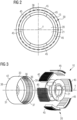
- FIG. 3 shows an exploded view of the electrical generator 10 showing axonometric schematic representation of the rotor 30 and the stator 20.
- the rotor 30 comprises a cylindrical rotor house 31 axially extending between a drive end 37, which is subject to be mounted adjacent to the hub of the wind rotor 5, and an axially opposite non-drive end 38, which is subject to be mounted adjacent to the main frame 7 of the nacelle 3.
- the rotor house has cylindrical hollow shape radially extending between an inner surface 39, on which a plurality of respective seats for the permanent magnets 36 are defined, and an external surface 42.
- the magnets 31 are distributed on the inner side 39 of the rotor house 31 according to axial columns. Each column of magnets comprises a plurality of magnets 36 (for example two magnets 36 as shown in figure 2 ) aligned along the rotational axis Y.
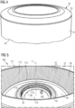
- Figure 4 shows an assembly 35 including components of the rotor 30.
- the assembly 35 includes the rotor house 31, a brake disc 33 and a rotor bearing 32 (not visible in the view of figure 4 , where the external surface 42 of the rotor house 31 is shown).
- the brake disc 33 is provided at the non-drive end 38 and radially extends from the rotor house 31 towards the axis of the rotor house 31.
- the assembly 35 may not include a brake disc 33.
- Figure 5 shows an inside of the assembly 35, where the rotor bearing 32 and the inner surface 39 of the rotor house 31 are visible.
- the rotor bearing 32 is provided at the non-drive end 38 and in operation is coupled with the stator 20, thus permitting the rotation of the rotor 30 with respect to the longitudinal axis Y of the generator 10.
- the rotor bearing 32 defines an axis of rotation which is in operation to be ideally aligned to the longitudinal axis Y.
- the rotor bearing 32 axially extend between the brake disc 33 and an inner rotor plate 34.
- the inner rotor plate 34 extends radially between the rotor bearing 32 and the inner surface 39, the inner rotor plate 34 being fixed to an inner front surface 46 of the rotor bearing 32.
- Figure 5 further shows a measurement arrangement 100 for measuring the position of a plurality of points 111, 112, 113, 114, 115 in the assembly 35.
- the measurement arrangement 100 includes a supporting structure, for example a 101 for receiving and supporting the assembly 35.
- the measurement arrangement 100 includes a measurement device 140 movable with respect to the supporting structure 101 for measuring a plurality of distances between the axis Z and the plurality of points 111, 112, 113, 114, 115 to be measured. At least a portion of the plurality of points 111, 112, 113, 114, 115 to be measured may be defined on an inside of the rotor house 31, i.e.
- a first plurality of points 111 may be defined at the drive end 37. Each of the first plurality of points 111 may be for example defined along a respective seat 41 for the permanent magnets 36.
- a second plurality of points 112 may be defined at the opposite axial ends of the seat 41, i.e. the axial ends of the seat 41 that are closer to the non-drive end 38.
- a third plurality of points 113 may be defined along the seat 41 for the permanent magnets 36 at intermediate positions between the first plurality of points 111 and the second plurality of points 112. The third plurality of points 113 may lie on a same plane orthogonal the axis Z.
- a fourth plurality of points 114 may be defined on the rotor bearing 32, for example along the border of the rotor bearing 32 which is closer to the drive end 37.
- the fourth plurality of points 114 may be defined also on the inner front surface 46 of the rotor bearing 32. Reflectors may be positioned on the inner front surface 46 to facilitate the measurements by the measurement device 140.
- a fifth plurality of points 115 along the border of the rotor bearing 32 which is closer to the non-drive end 38.
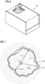
- Figure 6 shows a magnified view of the measurement device 140.
- the measurement device 140 may be an optic device, in particular a laser device.
- the measurement device 140 may be a light detection and ranging device.
- Figure 7 shows three curves 101, 102, 103, which graphically represent the positions of the first second and third plurality of points 111, 112, 113 with respect to an axis Z of the rotor house 31 (center point in figure 7 ).
- the radial distance Di of the points of each of the three curves 101, 102, 103 represents the distance of a respective magnet seat 41 from the axis Z.
- the value of Di varies about the axis Z, spanning from a minimum value Dmin to a maximum value Dmax.
- the set of measurements Di provides information about the shape of the rotor house 31, i.e. the distance of the plurality of seats 41 from the axis Z.
- Such information may be used for conveniently coupling a plurality of magnets in the plurality of seats 41, so that the thickness of the air gap 15 is kept constant and as close as possible to a minimum desired value.
- a magnet 36 having a maximum radial thickness may be conveniently mounted in the seat 41 corresponding to the maximum value Dmax and a magnet 36 having a minimum radial thickness may be conveniently mounted in the seat 41 corresponding to the minimum value Dmin.
- the information provided by the set of measurements Di may be used for defining an optimum position of the axis of rotation of the rotor bearing, so that the axis Z is ideally coincident with the rotation axis of the rotor bearing. This minimizes the eccentricity of the rotor 30 when coupled to the stator 20.
- the optimum position for the axis of rotation of the rotor bearing may be defined as the position in which a variability parameter of a plurality of radial distances Di between said optimum position and the plurality of the measured points 111, 112, 113 on the rotor house 31 is minimized.
- Any variability parameter may be chosen for defining the optimum position of the axis of rotation of the rotor bearing, for example a difference between a maximum and a minimum value of the plurality of radial distances Di or a standard deviation of the plurality of distances Di.
- the position of the rotor bearing 32 in the assembly 35 may be changed (as graphically represented by two arrows 52a, 52b in fig. 8 ), so that the distance between the axis of rotation of the rotor bearing and such optimum position is minimized or reduced to zero.
- the above procedure may be used for minimizing the misalignment between the geometric axes of the rotor and the stator.
- a plurality of magnets may be mounted in the plurality of seats 41.
Landscapes
- Engineering & Computer Science (AREA)
- Power Engineering (AREA)
- Manufacturing & Machinery (AREA)
- Life Sciences & Earth Sciences (AREA)
- Sustainable Development (AREA)
- Sustainable Energy (AREA)
- Manufacture Of Motors, Generators (AREA)
Priority Applications (6)
| Application Number | Priority Date | Filing Date | Title |
|---|---|---|---|
| EP22162426.5A EP4246785A1 (de) | 2022-03-16 | 2022-03-16 | Messverfahren einer rotoranordnung für eine windkrafanlage |
| US18/833,216 US20250119040A1 (en) | 2022-03-16 | 2023-03-16 | Assembly of a rotor of a generator of a wind turbine |
| CN202380027787.8A CN118975106A (zh) | 2022-03-16 | 2023-03-16 | 风力涡轮机发电机转子的组件 |
| EP23712009.2A EP4466781A1 (de) | 2022-03-16 | 2023-03-16 | Anordnung eines rotors eines generators einer windenergieanlage |
| PCT/EP2023/056754 WO2023175074A1 (en) | 2022-03-16 | 2023-03-16 | Assembly of a rotor of a generator of a wind turbine |
| KR1020247030748A KR20240142583A (ko) | 2022-03-16 | 2023-03-16 | 풍력 터빈의 발전기의 회전자의 조립 |
Applications Claiming Priority (1)
| Application Number | Priority Date | Filing Date | Title |
|---|---|---|---|
| EP22162426.5A EP4246785A1 (de) | 2022-03-16 | 2022-03-16 | Messverfahren einer rotoranordnung für eine windkrafanlage |
Publications (1)
| Publication Number | Publication Date |
|---|---|
| EP4246785A1 true EP4246785A1 (de) | 2023-09-20 |
Family
ID=80785051
Family Applications (2)
| Application Number | Title | Priority Date | Filing Date |
|---|---|---|---|
| EP22162426.5A Withdrawn EP4246785A1 (de) | 2022-03-16 | 2022-03-16 | Messverfahren einer rotoranordnung für eine windkrafanlage |
| EP23712009.2A Pending EP4466781A1 (de) | 2022-03-16 | 2023-03-16 | Anordnung eines rotors eines generators einer windenergieanlage |
Family Applications After (1)
| Application Number | Title | Priority Date | Filing Date |
|---|---|---|---|
| EP23712009.2A Pending EP4466781A1 (de) | 2022-03-16 | 2023-03-16 | Anordnung eines rotors eines generators einer windenergieanlage |
Country Status (5)
| Country | Link |
|---|---|
| US (1) | US20250119040A1 (de) |
| EP (2) | EP4246785A1 (de) |
| KR (1) | KR20240142583A (de) |
| CN (1) | CN118975106A (de) |
| WO (1) | WO2023175074A1 (de) |
Cited By (1)
| Publication number | Priority date | Publication date | Assignee | Title |
|---|---|---|---|---|
| EP4554068A1 (de) * | 2023-11-07 | 2025-05-14 | Siemens Gamesa Renewable Energy A/S | Installation von magnetmodulen an einem rotorgehäuse |
Citations (1)
| Publication number | Priority date | Publication date | Assignee | Title |
|---|---|---|---|---|
| DE102016122862A1 (de) * | 2016-11-28 | 2018-05-30 | Wobben Properties Gmbh | Messsystem und ein Messverfahren zum Vermessen eines Stators einer getriebelosen Windenergieanlage |
Family Cites Families (2)
| Publication number | Priority date | Publication date | Assignee | Title |
|---|---|---|---|---|
| EP3738192B1 (de) * | 2018-01-09 | 2022-11-16 | Elaphe Propulsion Technologies Ltd. | Integration der wartung eines radinternen elektromotors |
| EP3809567A1 (de) * | 2019-10-16 | 2021-04-21 | Siemens Gamesa Renewable Energy A/S | Anordnung eines mehrsegmentigen stators |
-
2022
- 2022-03-16 EP EP22162426.5A patent/EP4246785A1/de not_active Withdrawn
-
2023
- 2023-03-16 EP EP23712009.2A patent/EP4466781A1/de active Pending
- 2023-03-16 WO PCT/EP2023/056754 patent/WO2023175074A1/en not_active Ceased
- 2023-03-16 CN CN202380027787.8A patent/CN118975106A/zh active Pending
- 2023-03-16 KR KR1020247030748A patent/KR20240142583A/ko active Pending
- 2023-03-16 US US18/833,216 patent/US20250119040A1/en active Pending
Patent Citations (1)
| Publication number | Priority date | Publication date | Assignee | Title |
|---|---|---|---|---|
| DE102016122862A1 (de) * | 2016-11-28 | 2018-05-30 | Wobben Properties Gmbh | Messsystem und ein Messverfahren zum Vermessen eines Stators einer getriebelosen Windenergieanlage |
Cited By (2)
| Publication number | Priority date | Publication date | Assignee | Title |
|---|---|---|---|---|
| EP4554068A1 (de) * | 2023-11-07 | 2025-05-14 | Siemens Gamesa Renewable Energy A/S | Installation von magnetmodulen an einem rotorgehäuse |
| WO2025098776A1 (en) * | 2023-11-07 | 2025-05-15 | Siemens Gamesa Renewable Energy A/S | Installing magnet modules at a rotor house |
Also Published As
| Publication number | Publication date |
|---|---|
| CN118975106A (zh) | 2024-11-15 |
| KR20240142583A (ko) | 2024-09-30 |
| EP4466781A1 (de) | 2024-11-27 |
| WO2023175074A1 (en) | 2023-09-21 |
| US20250119040A1 (en) | 2025-04-10 |
Similar Documents
| Publication | Publication Date | Title |
|---|---|---|
| CN101677195B (zh) | 定子布置、发电机及风力涡轮机 | |
| EP4246785A1 (de) | Messverfahren einer rotoranordnung für eine windkrafanlage | |
| US20130062884A1 (en) | Free Floating Multiple Stator Arrangement Generator for Direct Drive Wind Turbine and Methods | |
| US11777345B2 (en) | Securing of stator segments | |
| US20230231426A1 (en) | Segment support structure for a generator of a wind turbine | |
| CN114514671B (zh) | 用于风力涡轮机的发电机的支撑结构 | |
| EP4246772A1 (de) | Anordnung eines stators für eine windturbine | |
| EP4246776A1 (de) | Anordnung eines generators für eine windturbine | |
| KR20190043621A (ko) | 스테이터 적층 철심을 위한 세그먼트 시트, 스테이터 적층 철심, 그리고 이를 구비하는 발전기 및 풍력 발전 설비 | |
| EP4307540A1 (de) | Luftspaltregelung in einem elektrischen generator für eine windturbine | |
| US20240258847A1 (en) | Support structure segment for a stator of a generator of a wind turbine and wind turbine | |
| JP2022140305A (ja) | 発電機補剛リング | |
| EP4012327A1 (de) | Luftspaltmessung in einem generator einer windturbine | |
| EP3703224B1 (de) | Herstellungsverfahren für einen segmentierten stator oder rotor einer elektrischen maschine | |
| US12176758B2 (en) | Segment for a generator of a wind turbine | |
| CN121359355A (zh) | 制造风力涡轮机的电力发电机的方法、模块化组件、风力涡轮机的电力发电机及风力涡轮机 | |
| JP2008069691A (ja) | 発電用風車装置および風力発電装置 | |
| EP3474428B1 (de) | System | |
| CN119727169A (zh) | 用于电机的定子节段和用于组装的方法 | |
| KR20220124387A (ko) | 발전기용 회전자 |
Legal Events
| Date | Code | Title | Description |
|---|---|---|---|
| PUAI | Public reference made under article 153(3) epc to a published international application that has entered the european phase |
Free format text: ORIGINAL CODE: 0009012 |
|
| STAA | Information on the status of an ep patent application or granted ep patent |
Free format text: STATUS: THE APPLICATION HAS BEEN PUBLISHED |
|
| AK | Designated contracting states |
Kind code of ref document: A1 Designated state(s): AL AT BE BG CH CY CZ DE DK EE ES FI FR GB GR HR HU IE IS IT LI LT LU LV MC MK MT NL NO PL PT RO RS SE SI SK SM TR |
|
| STAA | Information on the status of an ep patent application or granted ep patent |
Free format text: STATUS: THE APPLICATION IS DEEMED TO BE WITHDRAWN |
|
| 18D | Application deemed to be withdrawn |
Effective date: 20240321 |