EP4246809A1 - Eingabevorrichtung, eingabeverfahren und tastatur - Google Patents
Eingabevorrichtung, eingabeverfahren und tastatur Download PDFInfo
- Publication number
- EP4246809A1 EP4246809A1 EP21894022.9A EP21894022A EP4246809A1 EP 4246809 A1 EP4246809 A1 EP 4246809A1 EP 21894022 A EP21894022 A EP 21894022A EP 4246809 A1 EP4246809 A1 EP 4246809A1
- Authority
- EP
- European Patent Office
- Prior art keywords
- key
- module
- key module
- capacitance
- input device
- Prior art date
- Legal status (The legal status is an assumption and is not a legal conclusion. Google has not performed a legal analysis and makes no representation as to the accuracy of the status listed.)
- Withdrawn
Links
Images


Classifications
-
- H—ELECTRICITY
- H03—ELECTRONIC CIRCUITRY
- H03K—PULSE TECHNIQUE
- H03K17/00—Electronic switching or gating, i.e. not by contact-making and –breaking
- H03K17/94—Electronic switching or gating, i.e. not by contact-making and –breaking characterised by the way in which the control signals are generated
- H03K17/965—Switches controlled by moving an element forming part of the switch
- H03K17/975—Switches controlled by moving an element forming part of the switch using a capacitive movable element
- H03K17/98—Switches controlled by moving an element forming part of the switch using a capacitive movable element having a plurality of control members, e.g. keyboard
-
- H—ELECTRICITY
- H03—ELECTRONIC CIRCUITRY
- H03K—PULSE TECHNIQUE
- H03K17/00—Electronic switching or gating, i.e. not by contact-making and –breaking
- H03K17/94—Electronic switching or gating, i.e. not by contact-making and –breaking characterised by the way in which the control signals are generated
- H03K17/945—Proximity switches
- H03K17/955—Proximity switches using a capacitive detector
-
- G—PHYSICS
- G06—COMPUTING OR CALCULATING; COUNTING
- G06F—ELECTRIC DIGITAL DATA PROCESSING
- G06F3/00—Input arrangements for transferring data to be processed into a form capable of being handled by the computer; Output arrangements for transferring data from processing unit to output unit, e.g. interface arrangements
- G06F3/01—Input arrangements or combined input and output arrangements for interaction between user and computer
- G06F3/02—Input arrangements using manually operated switches, e.g. using keyboards or dials
- G06F3/0202—Constructional details or processes of manufacture of the input device
-
- H—ELECTRICITY
- H01—ELECTRIC ELEMENTS
- H01H—ELECTRIC SWITCHES; RELAYS; SELECTORS; EMERGENCY PROTECTIVE DEVICES
- H01H13/00—Switches having rectilinearly-movable operating part or parts adapted for pushing or pulling in one direction only, e.g. push-button switch
- H01H13/02—Details
- H01H13/12—Movable parts; Contacts mounted thereon
- H01H13/14—Operating parts, e.g. push-button
-
- H—ELECTRICITY
- H01—ELECTRIC ELEMENTS
- H01H—ELECTRIC SWITCHES; RELAYS; SELECTORS; EMERGENCY PROTECTIVE DEVICES
- H01H13/00—Switches having rectilinearly-movable operating part or parts adapted for pushing or pulling in one direction only, e.g. push-button switch
- H01H13/70—Switches having rectilinearly-movable operating part or parts adapted for pushing or pulling in one direction only, e.g. push-button switch having a plurality of operating members associated with different sets of contacts, e.g. keyboard
- H01H13/78—Switches having rectilinearly-movable operating part or parts adapted for pushing or pulling in one direction only, e.g. push-button switch having a plurality of operating members associated with different sets of contacts, e.g. keyboard characterised by the contacts or the contact sites
-
- H—ELECTRICITY
- H01—ELECTRIC ELEMENTS
- H01H—ELECTRIC SWITCHES; RELAYS; SELECTORS; EMERGENCY PROTECTIVE DEVICES
- H01H9/00—Details of switching devices, not covered by groups H01H1/00 - H01H7/00
- H01H9/16—Indicators for switching condition, e.g. "on" or "off"
- H01H9/167—Circuits for remote indication
-
- H—ELECTRICITY
- H01—ELECTRIC ELEMENTS
- H01H—ELECTRIC SWITCHES; RELAYS; SELECTORS; EMERGENCY PROTECTIVE DEVICES
- H01H2239/00—Miscellaneous
- H01H2239/006—Containing a capacitive switch or usable as such
-
- H—ELECTRICITY
- H03—ELECTRONIC CIRCUITRY
- H03K—PULSE TECHNIQUE
- H03K2217/00—Indexing scheme related to electronic switching or gating, i.e. not by contact-making or -breaking covered by H03K17/00
- H03K2217/0027—Measuring means of, e.g. currents through or voltages across the switch
-
- H—ELECTRICITY
- H03—ELECTRONIC CIRCUITRY
- H03K—PULSE TECHNIQUE
- H03K2217/00—Indexing scheme related to electronic switching or gating, i.e. not by contact-making or -breaking covered by H03K17/00
- H03K2217/94—Indexing scheme related to electronic switching or gating, i.e. not by contact-making or -breaking covered by H03K17/00 characterised by the way in which the control signal is generated
- H03K2217/96—Touch switches
- H03K2217/96015—Constructional details for touch switches
- H03K2217/96023—Details of electro-mechanic connections between different elements, e.g.: sensing plate and integrated circuit containing electronics
-
- H—ELECTRICITY
- H03—ELECTRONIC CIRCUITRY
- H03K—PULSE TECHNIQUE
- H03K2217/00—Indexing scheme related to electronic switching or gating, i.e. not by contact-making or -breaking covered by H03K17/00
- H03K2217/94—Indexing scheme related to electronic switching or gating, i.e. not by contact-making or -breaking covered by H03K17/00 characterised by the way in which the control signal is generated
- H03K2217/96—Touch switches
- H03K2217/9607—Capacitive touch switches
- H03K2217/960735—Capacitive touch switches characterised by circuit details
- H03K2217/96074—Switched capacitor
Definitions
- the present application relates to a key switch, in particular to an input device, an input method and a keyboard for a capacitive mechanical key as an input system.
- Input systems of the above electronic products play a particularly important role.
- the input systems widely used in the industry mainly include mechanical keyboards and capacitive keyboards.
- a key module of the mechanical keyboard of the related art is usually based on a contact principle, which relies on contact conduction of two electrode pieces as a key switch, so that a main control chip can capture a touching or pressing of the key, judge a working state of the key module, and then generate an input signal.
- the electrode pieces used for conduction are prone to be oxidated when exposed to air for a long time, and mutual contact between the two electrode pieces will also cause abrasion to the electrode pieces during each pressing process. Therefore, the abrasion and oxidation may cause bad contact of the electrode pieces during pressing.
- the main control chip can't recognize it, and the pressing is usually judged as an invalid input, despite the fact that the key has been pressed, which degrade the user experience. In this case, the whole keyboard or only a single key have to be replaced.
- the capacitive keyboard comprises a capacitor composed of two electrode pieces which are relatively spaced apart and an insulator disposed between the two electrode pieces.
- the working principle of the capacitive keyboard is that an insulating layer is additionally arranged between two electrode pieces, and the two electrode pieces are coupled to form a capacitor structure.
- the spacing between the two electrode pieces is changed, such as the two electrode pieces are closer to each other or further away from each other, so that the capacitance value of the capacitor structure formed by the two electrode pieces becomes larger or smaller.
- a capacitance detection module is provided, which detects the change amount of the capacitance of the capacitor structure using a capacitance detection principle to judge the working state of the key, so as to confirm whether there is a valid input.
- the insulating layer needs to be additionally arranged between the two electrode pieces.
- the insulating layer needs to be very thin with a small tolerance, which requires additional high-precision processing procedures and thus increases its cost.
- the insulating layer may fall off, which will lead to a short-circuit failure of the capacitive key, and even lead to an abnormal function of the whole keyboard system.
- a judgment error of the working state of the key is also easily caused.
- the invention provide an input device and an input method which can accurately determine whether the key is pressed or not under the condition of bad contact of the electrode pieces, and also has good consistency and reliability. Meanwhile, the invention also provides a keyboard adopting the input device.
- the present application provides an input device, which comprises a key module, a capacitance detection module and a control module, wherein the key module receives a physical pressing signal and accordingly feeds back a capacitance change signal; the capacitance detection module receives the capacitance change signal from the key module and judges a working state of the key module; the control module receives a judgment result from the capacitance detection module and correspondingly generates an input signal.
- the key module comprises a key switch and a capacitor circuit which are arranged in series. The key module accordingly adjusts a change of a capacitance value of the key module in response to the external physical pressing signal.
- the capacitor circuit comprises a fixed capacitor or a plurality of fixed capacitors which are connected in series or parallel to output a capacitance value.
- the capacitor circuit cooperates with the key switch to output a capacitance change signal.
- the capacitor circuit includes multiple branches, each of the branches including at least one branch switch.
- the branch switch is turned on or off, so that the capacitor circuit outputs a corresponding set capacitance value, and the change of the capacitance value of the key module is adjusted.
- the key switch is a contact switch
- the key module further comprises a pressing body.
- the pressing body moves down or up to switch the contact switch between an on-state and an off-state.
- the key switch includes two conductive terminals, and the pressing body moves down or up so that the two conductive terminals can be in contact conduction with each other or separately disconnected.
- the key switch is an adjustable capacitor, and the adjustable capacitor is correspondingly arranged in series with the capacitor circuit.
- the adjustable capacitor comprises a first electrode piece and a second electrode piece which are relatively coupled at an interval, wherein the first electrode piece and the second electrode piece are driven by a physical pressing signal to adjust a capacitance value of the key module.
- an insulating layer is arranged between the first electrode piece and the second electrode piece.
- An input method comprises the following steps:
- a keyboard comprises a plurality of input devices and a control panel, wherein the input devices are arranged on the control panel in an array, and the input devices comprise a key module, a capacitance detection module and a control module.
- the key module receives a physical pressing signal and accordingly feeds back a capacitance change signal.
- the capacitance detection module receives the capacitance change signal from the key module and judges a working state of the key module,
- the control module receives a judgment result from the capacitance detection module and correspondingly generates an input signal.
- the key module comprises a key switch and a capacitor circuit which are arranged in series. The key module accordingly adjusts a change of a capacitance value of the key module in response to the external physical pressing signal.
- the invention can dispose the key switch in the input device, and additionally arrange the capacitor circuit in series in the key switch, so that whether the input device is pressed or not can be recognized even under the condition of bad contact of the electrodes of the key switch, thus avoiding the situation that the user has to replace the input device because an input signal cannot be fed back due to bad contact of the electrodes of the key switch, thereby saving the user's cost and improving the user experience.
- Fig. 1 is a schematic perspective structural view of an assembled key module disclosed in the first embodiment of the present application
- Fig. 2 is a schematic exploded perspective view of the key module shown in Fig. 1
- the key module 10 includes a housing 11, a pressing body 13, an elastic body 15, a key switch 17, a capacitor circuit 18 and a circuit board 19.
- the housing 11 includes an upper cover 111 and a lower cover 113.
- the upper cover 111 includes a hollow through hole 1111.
- the lower cover 113 includes a lead post 1131.
- the lead post 1131 is disposed corresponding to the hollow through hole 1111 of the upper cover 111.
- the upper cover 111 cooperates with the lower cover 113 through a snap-fit structure to enclose an accommodating space to accommodate the pressing body 13, the elastic body 15 and the key switch 17 therein.
- the circuit board 19 is disposed under an outside surface of the lower cover 113.
- the elastic body 15 is disposed between the lower cover 113 and the pressing body 13.
- the pressing body 13 is pressed by an external physical force, and moves down along the lead post 1131 toward the lower cover 113, thereby in turn compressing the elastic body 15.
- the key switch 17 includes two conductive terminals 171, 173.
- the conductive terminal 171 is arranged on the pressing body 13, and the conductive terminal 173 is arranged on the lower cover 113. Under the action of the pressing body 13, the conductive terminals 171, 173 can be in contact conduction with each other or separately disconnected.
- the key switch 17 is turned on; otherwise, the key switch 17 is turned off, as shown in Figs. 3a and 3b respectively.
- the capacitor circuit 18 is arranged on the circuit board 19, and the capacitor circuit 18 is connected in series with the key switch 17, as shown in Figs. 4a and 4b .
- the capacitor circuit 18 is a fixed capacitor.
- the capacitor circuit 18 may also include a plurality of fixed capacitors, which are connected in series or parallel to form multiple branches, each of the branches including at least one branch switch. By turning on or off the branch switch, the capacitor circuit 18 can output a corresponding set capacitance value, and a change of a capacitance value of the key module 10 is adjusted.
- the pressing body 13 When the key module 10 is in operation, an external force is first applied to the pressing body 13, and the pressing body 13 receives the physical pressing signal, and moves down along a guiding direction of the lead post 1131 until the key switch 17 contacts and turns on, that is, the key switch 17 is triggered to be in an on-state in response to the external physical pressing signal.
- the pressing body 13 moves upward away from the lower cover 113 under the reaction of the elastic body 15, so that the conductive terminals 171 and 173 are separately disconnected from each other, and the key switch 17 is in an off-state, that is, the key switch 17 is triggered to be in the off-state in response to the external physical pressing signal.
- the C1 value is small, and the C0 value is much larger than the C1 value, so the capacitance value of the branch formed by the key switch 17 and the capacitor circuit 18 connected in series changes greatly. Therefore, the way judging the working state of the key switch 17 according to the change magnitude of the capacitance value of the branch formed by the key switch 17 and the capacitor circuit 18 connected in series can also be used as a basis for judging whether the pressing body 13 is pressed.
- the pressing body 13 moves up or down to and fro under the guidance of the lead post 1131, and the capacitance value of the branch formed by the key switch 17 and the capacitor circuit 18 connected in series changes greatly. According to the change of the capacitance value, it can be judged whether the working state of the key switch 17 is the on-state or the off-state, and this can also be used as a basis for judging whether the pressing body 13 is pressed. That is, based on whether an external force is applied or not, the conductive terminals 171 and 173 of the key switch 17 are switched between mutual contact or separation, and accordingly, the working state of the key switch 17 is adjusted to be switched between the on-state and the off-state.
- the key module 10 is activated, which is regarded as a valid input.
- the key module 10 is not activated, which is regarded as an invalid input.
- Figs. 5 , 6a and 6b are schematic exploded perspective views of a key module disclosed in the second embodiment of the present application.
- Figs. 6a and 6b are side sectional views of the key module in different working states, in which Fig. 6a shows that the pressing body is not pressed, and the key module is not activated, while Fig. 6b shows that the key module is activated after the pressing body is pressed.
- the key module 20 includes a housing 21, a pressing body 23, an elastic body 25, a variable capacitor 27, a capacitor circuit 28 and a circuit board 29.
- the housing 21 includes an upper cover 211 and a lower cover 213.
- the upper cover 211 and the lower cover 213 cooperate to enclose an accommodating space to accommodate the pressing body 23, the elastic body 25, the variable capacitor 27 and the capacitor circuit 28 therein.
- the circuit board 29 is disposed under the lower side of the lower cover 213.
- the pressing body 23 elastically abuts against the elastic body 25.
- the elastic body 25 is disposed between the pressing body 23 and the lower cover 213.
- the variable capacitor 27 includes a first electrode piece 271 and a second electrode piece 273 which are coupled at a relative spacing.
- the pressing body 23 transmits a physical pressing signal to the variable capacitor 27 under the action of external physical pressing.
- the capacitance value of the variable capacitor 27 changes by changing a relative area and a distance between the first electrode piece 271 and the second electrode piece 273.
- the capacitance value of the variable capacitor 27 is C2.
- the capacitance value of the variable capacitor 27 is C3. Based on whether the external force is applied to press the pressing body 23 or not, the capacitance value of the variable capacitor 27 changes between C2 and C3.
- the capacitor circuit 28 is arranged on the circuit board 29.
- the capacitor circuit 28 is connected in series with the variable capacitor 27. Its equivalent circuit diagram is shown in Figure 7 .
- the capacitor circuit 28 is a fixed capacitor.
- the capacitor circuit 28 may also include a plurality of fixed capacitors, which are connected in series or parallel to form multiple branches, each of the branches including at least one branch switch. By turning on or off the branch switch, the capacitor circuit 28 can output a corresponding set capacitance value, and the change of the capacitance value of the key module 20 can be adjusted.
- the capacitance value of the variable capacitor 27 is C3
- the capacitor formed by the first electrode piece 271 and the second electrode piece 273 of the variable capacitor 27 is in a triggered state or a non-triggered state, respectively. Accordingly, the capacitance value of the variable capacitor 27 is switched between C2 and C3, so that the capacitance value of the branch formed by the variable capacitor 27 and the capacitor circuit 28 connected in series changes greatly.
- Figs. 8a and 8b are side sectional views of a key module disclosed in the third embodiment of the present application in different working states respectively.
- the key module 30 of this embodiment is basically the same as the key module 20 disclosed in the previous embodiment, except that the variable capacitor 37 includes a first electrode piece 371, an insulator 373 and a second electrode piece 375, wherein the insulating layer 373 is disposed between the first electrode piece 371 and the second electrode piece 375.
- the input device 40 includes a key module 41, a capacitance detection module 43 and a control module 45.
- the key module 41 receives a physical pressing signal and accordingly feeds back a capacitance change signal.
- the capacitance detection module 43 detects the capacitance change signal of the key module 41, and judges a working state of the key module 41 according to the capacitance change result.
- the key module 41 includes an active state and an inactive state. When the key module 41 is pressed, it is in the active state; when the key module 41 is not pressed, it is in the inactive state.
- the control module 45 receives a judgment result from the capacitance detection module 43, and generates an input signal according to the working state of the key module 41. Specifically, when the input device 40 is a keyboard, the operator intends to input the letter A. When the key A is pressed, the capacitance value of the key module 41 corresponding to the key A becomes larger. Accordingly, the capacitance detection module 43 judges that the key module 41 is in the active state according to the capacitance change value. The control module 45 generates a control signal for inputting the letter A according to the active state of the key module 41, so as to realize the input operation of the letter A.
- the key module 41 can be any one of the key module 10 disclosed in the first embodiment, the key module 20 disclosed in the second embodiment or the key module 30 disclosed in the third embodiment.
- the input method of the input device 40 comprises the following steps:
- a capacitor circuit is additionally arranged, and a branch is formed by the capacitor circuit and the key switch or by the capacitor circuit and the variable capacitor. Whether the pressing body is effectively pressed or not can be judged by judging the capacitance change value of the branch, so as to judge the working state of the key module. Based on this, the input signal of the input device is controlled. In this process, because the change of the key switch or the variable capacitor is triggered by the pressing body in response to an external physical pressing signal, the input device will not fail even if the key switch is in bad contact.
- the capacitor circuit can be set to selectively output different set capacitance values, thereby adjusting the capacitance change magnitude of the key module and improving the sensitivity of the key module.
- the capacitance change value is relatively easy to be detected, the requirements on installation and on reliability of key switches are reduced, the reliability of products is improved, and the requirements on processing difficulty and assembly accuracy are reduced.
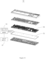
- Fig. 10 is a schematic perspective structural view of a keyboard of the present application
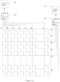
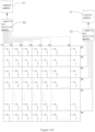
- Figs. 11a and 11b are schematic structural diagrams of a circuit of the keyboard shown in Fig. 10 , respectively.
- the keyboard 50 includes a control board 51, a capacitance detection module 53, a plurality of key modules 55 arranged in an array and a control module 57.
- the key modules 55 are arranged on the control board 51 in an array.
- the capacitance detection module 53 is arranged on the control board 51 and electrically connected with the key modules 55.
- the control module 57 correspondingly generates an input signal according to a detection result of the capacitance detection module 53.
- the key modules 55 include a circuit board, and as a further improvement, the control board 51 and the circuit board can be integrated into the same circuit board.
- the key module 55 can be any of the key modules 10, 20, 30 described above.
Landscapes
- Engineering & Computer Science (AREA)
- General Engineering & Computer Science (AREA)
- Theoretical Computer Science (AREA)
- Human Computer Interaction (AREA)
- Physics & Mathematics (AREA)
- General Physics & Mathematics (AREA)
- Push-Button Switches (AREA)
- Input From Keyboards Or The Like (AREA)
Applications Claiming Priority (3)
| Application Number | Priority Date | Filing Date | Title |
|---|---|---|---|
| CN202011312892.0A CN112332827A (zh) | 2020-11-20 | 2020-11-20 | 输入装置、输入方法及键盘 |
| CN202022722077.3U CN213547482U (zh) | 2020-11-20 | 2020-11-20 | 按键模组、输入装置及键盘 |
| PCT/CN2021/131776 WO2022105875A1 (zh) | 2020-11-20 | 2021-11-19 | 输入装置、输入方法及键盘 |
Publications (2)
| Publication Number | Publication Date |
|---|---|
| EP4246809A1 true EP4246809A1 (de) | 2023-09-20 |
| EP4246809A4 EP4246809A4 (de) | 2024-04-17 |
Family
ID=81708392
Family Applications (1)
| Application Number | Title | Priority Date | Filing Date |
|---|---|---|---|
| EP21894022.9A Withdrawn EP4246809A4 (de) | 2020-11-20 | 2021-11-19 | Eingabevorrichtung, eingabeverfahren und tastatur |
Country Status (5)
| Country | Link |
|---|---|
| US (1) | US20230403008A1 (de) |
| EP (1) | EP4246809A4 (de) |
| JP (1) | JP2023541190A (de) |
| KR (1) | KR20230051150A (de) |
| WO (1) | WO2022105875A1 (de) |
Families Citing this family (2)
| Publication number | Priority date | Publication date | Assignee | Title |
|---|---|---|---|---|
| CN116301393B (zh) * | 2023-03-16 | 2026-01-23 | 深圳名龙堂数字有限公司 | 一种具有多层板的开放式键盘 |
| CN118098855B (zh) * | 2024-04-26 | 2024-08-09 | 基合半导体(宁波)有限公司 | 电容感应式按键、设备、移动距离检测方法及存储介质 |
Family Cites Families (14)
| Publication number | Priority date | Publication date | Assignee | Title |
|---|---|---|---|---|
| FR2625339A1 (fr) * | 1987-12-24 | 1989-06-30 | Pendar Sarl | Clavier informatique |
| US4857684A (en) * | 1988-10-25 | 1989-08-15 | W. H. Brady Co. | Capacitance membrane switchcore with intertrace capacitive coupling and/or intratrace capacitive coupling |
| FR2670635B1 (fr) * | 1990-12-13 | 1993-03-19 | Sextant Avionique | Dispositif de commutation a double mode de fonctionnement. |
| JP3628972B2 (ja) * | 2001-03-14 | 2005-03-16 | ニッタ株式会社 | 静電容量式センサ |
| JP2002340699A (ja) * | 2001-05-21 | 2002-11-27 | Mitsumi Electric Co Ltd | 静電容量センサー |
| TWI497380B (zh) * | 2012-04-05 | 2015-08-21 | Ite Tech Inc | 電容式觸控按鍵及其操作方法 |
| CN203278792U (zh) * | 2013-05-30 | 2013-11-06 | 深圳市祈锦通信技术有限公司 | 通过电容触摸检测芯片实现机械按键开关功能的结构 |
| KR102066523B1 (ko) * | 2015-01-19 | 2020-01-15 | 썬전 리츠 이노베이션 테크놀로지 컴퍼니 리미티드 | 입력 장치 및 그 입력 조작 방법 |
| JP2016177339A (ja) * | 2015-03-18 | 2016-10-06 | アルプス電気株式会社 | 入力装置 |
| CN207074995U (zh) * | 2017-06-05 | 2018-03-06 | 深圳市力驰创新科技有限公司 | 静电容式机械按键开关 |
| CN207339812U (zh) * | 2017-06-05 | 2018-05-08 | 深圳市力驰创新科技有限公司 | 电容式按键开关 |
| CN210604839U (zh) * | 2019-08-19 | 2020-05-22 | 深圳市力驰创新科技有限公司 | 检测系统 |
| JP2021140901A (ja) * | 2020-03-03 | 2021-09-16 | オムロン株式会社 | スイッチ装置及びキー入力装置 |
| CN112332827A (zh) * | 2020-11-20 | 2021-02-05 | 深圳市力驰创新科技有限公司 | 输入装置、输入方法及键盘 |
-
2021
- 2021-11-19 EP EP21894022.9A patent/EP4246809A4/de not_active Withdrawn
- 2021-11-19 JP JP2023516743A patent/JP2023541190A/ja active Pending
- 2021-11-19 US US18/035,804 patent/US20230403008A1/en not_active Abandoned
- 2021-11-19 KR KR1020237001006A patent/KR20230051150A/ko not_active Ceased
- 2021-11-19 WO PCT/CN2021/131776 patent/WO2022105875A1/zh not_active Ceased
Also Published As
| Publication number | Publication date |
|---|---|
| JP2023541190A (ja) | 2023-09-28 |
| WO2022105875A1 (zh) | 2022-05-27 |
| US20230403008A1 (en) | 2023-12-14 |
| KR20230051150A (ko) | 2023-04-17 |
| EP4246809A4 (de) | 2024-04-17 |
Similar Documents
| Publication | Publication Date | Title |
|---|---|---|
| US7499025B2 (en) | Pressing direction sensor and input device using the same | |
| CN112332827A (zh) | 输入装置、输入方法及键盘 | |
| US8497786B2 (en) | Capacitive keyboard with enhanced electrode areas | |
| US11418193B2 (en) | Key unit and keyboard using the same | |
| EP4246809A1 (de) | Eingabevorrichtung, eingabeverfahren und tastatur | |
| JPH0562408B2 (de) | ||
| JP6246111B2 (ja) | 静電容量型入力装置 | |
| KR20070094900A (ko) | 방향 검지 스위치 | |
| CN213547482U (zh) | 按键模组、输入装置及键盘 | |
| WO2025031278A1 (zh) | 开关装置和电子设备 | |
| CN218182100U (zh) | 按键模组、键盘及输入装置 | |
| CN104579294A (zh) | 电容式按键单元及采用所述按键单元的键盘 | |
| CN112614720A (zh) | 按键组件和电子设备 | |
| CN213546179U (zh) | 按键模组、输入装置及鼠标 | |
| CN113539722B (zh) | 按键模组及电子设备 | |
| KR101000540B1 (ko) | 휴대장치용 입력장치 | |
| CN220872990U (zh) | 触压感应模组、耳机及电子装置 | |
| CN204539114U (zh) | 电容式按键单元及采用所述按键单元的键盘 | |
| CN214012804U (zh) | 轻触开关、输入装置及键盘 | |
| CN218298959U (zh) | 电容触摸皮套键盘 | |
| US10312909B2 (en) | Input device and input operation method thereof | |
| CN211557245U (zh) | 键盘 | |
| CN204539113U (zh) | 电容式按键单元及采用所述按键单元的键盘 | |
| CN115145404B (zh) | 输入装置及采用所述输入装置的控制方法 | |
| CN217690905U (zh) | 按键和键盘 |
Legal Events
| Date | Code | Title | Description |
|---|---|---|---|
| STAA | Information on the status of an ep patent application or granted ep patent |
Free format text: STATUS: THE INTERNATIONAL PUBLICATION HAS BEEN MADE |
|
| PUAI | Public reference made under article 153(3) epc to a published international application that has entered the european phase |
Free format text: ORIGINAL CODE: 0009012 |
|
| STAA | Information on the status of an ep patent application or granted ep patent |
Free format text: STATUS: REQUEST FOR EXAMINATION WAS MADE |
|
| 17P | Request for examination filed |
Effective date: 20230615 |
|
| AK | Designated contracting states |
Kind code of ref document: A1 Designated state(s): AL AT BE BG CH CY CZ DE DK EE ES FI FR GB GR HR HU IE IS IT LI LT LU LV MC MK MT NL NO PL PT RO RS SE SI SK SM TR |
|
| DAV | Request for validation of the european patent (deleted) | ||
| DAX | Request for extension of the european patent (deleted) | ||
| A4 | Supplementary search report drawn up and despatched |
Effective date: 20240315 |
|
| RIC1 | Information provided on ipc code assigned before grant |
Ipc: H03K 17/955 20060101AFI20240311BHEP |
|
| STAA | Information on the status of an ep patent application or granted ep patent |
Free format text: STATUS: THE APPLICATION HAS BEEN WITHDRAWN |
|
| 18W | Application withdrawn |
Effective date: 20240920 |