EP4246861B1 - Procédés, dispositifs et medium lisible par ordinateur pour la configuration des ressources de la liaison montante - Google Patents
Procédés, dispositifs et medium lisible par ordinateur pour la configuration des ressources de la liaison montante Download PDFInfo
- Publication number
- EP4246861B1 EP4246861B1 EP23174229.7A EP23174229A EP4246861B1 EP 4246861 B1 EP4246861 B1 EP 4246861B1 EP 23174229 A EP23174229 A EP 23174229A EP 4246861 B1 EP4246861 B1 EP 4246861B1
- Authority
- EP
- European Patent Office
- Prior art keywords
- base station
- rrc
- wireless device
- uplink
- gnb
- Prior art date
- Legal status (The legal status is an assumption and is not a legal conclusion. Google has not performed a legal analysis and makes no representation as to the accuracy of the status listed.)
- Active
Links
Images


Classifications
-
- H—ELECTRICITY
- H04—ELECTRIC COMMUNICATION TECHNIQUE
- H04W—WIRELESS COMMUNICATION NETWORKS
- H04W76/00—Connection management
- H04W76/10—Connection setup
-
- H—ELECTRICITY
- H04—ELECTRIC COMMUNICATION TECHNIQUE
- H04L—TRANSMISSION OF DIGITAL INFORMATION, e.g. TELEGRAPHIC COMMUNICATION
- H04L5/00—Arrangements affording multiple use of the transmission path
- H04L5/0001—Arrangements for dividing the transmission path
- H04L5/0003—Two-dimensional division
- H04L5/0005—Time-frequency
- H04L5/0007—Time-frequency the frequencies being orthogonal, e.g. OFDM(A) or DMT
- H04L5/001—Time-frequency the frequencies being orthogonal, e.g. OFDM(A) or DMT the frequencies being arranged in component carriers
-
- H—ELECTRICITY
- H04—ELECTRIC COMMUNICATION TECHNIQUE
- H04L—TRANSMISSION OF DIGITAL INFORMATION, e.g. TELEGRAPHIC COMMUNICATION
- H04L5/00—Arrangements affording multiple use of the transmission path
- H04L5/003—Arrangements for allocating sub-channels of the transmission path
- H04L5/0044—Allocation of payload; Allocation of data channels, e.g. PDSCH or PUSCH
-
- H—ELECTRICITY
- H04—ELECTRIC COMMUNICATION TECHNIQUE
- H04L—TRANSMISSION OF DIGITAL INFORMATION, e.g. TELEGRAPHIC COMMUNICATION
- H04L5/00—Arrangements affording multiple use of the transmission path
- H04L5/003—Arrangements for allocating sub-channels of the transmission path
- H04L5/0053—Allocation of signalling, i.e. of overhead other than pilot signals
-
- H—ELECTRICITY
- H04—ELECTRIC COMMUNICATION TECHNIQUE
- H04W—WIRELESS COMMUNICATION NETWORKS
- H04W72/00—Local resource management
- H04W72/20—Control channels or signalling for resource management
-
- H—ELECTRICITY
- H04—ELECTRIC COMMUNICATION TECHNIQUE
- H04W—WIRELESS COMMUNICATION NETWORKS
- H04W72/00—Local resource management
- H04W72/20—Control channels or signalling for resource management
- H04W72/23—Control channels or signalling for resource management in the downlink direction of a wireless link, i.e. towards a terminal
-
- H—ELECTRICITY
- H04—ELECTRIC COMMUNICATION TECHNIQUE
- H04W—WIRELESS COMMUNICATION NETWORKS
- H04W72/00—Local resource management
- H04W72/20—Control channels or signalling for resource management
- H04W72/29—Control channels or signalling for resource management between an access point and the access point controlling device
-
- H—ELECTRICITY
- H04—ELECTRIC COMMUNICATION TECHNIQUE
- H04W—WIRELESS COMMUNICATION NETWORKS
- H04W76/00—Connection management
- H04W76/20—Manipulation of established connections
- H04W76/27—Transitions between radio resource control [RRC] states
-
- H—ELECTRICITY
- H04—ELECTRIC COMMUNICATION TECHNIQUE
- H04W—WIRELESS COMMUNICATION NETWORKS
- H04W8/00—Network data management
- H04W8/22—Processing or transfer of terminal data, e.g. status or physical capabilities
-
- H—ELECTRICITY
- H04—ELECTRIC COMMUNICATION TECHNIQUE
- H04W—WIRELESS COMMUNICATION NETWORKS
- H04W88/00—Devices specially adapted for wireless communication networks, e.g. terminals, base stations or access point devices
- H04W88/08—Access point devices
- H04W88/085—Access point devices with remote components
-
- H—ELECTRICITY
- H04—ELECTRIC COMMUNICATION TECHNIQUE
- H04W—WIRELESS COMMUNICATION NETWORKS
- H04W72/00—Local resource management
- H04W72/12—Wireless traffic scheduling
- H04W72/1263—Mapping of traffic onto schedule, e.g. scheduled allocation or multiplexing of flows
- H04W72/1268—Mapping of traffic onto schedule, e.g. scheduled allocation or multiplexing of flows of uplink data flows
Definitions
- This application relates to the field of wireless communication systems such as 4G communication systems (e.g., LTE, LTE-Advanced), 5G communication systems, other communication systems compatible with 4G and/or 5G communication systems, and related methods, systems and apparatuses.
- 4G communication systems e.g., LTE, LTE-Advanced
- 5G communication systems other communication systems compatible with 4G and/or 5G communication systems, and related methods, systems and apparatuses.
- embodiments of the present application provide a method, an apparatus and a non-transitory computer-readable medium according to the enclosed independent claims.
- Advantageous features of the present invention are defined in the corresponding subclaims.
- Embodiments may be configured to operate as needed.
- the disclosed mechanism may be performed when certain criteria are met, for example, in a wireless device, a base station, a radio environment, a network, a combination of the above, and/or the like.
- Example criteria may be based, at least in part, on for example, wireless device or network node configurations, traffic load, initial system set up, packet sizes, traffic characteristics, a combination of the above, and/or the like.
- various example embodiments may be applied. Therefore, it may be possible to implement example embodiments that selectively implement disclosed protocols.
- a base station may communicate with a mix of wireless devices.
- Wireless devices and/or base stations may support multiple technologies, and/or multiple releases of the same technology.
- Wireless devices may have some specific capability(ies) depending on wireless device category and/or capability(ies).
- this disclosure may refer to a subset of the total wireless devices in a coverage area.
- This disclosure may refer to, for example, a plurality of wireless devices of a given LTE or 5G release with a given capability and in a given sector of the base station.
- the plurality of wireless devices in this disclosure may refer to a selected plurality of wireless devices, and/or a subset of total wireless devices in a coverage area which perform according to disclosed methods, and/or the like.
- There may be a plurality of base stations or a plurality of wireless devices in a coverage area that may not comply with the disclosed methods, for example, those wireless devices or base stations may perform based on older releases of LTE or 5G technology.
- a and B are sets and every element of A is an element of B, A is called a subset of B.
- A is called a subset of B.
- possible subsets of B ⁇ cell1, cell2 ⁇ are: ⁇ cell1 ⁇ , ⁇ cell2 ⁇ , and ⁇ cell1, cell2 ⁇ .
- the phrase "based on” is indicative that the phrase following the term "based on” is an example of one of a multitude of suitable possibilities that may, or may not, be employed to one or more of the various embodiments.
- the phrase "in response to” is indicative that the phrase following the phrase “in response to” is an example of one of a multitude of suitable possibilities that may, or may not, be employed to one or more of the various embodiments.
- the phrase “depending on” is indicative that the phrase following the phrase “depending on” is an example of one of a multitude of suitable possibilities that may, or may not, be employed to one or more of the various embodiments.
- the phrase “employing/using” (or equally “employing/using at least”) is indicative that the phrase following the phrase “employing/using” is an example of one of a multitude of suitable possibilities that may, or may not, be employed to one or more of the various embodiments.
- the term configured may relate to the capacity of a device whether the device is in an operational or non-operational state.
- Configured may refer to specific settings in a device that effect the operational characteristics of the device whether the device is in an operational or non-operational state.
- the hardware, software, firmware, registers, memory values, and/or the like may be "configured” within a device, whether the device is in an operational or nonoperational state, to provide the device with specific characteristics.
- Terms such as "a control message to cause in a device” may mean that a control message has parameters that may be used to configure specific characteristics or may be used to implement certain actions in the device, whether the device is in an operational or nonoperational state.
- parameters may comprise one or more information objects, and an information object may comprise one or more other objects.
- an information object may comprise one or more other objects.
- parameter (IE) N comprises parameter (IE) M
- parameter (IE) M comprises parameter (IE) K
- parameter (IE) K comprises parameter (information element) J.
- N comprises K
- N comprises J.
- one or more messages comprise a plurality of parameters
- modules may be possible to implement modules using physical hardware that incorporates discrete or programmable analog, digital and/or quantum hardware.
- programmable hardware comprise: computers, microcontrollers, microprocessors, application-specific integrated circuits (ASICs); field programmable gate arrays (FPGAs); and complex programmable logic devices (CPLDs).
- Computers, microcontrollers and microprocessors are programmed using languages such as assembly, C, C++ or the like.
- FPGAs, ASICs and CPLDs are often programmed using hardware description languages (HDL) such as VHSIC hardware description language (VHDL) or Verilog that configure connections between internal hardware modules with lesser functionality on a programmable device.
- HDL hardware description languages
- VHDL VHSIC hardware description language
- Verilog Verilog
- the CN 102 may provide the wireless device 106 with an interface to one or more data networks (DNs), such as public DNs (e.g., the Internet), private DNs, and/or intra-operator DNs.
- DNs data networks
- the CN 102 may set up end-to-end connections between the wireless device 106 and the one or more DNs, authenticate the wireless device 106, and provide charging functionality.
- one or more of the base stations in the RAN 104 may be implemented as a sectored site with more or less than three sectors.
- One or more of the base stations in the RAN 104 may be implemented as an access point, as a baseband processing unit coupled to several remote radio heads (RRHs), and/or as a repeater or relay node used to extend the coverage area of a donor node.
- RRHs remote radio heads
- a baseband processing unit coupled to RRHs may be part of a centralized or cloud RAN architecture, where the baseband processing unit may be either centralized in a pool of baseband processing units or virtualized.
- 3GPP The Third-Generation Partnership Project (3GPP) was formed in 1998 to provide global standardization of specifications for mobile communication networks similar to the mobile communication network 100 in FIG. 1A .
- 3GPP has produced specifications for three generations of mobile networks: a third generation (3G) network known as Universal Mobile Telecommunications System (UMTS), a fourth generation (4G) network known as Long-Term Evolution (LTE), and a fifth generation (5G) network known as 5G System (5GS).
- UMTS Universal Mobile Telecommunications System
- 4G fourth generation
- LTE Long-Term Evolution
- 5G 5G System
- Embodiments of the present disclosure are described with reference to the RAN of a 3GPP 5G network, referred to as next-generation RAN (NG-RAN).
- NG-RAN next-generation RAN
- Embodiments may be applicable to RANs of other mobile communication networks, such as the RAN 104 in FIG.
- the 5G-CN 152 includes an Access and Mobility Management Function (AMF) 158A and a User Plane Function (UPF) 158B, which are shown as one component AMF/UPF 158 in FIG. 1B for ease of illustration.
- AMF Access and Mobility Management Function
- UPF User Plane Function
- the UPF 158B may serve as a gateway between the NG-RAN 154 and the one or more DNs.
- the NG-RAN 154 may connect the 5G-CN 152 to the UEs 156 through radio communications over the air interface.
- the NG-RAN 154 may include one or more gNBs, illustrated as gNB 160A and gNB 160B (collectively gNBs 160) and/or one or more ng-eNBs, illustrated as ng-eNB 162A and ng-eNB 162B (collectively ng-eNBs 162).
- the gNBs 160 and ng-eNBs 162 may be more generically referred to as base stations.
- the gNBs 160 and ng-eNBs 162 may include one or more sets of antennas for communicating with the UEs 156 over an air interface.
- FIG. 2A and FIG. 2B respectively illustrate examples of NR user plane and NR control plane protocol stacks for the Uu interface that lies between a UE 210 and a gNB 220.
- the protocol stacks illustrated in FIG. 2A and FIG. 2B may be the same or similar to those used for the Uu interface between, for example, the UE 156A and the gNB 160A shown in FIG. 1B .
- the PDCPs 214 and 224 may perform header compression/decompression to reduce the amount of data that needs to be transmitted over the air interface, ciphering/deciphering to prevent unauthorized decoding of data transmitted over the air interface, and integrity protection (to ensure control messages originate from intended sources.
- the PDCPs 214 and 224 may perform retransmissions of undelivered packets, in-sequence delivery and reordering of packets, and removal of packets received in duplicate due to, for example, an intra-gNB handover.
- the PDCPs 214 and 224 may perform packet duplication to improve the likelihood of the packet being received and, at the receiver, remove any duplicate packets. Packet duplication may be useful for services that require high reliability.
- PDCPs 214 and 224 may perform mapping/demapping between a split radio bearer and RLC channels in a dual connectivity scenario.
- Dual connectivity is a technique that allows a UE to connect to two cells or, more generally, two cell groups: a master cell group (MCG) and a secondary cell group (SCG).
- MCG master cell group
- SCG secondary cell group
- a split bearer is when a single radio bearer, such as one of the radio bearers provided by the PDCPs 214 and 224 as a service to the SDAPs 215 and 225, is handled by cell groups in dual connectivity.
- the PDCPs 214 and 224 may map/de-map the split radio bearer between RLC channels belonging to cell groups.
- FIG. 4B illustrates an example format of a MAC subheader in a MAC PDU.
- the MAC subheader includes: an SDU length field for indicating the length (e.g., in bytes) of the MAC SDU to which the MAC subheader corresponds; a logical channel identifier (LCID) field for identifying the logical channel from which the MAC SDU originated to aid in the demultiplexing process; a flag (F) for indicating the size of the SDU length field; and a reserved bit (R) field for future use.
- SDU length field for indicating the length (e.g., in bytes) of the MAC SDU to which the MAC subheader corresponds
- LCID logical channel identifier
- F flag
- R reserved bit
- FIG. 4B further illustrates MAC control elements (CEs) inserted into the MAC PDU by a MAC, such as MAC 223 or MAC 222.
- a MAC such as MAC 223 or MAC 222.
- FIG. 4B illustrates two MAC CEs inserted into the MAC PDU.
- MAC CEs may be inserted at the beginning of a MAC PDU for downlink transmissions (as shown in FIG. 4B ) and at the end of a MAC PDU for uplink transmissions.
- MAC CEs may be used for in-band control signaling.
- Example MAC CEs include: scheduling-related MAC CEs, such as buffer status reports and power headroom reports; activation/deactivation MAC CEs, such as those for activation/deactivation of PDCP duplication detection, channel state information (CSI) reporting, sounding reference signal (SRS) transmission, and prior configured components; discontinuous reception (DRX) related MAC CEs; timing advance MAC CEs; and random access related MAC CEs.
- a MAC CE may be preceded by a MAC subheader with a similar format as described for MAC SDUs and may be identified with a reserved value in the LCID field that indicates the type of control information included in the MAC CE.
- logical channels, transport channels, and physical channels are first described as well as a mapping between the channel types.
- One or more of the channels may be used to carry out functions associated with the NR control plane protocol stack described later below.
- FIG. 5A and FIG. 5B illustrate, for downlink and uplink respectively, a mapping between logical channels, transport channels, and physical channels.
- Information is passed through channels between the RLC, the MAC, and the PHY of the NR protocol stack.
- a logical channel may be used between the RLC and the MAC and may be classified as a control channel that carries control and configuration information in the NR control plane or as a traffic channel that carries data in the NR user plane.
- a logical channel may be classified as a dedicated logical channel that is dedicated to a specific UE or as a common logical channel that may be used by more than one UE.
- a logical channel may also be defined by the type of information it carries.
- the set of logical channels defined by NR include, for example:
- Transport channels are used between the MAC and PHY layers and may be defined by how the information they carry is transmitted over the air interface.
- the set of transport channels defined by NR include, for example:
- the physical layer Similar to the physical control channels, the physical layer generates physical signals to support the low-level operation of the physical layer.
- the physical layer signals defined by NR include: primary synchronization signals (PSS), secondary synchronization signals (SSS), channel state information reference signals (CSI-RS), demodulation reference signals (DMRS), sounding reference signals (SRS), and phasetracking reference signals (PT-RS). These physical layer signals will be described in greater detail below.
- the NAS protocols 217 and 237 may provide control plane functionality between the UE 210 and the AMF 230 (e.g., the AMF 158A) or, more generally, between the UE 210 and the CN.
- the NAS protocols 217 and 237 may provide control plane functionality between the UE 210 and the AMF 230 via signaling messages, referred to as NAS messages. There is no direct path between the UE 210 and the AMF 230 through which the NAS messages can be transported.
- the NAS messages may be transported using the AS of the Uu and NG interfaces.
- NAS protocols 217 and 237 may provide control plane functionality such as authentication, security, connection setup, mobility management, and session management.
- the RRCs 216 and 226 may provide control plane functionality between the UE 210 and the gNB 220 or, more generally, between the UE 210 and the RAN.
- the RRCs 216 and 226 may provide control plane functionality between the UE 210 and the gNB 220 via signaling messages, referred to as RRC messages.
- RRC messages may be transmitted between the UE 210 and the RAN using signaling radio bearers and the same/similar PDCP, RLC, MAC, and PHY protocol layers.
- the MAC may multiplex control-plane and user-plane data into the same transport block (TB).
- the RRCs 216 and 226 may provide control plane functionality such as: broadcast of system information related to AS and NAS; paging initiated by the CN or the RAN; establishment, maintenance and release of an RRC connection between the UE 210 and the RAN; security functions including key management; establishment, configuration, maintenance and release of signaling radio bearers and data radio bearers; mobility functions; QoS management functions; the UE measurement reporting and control of the reporting; detection of and recovery from radio link failure (RLF); and/or NAS message transfer.
- RRCs 216 and 226 may establish an RRC context, which may involve configuring parameters for communication between the UE 210 and the RAN.
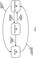
- FIG. 6 is an example diagram showing RRC state transitions of a UE.
- the UE may be the same or similar to the wireless device 106 depicted in FIG. 1A , the UE 210 depicted in FIG. 2A and FIG. 2B , or any other wireless device described in the present disclosure.
- a UE may be in at least one of three RRC states: RRC connected 602 (e.g., RRC_CONNECTED), RRC idle 604 (e.g., RRC_IDLE), and RRC inactive 606 (e.g., RRC_INACTIVE).
- RRC connected 602 e.g., RRC_CONNECTED
- RRC idle 604 e.g., RRC_IDLE
- RRC inactive 606 e.g., RRC_INACTIVE
- the UE has an established RRC context and may have at least one RRC connection with a base station.
- the base station may be similar to one of the one or more base stations included in the RAN 104 depicted in FIG. 1A , one of the gNBs 160 or ng-eNBs 162 depicted in FIG. 1B , the gNB 220 depicted in FIG. 2A and FIG. 2B , or any other base station described in the present disclosure.
- the base station with which the UE is connected may have the RRC context for the UE.
- the RRC context referred to as the UE context, may comprise parameters for communication between the UE and the base station.
- These parameters may include, for example: one or more AS contexts; one or more radio link configuration parameters; bearer configuration information (e.g., relating to a data radio bearer, signaling radio bearer, logical channel, QoS flow, and/or PDU session); security information; and/or PHY, MAC, RLC, PDCP, and/or SDAP layer configuration information.
- bearer configuration information e.g., relating to a data radio bearer, signaling radio bearer, logical channel, QoS flow, and/or PDU session
- security information e.g., relating to a data radio bearer, signaling radio bearer, logical channel, QoS flow, and/or PDU session
- PHY e.g., MAC, RLC, PDCP, and/or SDAP layer configuration information
- the RAN e.g., the RAN 104 or the NG-RAN 154
- the UE may measure the signal levels (e.g., reference signal levels) from a serving cell
- the UE's serving base station may request a handover to a cell of one of the neighboring base stations based on the reported measurements.
- the RRC state may transition from RRC connected 602 to RRC idle 604 through a connection release procedure 608 or to RRC inactive 606 through a connection inactivation procedure 610.
- RRC idle 604 an RRC context may not be established for the UE.
- the UE may not have an RRC connection with the base station.
- the UE may be in a sleep state for the majority of the time (e.g., to conserve battery power).
- the UE may wake up periodically (e.g., once in every discontinuous reception cycle) to monitor for paging messages from the RAN.
- Mobility of the UE may be managed by the UE through a procedure known as cell reselection.
- the RRC state may transition from RRC idle 604 to RRC connected 602 through a connection establishment procedure 612, which may involve a random access procedure as discussed in greater detail below.
- RRC inactive 606 the RRC context previously established is maintained in the UE and the base station. This allows for a fast transition to RRC connected 602 with reduced signaling overhead as compared to the transition from RRC idle 604 to RRC connected 602.
- the UE While in RRC inactive 606, the UE may be in a sleep state and mobility of the UE may be managed by the UE through cell reselection.
- the RRC state may transition from RRC inactive 606 to RRC connected 602 through a connection resume procedure 614 or to RRC idle 604 though a connection release procedure 616 that may be the same as or similar to connection release procedure 608.
- An RRC state may be associated with a mobility management mechanism.
- RRC idle 604 and RRC inactive 606 mobility is managed by the UE through cell reselection.
- the purpose of mobility management in RRC idle 604 and RRC inactive 606 is to allow the network to be able to notify the UE of an event via a paging message without having to broadcast the paging message over the entire mobile communications network.
- the mobility management mechanism used in RRC idle 604 and RRC inactive 606 may allow the network to track the UE on a cell-group level so that the paging message may be broadcast over the cells of the cell group that the UE currently resides within instead of the entire mobile communication network.
- the mobility management mechanisms for RRC idle 604 and RRC inactive 606 track the UE on a cell-group level. They may do so using different granularities of grouping. For example, there may be three levels of cell-grouping granularity: individual cells; cells within a RAN area identified by a RAN area identifier (RAI); and cells within a group of RAN areas, referred to as a tracking area and identified by a tracking area identifier (TAI).
- RAI RAN area identifier
- TAI tracking area and identified by a tracking area identifier
- Tracking areas may be used to track the UE at the CN level.
- the CN e.g., the CN 102 or the 5G-CN 152 may provide the UE with a list of TAIs associated with a UE registration area. If the UE moves, through cell reselection, to a cell associated with a TAI not included in the list of TAIs associated with the UE registration area, the UE may perform a registration update with the CN to allow the CN to update the UE's location and provide the UE with a new the UE registration area.
- RAN areas may be used to track the UE at the RAN level.
- the UE may be assigned a RAN notification area.
- a RAN notification area may comprise one or more cell identities, a list of RAIs, or a list of TAIs.
- a base station may belong to one or more RAN notification areas.
- a cell may belong to one or more RAN notification areas. If the UE moves, through cell reselection, to a cell not included in the RAN notification area assigned to the UE, the UE may perform a notification area update with the RAN to update the UE's RAN notification area.
- a gNB such as gNBs 160 in FIG. 1B , may be split in two parts: a central unit (gNB-CU), and one or more distributed units (gNB-DU).
- a gNB-CU may be coupled to one or more gNB-DUs using an F1 interface.
- the gNB-CU may comprise the RRC, the PDCP, and the SDAP.
- a gNB-DU may comprise the RLC, the MAC, and the PHY.
- OFDM orthogonal frequency divisional multiplexing
- FAM frequency divisional multiplexing
- F-QAM M-quadrature amplitude modulation
- M-PSK M-phase shift keying
- source symbols e.g., M-quadrature amplitude modulation (M-QAM) or M-phase shift keying (M-PSK) symbols
- source symbols e.g., M-quadrature amplitude modulation (M-QAM) or M-phase shift keying (M-PSK) symbols
- source symbols e.g., M-quadrature amplitude modulation (M-QAM) or M-phase shift keying (M-PSK) symbols
- source symbols e.g., M-quadrature amplitude modulation (M-QAM) or M-phase shift keying (M-PSK) symbols
- source symbols e.g., M-quadrature amplitude modulation (M-QAM) or M-phase shift keying (M-PSK) symbols
- source symbols
- the IFFT block may take in F source symbols at a time, one from each of the F parallel symbol streams, and use each source symbol to modulate the amplitude and phase of one of F sinusoidal basis functions that correspond to the F orthogonal subcarriers.
- the output of the IFFT block may be F time-domain samples that represent the summation of the F orthogonal subcarriers.
- the F time-domain samples may form a single OFDM symbol.
- an OFDM symbol provided by the IFFT block may be transmitted over the air interface on a carrier frequency.
- the F parallel symbol streams may be mixed using an FFT block before being processed by the IFFT block.
- This operation produces Discrete Fourier Transform (DFT)-precoded OFDM symbols and may be used by UEs in the uplink to reduce the peak to average power ratio (PAPR).
- DFT Discrete Fourier Transform
- PAPR peak to average power ratio
- Inverse processing may be performed on the OFDM symbol at a receiver using an FFT block to recover the data mapped to the source symbols.
- FIG. 7 illustrates an example configuration of an NR frame into which OFDM symbols are grouped.
- An NR frame may be identified by a system frame number (SFN).
- the SFN may repeat with a period of 1024 frames.
- one NR frame may be 10 milliseconds (ms) in duration and may include 10 subframes that are 1 ms in duration.
- a subframe may be divided into slots that include, for example, 14 OFDM symbols per slot.
- the duration of a slot may depend on the numerology used for the OFDM symbols of the slot.
- a flexible numerology is supported to accommodate different cell deployments (e.g., cells with carrier frequencies below 1 GHz up to cells with carrier frequencies in the mm-wave range).
- a numerology may be defined in terms of subcarrier spacing and cyclic prefix duration.
- subcarrier spacings may be scaled up by powers of two from a baseline subcarrier spacing of 15 kHz
- cyclic prefix durations may be scaled down by powers of two from a baseline cyclic prefix duration of 4.7 ⁇ s.
- NR defines numerologies with the following subcarrier spacing/cyclic prefix duration combinations: 15 kHz/4.7 ⁇ s; 30 kHz/2.3 ⁇ s; 60 kHz/1.2 ⁇ s; 120 kHz/0.59 ⁇ s; and 240 kHz/0.29 ⁇ s.
- a slot may have a fixed number of OFDM symbols (e.g., 14 OFDM symbols).
- a numerology with a higher subcarrier spacing has a shorter slot duration and, correspondingly, more slots per subframe.
- FIG. 7 illustrates this numerology-dependent slot duration and slots-per-subframe transmission structure (the numerology with a subcarrier spacing of 240 kHz is not shown in FIG. 7 for ease of illustration).
- a subframe in NR may be used as a numerology-independent time reference, while a slot may be used as the unit upon which uplink and downlink transmissions are scheduled.
- scheduling in NR may be decoupled from the slot duration and start at any OFDM symbol and last for as many symbols as needed for a transmission. These partial slot transmissions may be referred to as mini-slot or subslot transmissions.
- FIG. 8 illustrates an example configuration of a slot in the time and frequency domain for an NR carrier.
- the slot includes resource elements (REs) and resource blocks (RBs).
- An RE is the smallest physical resource in NR.
- An RE spans one OFDM symbol in the time domain by one subcarrier in the frequency domain as shown in FIG. 8 .
- An RB spans twelve consecutive REs in the frequency domain as shown in FIG. 8 .
- Such a limitation may limit the NR carrier to 50, 100, 200, and 400 MHz for subcarrier spacings of 15, 30, 60, and 120 kHz, respectively, where the 400 MHz bandwidth may be set based on a 400 MHz per carrier bandwidth limit.
- FIG. 8 illustrates a single numerology being used across the entire bandwidth of the NR carrier.
- multiple numerologies may be supported on the same carrier.
- NR may support wide carrier bandwidths (e.g., up to 400 MHz for a subcarrier spacing of 120 kHz). Not all UEs may be able to receive the full carrier bandwidth (e.g., due to hardware limitations). Also, receiving the full carrier bandwidth may be prohibitive in terms of UE power consumption. In an example, to reduce power consumption and/or for other purposes, a UE may adapt the size of the UE's receive bandwidth based on the amount of traffic the UE is scheduled to receive. This is referred to as bandwidth adaptation.
- NR defines bandwidth parts (BWPs) to support UEs not capable of receiving the full carrier bandwidth and to support bandwidth adaptation.
- BWP may be defined by a subset of contiguous RBs on a carrier.
- a UE may be configured (e.g., via RRC layer) with one or more downlink BWPs and one or more uplink BWPs per serving cell (e.g., up to four downlink BWPs and up to four uplink BWPs per serving cell).
- one or more of the configured BWPs for a serving cell may be active. These one or more BWPs may be referred to as active BWPs of the serving cell.
- the serving cell When a serving cell is configured with a secondary uplink carrier, the serving cell may have one or more first active BWPs in the uplink carrier and one or more second active BWPs in the secondary uplink carrier.
- a downlink BWP from a set of configured downlink BWPs may be linked with an uplink BWP from a set of configured uplink BWPs if a downlink BWP index of the downlink BWP and an uplink BWP index of the uplink BWP are the same.
- a UE may expect that a center frequency for a downlink BWP is the same as a center frequency for an uplink BWP.
- a base station may configure a UE with one or more control resource sets (CORESETs) for at least one search space.
- CORESETs control resource sets
- a search space is a set of locations in the time and frequency domains where the UE may find control information.
- the search space may be a UE-specific search space or a common search space (potentially usable by a plurality of UEs).
- a base station may configure a UE with a common search space, on a PCell or on a primary secondary cell (PSCell), in an active downlink BWP.
- a base station may semi-statically configure a UE with a default downlink BWP within a set of configured downlink BWPs associated with a PCell. If the base station does not provide the default downlink BWP to the UE, the default downlink BWP may be an initial active downlink BWP. The UE may determine which BWP is the initial active downlink BWP based on a CORESET configuration obtained using the PBCH.
- a base station may configure a UE with a BWP inactivity timer value for a PCell.
- the UE may start or restart a BWP inactivity timer at any appropriate time.
- the UE may start or restart the BWP inactivity timer ( a ) when the UE detects a DCI indicating an active downlink BWP other than a default downlink BWP for a paired spectra operation; or (b) when a UE detects a DCI indicating an active downlink BWP or active uplink BWP other than a default downlink BWP or uplink BWP for an unpaired spectra operation.
- the UE may run the BWP inactivity timer toward expiration (for example, increment from zero to the BWP inactivity timer value, or decrement from the BWP inactivity timer value to zero).
- the UE may switch from the active downlink BWP to the default downlink BWP.
- a base station may semi-statically configure a UE with one or more BWPs.
- a UE may switch an active BWP from a first BWP to a second BWP in response to receiving a DCI indicating the second BWP as an active BWP and/or in response to an expiry of the BWP inactivity timer (e.g., if the second BWP is the default BWP).
- Downlink and uplink BWP switching may be performed independently in paired spectra. In unpaired spectra, downlink and uplink BWP switching may be performed simultaneously. Switching between configured BWPs may occur based on RRC signaling, DCI, expiration of a BWP inactivity timer, and/or an initiation of random access.
- FIG. 9 illustrates an example of bandwidth adaptation using three configured BWPs for an NR carrier.
- a UE configured with the three BWPs may switch from one BWP to another BWP at a switching point.
- the BWPs include: a BWP 902 with a bandwidth of 40 MHz and a subcarrier spacing of 15 kHz; a BWP 904 with a bandwidth of 10 MHz and a subcarrier spacing of 15 kHz; and a BWP 906 with a bandwidth of 20 MHz and a subcarrier spacing of 60 kHz.
- the BWP 902 may be an initial active BWP
- the BWP 904 may be a default BWP.
- the UE may switch between BWPs at switching points.
- the UE may switch from the BWP 902 to the BWP 904 at a switching point 908.
- the switching at the switching point 908 may occur for any suitable reason, for example, in response to an expiry of a BWP inactivity timer (indicating switching to the default BWP) and/or in response to receiving a DCI indicating BWP 904 as the active BWP.
- the UE may switch at a switching point 910 from active BWP 904 to BWP 906 in response receiving a DCI indicating BWP 906 as the active BWP.
- FIG. 10A illustrates the three CA configurations with two CCs.
- the two CCs are aggregated in the same frequency band (frequency band A) and are located directly adjacent to each other within the frequency band.
- the two CCs are aggregated in the same frequency band (frequency band A) and are separated in the frequency band by a gap.
- the two CCs are located in frequency bands (frequency band A and frequency band B).
- up to 32 CCs may be aggregated.
- the aggregated CCs may have the same or different bandwidths, subcarrier spacing, and/or duplexing schemes (TDD or FDD).
- a serving cell for a UE using CA may have a downlink CC.
- one or more uplink CCs may be optionally configured for a serving cell.
- the ability to aggregate more downlink carriers than uplink carriers may be useful, for example, when the UE has more data traffic in the downlink than in the uplink.
- one of the aggregated cells for a UE may be referred to as a primary cell (PCell).
- the PCell may be the serving cell that the UE initially connects to at RRC connection establishment, reestablishment, and/or handover.
- the PCell may provide the UE with NAS mobility information and the security input.
- UEs may have different PCells.
- the carrier corresponding to the PCell may be referred to as the downlink primary CC (DL PCC).
- the carrier corresponding to the PCell may be referred to as the uplink primary CC (UL PCC).
- SCells secondary cells
- Configured SCells for a UE may be activated and deactivated based on, for example, traffic and channel conditions. Deactivation of an SCell may mean that PDCCH and PDSCH reception on the SCell is stopped and PUSCH, SRS, and CQI transmissions on the SCell are stopped. Configured SCells may be activated and deactivated using a MAC CE with respect to FIG. 4B . For example, a MAC CE may use a bitmap (e.g., one bit per SCell) to indicate which SCells (e.g., in a subset of configured SCells) for the UE are activated or deactivated. Configured SCells may be deactivated in response to an expiration of an SCell deactivation timer (e.g., one SCell deactivation timer per SCell).
- an SCell deactivation timer e.g., one SCell deactivation timer per SCell.
- FIG. 10B illustrates an example of how aggregated cells may be configured into one or more PUCCH groups.
- a PUCCH group 1010 and a PUCCH group 1050 may include one or more downlink CCs, respectively.
- the PUCCH group 1010 includes three downlink CCs: a PCell 1011, an SCell 1012, and an SCell 1013.
- the PUCCH group 1050 includes three downlink CCs in the present example: a PCell 1051, an SCell 1052, and an SCell 1053.
- One or more uplink CCs may be configured as a PCell 1021, an SCell 1022, and an SCell 1023.
- One or more other uplink CCs may be configured as a primary Scell (PSCell) 1061, an SCell 1062, and an SCell 1063.
- Uplink control information (UCI) related to the downlink CCs of the PUCCH group 1010 shown as UCI 1031, UCI 1032, and UCI 1033, may be transmitted in the uplink of the PCell 1021.
- Uplink control information (UCI) related to the downlink CCs of the PUCCH group 1050, shown as UCI 1071, UCI 1072, and UCI 1073, may be transmitted in the uplink of the PSCell 1061.
- a base station may transmit (e.g., unicast, multicast, and/or broadcast) one or more Reference Signals (RSs) to a UE (e.g., PSS, SSS, CSI-RS, DMRS, and/or PT-RS, as shown in FIG. 5A ).
- RSs Reference Signals
- the UE may transmit one or more RSs to the base station (e.g., DMRS, PT-RS, and/or SRS, as shown in FIG. 5B ).
- the PSS and the SSS may be transmitted by the base station and used by the UE to synchronize the UE to the base station.
- the PSS and the SSS may be provided in a synchronization signal (SS) / physical broadcast channel (PBCH) block that includes the PSS, the SSS, and the PBCH.
- the base station may periodically transmit a burst of SS/PBCH blocks.
- 11A is an example, and that these parameters (number of SS/PBCH blocks per burst, periodicity of bursts, position of burst within the frame) may be configured based on, for example: a carrier frequency of a cell in which the SS/PBCH block is transmitted; a numerology or subcarrier spacing of the cell; a configuration by the network (e.g., using RRC signaling); or any other suitable factor.
- the UE may assume a subcarrier spacing for the SS/PBCH block based on the carrier frequency being monitored, unless the radio network configured the UE to assume a different subcarrier spacing.
- the SS/PBCH block may be a cell-defining SS block (CD-SSB).
- a primary cell may be associated with a CD-SSB.
- the CD-SSB may be located on a synchronization raster.
- a cell selection/search and/or reselection may be based on the CD-SSB.
- the SS/PBCH block may be used by the UE to determine one or more parameters of the cell. For example, the UE may determine a physical cell identifier (PCI) of the cell based on the sequences of the PSS and the SSS, respectively. The UE may determine a location of a frame boundary of the cell based on the location of the SS/PBCH block. For example, the SS/PBCH block may indicate that it has been transmitted in accordance with a transmission pattern, wherein a SS/PBCH block in the transmission pattern is a known distance from the frame boundary.
- PCI physical cell identifier
- the PBCH may use a QPSK modulation and may use forward error correction (FEC).
- FEC forward error correction
- the FEC may use polar coding.
- One or more symbols spanned by the PBCH may carry one or more DMRSs for demodulation of the PBCH.
- the PBCH may include an indication of a current system frame number (SFN) of the cell and/or a SS/PBCH block timing index. These parameters may facilitate time synchronization of the UE to the base station.
- the PBCH may include a master information block (MIB) used to provide the UE with one or more parameters.
- the MIB may be used by the UE to locate remaining minimum system information (RMSI) associated with the cell.
- the RMSI may include a System Information Block Type 1 (SIB1).
- the SIB1 may contain information needed by the UE to access the cell.
- the UE may use one or more parameters of the MIB to monitor PDCCH, which may be used to schedule PDSCH.
- the PDSCH may include the SIB1.
- the SIB1 may be decoded using parameters provided in the MIB.
- the PBCH may indicate an absence of SIB 1. Based on the PBCH indicating the absence of SIB1, the UE may be pointed to a frequency. The UE may search for an SS/PBCH block at the frequency to which the UE is pointed.
- the UE may assume that one or more SS/PBCH blocks transmitted with a same SS/PBCH block index are quasi co-located (QCLed) (e.g., having the same/similar Doppler spread, Doppler shift, average gain, average delay, and/or spatial Rx parameters).
- QCL quasi co-located
- SS/PBCH blocks may be transmitted in spatial directions (e.g., using different beams that span a coverage area of the cell).
- a first SS/PBCH block may be transmitted in a first spatial direction using a first beam
- a second SS/PBCH block may be transmitted in a second spatial direction using a second beam.
- a base station may transmit a plurality of SS/PBCH blocks.
- a first PCI of a first SS/PBCH block of the plurality of SS/PBCH blocks may be different from a second PCI of a second SS/PBCH block of the plurality of SS/PBCH blocks.
- the PCIs of SS/PBCH blocks transmitted in different frequency locations may be different or the same.
- the CSI-RS may be transmitted by the base station and used by the UE to acquire channel state information (CSI).
- the base station may configure the UE with one or more CSI-RSs for channel estimation or any other suitable purpose.
- the base station may configure a UE with one or more of the same/similar CSI-RSs.
- the UE may measure the one or more CSI-RSs.
- the UE may estimate a downlink channel state and/or generate a CSI report based on the measuring of the one or more downlink CSI-RSs.
- the UE may provide the CSI report to the base station.
- the base station may use feedback provided by the UE (e.g., the estimated downlink channel state) to perform link adaptation.
- the base station may semi-statically configure the UE with one or more CSI-RS resource sets.
- a CSI-RS resource may be associated with a location in the time and frequency domains and a periodicity.
- the base station may selectively activate and/or deactivate a CSI-RS resource.
- the base station may indicate to the UE that a CSI-RS resource in the CSI-RS resource set is activated and/or deactivated.
- the base station may configure the UE to report CSI measurements.
- the base station may configure the UE to provide CSI reports periodically, aperiodically, or semi-persistently.
- periodic CSI reporting the UE may be configured with a timing and/or periodicity of a plurality of CSI reports.
- the base station may request a CSI report.
- the base station may command the UE to measure a configured CSI-RS resource and provide a CSI report relating to the measurements.
- the base station may configure the UE to transmit periodically, and selectively activate or deactivate the periodic reporting.
- the base station may configure the UE with a CSI-RS resource set and CSI reports using RRC signaling.
- the CSI-RS configuration may comprise one or more parameters indicating, for example, up to 32 antenna ports.
- the UE may be configured to employ the same OFDM symbols for a downlink CSI-RS and a control resource set (CORESET) when the downlink CSI-RS and CORESET are spatially QCLed and resource elements associated with the downlink CSI-RS are outside of the physical resource blocks (PRBs) configured for the CORESET.
- the UE may be configured to employ the same OFDM symbols for downlink CSI-RS and SS/PBCH blocks when the downlink CSI-RS and SS/PBCH blocks are spatially QCLed and resource elements associated with the downlink CSI-RS are outside of PRBs configured for the SS/PBCH blocks.
- Downlink DMRSs may be transmitted by a base station and used by a UE for channel estimation.
- the downlink DMRS may be used for coherent demodulation of one or more downlink physical channels (e.g., PDSCH).
- An NR network may support one or more variable and/or configurable DMRS patterns for data demodulation.
- At least one downlink DMRS configuration may support a front-loaded DMRS pattern.
- a front-loaded DMRS may be mapped over one or more OFDM symbols (e.g., one or two adjacent OFDM symbols).
- a base station may semi-statically configure the UE with a number (e.g. a maximum number) of front-loaded DMRS symbols for PDSCH.
- a DMRS configuration may support one or more DMRS ports.
- a DMRS configuration may support up to eight orthogonal downlink DMRS ports per UE.
- a DMRS configuration may support up to 4 orthogonal downlink DMRS ports per UE.
- a radio network may support (e.g., at least for CP-OFDM) a common DMRS structure for downlink and uplink, wherein a DMRS location, a DMRS pattern, and/or a scrambling sequence may be the same or different.
- the base station may transmit a downlink DMRS and a corresponding PDSCH using the same precoding matrix.
- the UE may use the one or more downlink DMRSs for coherent demodulation/channel estimation of the PDSCH.
- a transmitter may use a precoder matrices for a part of a transmission bandwidth.
- the transmitter may use a first precoder matrix for a first bandwidth and a second precoder matrix for a second bandwidth.
- the first precoder matrix and the second precoder matrix may be different based on the first bandwidth being different from the second bandwidth.
- the UE may assume that a same precoding matrix is used across a set of PRBs.
- the set of PRBs may be denoted as a precoding resource block group (PRG).
- PRG precoding resource block group
- a PDSCH may comprise one or more layers.
- the UE may assume that at least one symbol with DMRS is present on a layer of the one or more layers of the PDSCH.
- a higher layer may configure up to 3 DMRSs for the PDSCH.
- Downlink PT-RS may be transmitted by a base station and used by a UE for phasenoise compensation. Whether a downlink PT-RS is present or not may depend on an RRC configuration. The presence and/or pattern of the downlink PT-RS may be configured on a UE-specific basis using a combination of RRC signaling and/or an association with one or more parameters employed for other purposes (e.g., modulation and coding scheme (MCS)), which may be indicated by DCI. When configured, a dynamic presence of a downlink PT-RS may be associated with one or more DCI parameters comprising at least MCS.
- An NR network may support a plurality of PT-RS densities defined in the time and/or frequency domains.
- a frequency domain density may be associated with at least one configuration of a scheduled bandwidth.
- the UE may assume a same precoding for a DMRS port and a PT-RS port.
- a number of PT-RS ports may be fewer than a number of DMRS ports in a scheduled resource.
- Downlink PT-RS may be confined in the scheduled time/frequency duration for the UE.
- Downlink PT-RS may be transmitted on symbols to facilitate phase tracking at the receiver.
- the UE may transmit an uplink DMRS to a base station for channel estimation.
- the base station may use the uplink DMRS for coherent demodulation of one or more uplink physical channels.
- the UE may transmit an uplink DMRS with a PUSCH and/or a PUCCH.
- the uplink DM-RS may span a range of frequencies that is similar to a range of frequencies associated with the corresponding physical channel.
- the base station may configure the UE with one or more uplink DMRS configurations. At least one DMRS configuration may support a front-loaded DMRS pattern.
- the front-loaded DMRS may be mapped over one or more OFDM symbols (e.g., one or two adjacent OFDM symbols).
- One or more uplink DMRSs may be configured to transmit at one or more symbols of a PUSCH and/or a PUCCH.
- the base station may semi-statically configure the UE with a number (e.g. maximum number) of front-loaded DMRS symbols for the PUSCH and/or the PUCCH, which the UE may use to schedule a single-symbol DMRS and/or a double-symbol DMRS.
- An NR network may support (e.g., for cyclic prefix orthogonal frequency division multiplexing (CP-OFDM)) a common DMRS structure for downlink and uplink, wherein a DMRS location, a DMRS pattern, and/or a scrambling sequence for the DMRS may be the same or different.
- CP-OFDM cyclic prefix orthogonal frequency division multiplexing
- a PUSCH may comprise one or more layers, and the UE may transmit at least one symbol with DMRS present on a layer of the one or more layers of the PUSCH.
- a higher layer may configure up to three DMRSs for the PUSCH.
- Uplink PT-RS (which may be used by a base station for phase tracking and/or phasenoise compensation) may or may not be present depending on an RRC configuration of the UE.
- the presence and/or pattern of uplink PT-RS may be configured on a UE-specific basis by a combination of RRC signaling and/or one or more parameters employed for other purposes (e.g., Modulation and Coding Scheme (MCS)), which may be indicated by DCI.
- MCS Modulation and Coding Scheme
- a dynamic presence of uplink PT-RS may be associated with one or more DCI parameters comprising at least MCS.
- a radio network may support a plurality of uplink PT-RS densities defined in time/frequency domain.
- a frequency domain density may be associated with at least one configuration of a scheduled bandwidth.
- the UE may assume a same precoding for a DMRS port and a PT-RS port.
- a number of PT-RS ports may be fewer than a number of DMRS ports in a scheduled resource.
- uplink PT-RS may be confined in the scheduled time/frequency duration for the UE.
- SRS may be transmitted by a UE to a base station for channel state estimation to support uplink channel dependent scheduling and/or link adaptation.
- SRS transmitted by the UE may allow a base station to estimate an uplink channel state at one or more frequencies.
- a scheduler at the base station may employ the estimated uplink channel state to assign one or more resource blocks for an uplink PUSCH transmission from the UE.
- the base station may semi-statically configure the UE with one or more SRS resource sets. For an SRS resource set, the base station may configure the UE with one or more SRS resources.
- An SRS resource set applicability may be configured by a higher layer (e.g., RRC) parameter.
- an SRS resource in a SRS resource set of the one or more SRS resource sets may be transmitted at a time instant (e.g., simultaneously).
- the UE may transmit one or more SRS resources in SRS resource sets.
- An NR network may support aperiodic, periodic and/or semi-persistent SRS transmissions.
- the UE may transmit SRS resources based on one or more trigger types, wherein the one or more trigger types may comprise higher layer signaling (e.g., RRC) and/or one or more DCI formats.
- At least one DCI format may be employed for the UE to select at least one of one or more configured SRS resource sets.
- An SRS trigger type 0 may refer to an SRS triggered based on a higher layer signaling.
- An SRS trigger type 1 may refer to an SRS triggered based on one or more DCI formats.
- the UE when PUSCH and SRS are transmitted in a same slot, the UE may be configured to transmit SRS after a transmission of a PUSCH and a corresponding uplink DMRS.
- the base station may semi-statically configure the UE with one or more SRS configuration parameters indicating at least one of following: a SRS resource configuration identifier; a number of SRS ports; time domain behavior of an SRS resource configuration (e.g., an indication of periodic, semi-persistent, or aperiodic SRS); slot, mini-slot, and/or subframe level periodicity; offset for a periodic and/or an aperiodic SRS resource; a number of OFDM symbols in an SRS resource; a starting OFDM symbol of an SRS resource; an SRS bandwidth; a frequency hopping bandwidth; a cyclic shift; and/or an SRS sequence ID.
- SRS resource configuration identifier e.g., an indication of periodic, semi-persistent, or aperiodic SRS
- slot, mini-slot, and/or subframe level periodicity e.g., an indication of periodic, semi-persistent, or aperiodic SRS
- An antenna port is defined such that the channel over which a symbol on the antenna port is conveyed can be inferred from the channel over which another symbol on the same antenna port is conveyed. If a first symbol and a second symbol are transmitted on the same antenna port, the receiver may infer the channel (e.g., fading gain, multipath delay, and/or the like) for conveying the second symbol on the antenna port, from the channel for conveying the first symbol on the antenna port.
- a first antenna port and a second antenna port may be referred to as quasi co-located (QCLed) if one or more large-scale properties of the channel over which a first symbol on the first antenna port is conveyed may be inferred from the channel over which a second symbol on a second antenna port is conveyed.
- the one or more large-scale properties may comprise at least one of: a delay spread; a Doppler spread; a Doppler shift; an average gain; an average delay; and/or spatial Receiving (Rx) parameters.
- Beam management may comprise beam measurement, beam selection, and beam indication.
- a beam may be associated with one or more reference signals.
- a beam may be identified by one or more beamformed reference signals.
- the UE may perform downlink beam measurement based on downlink reference signals (e.g., a channel state information reference signal (CSI-RS)) and generate a beam measurement report.
- CSI-RS channel state information reference signal
- the UE may perform the downlink beam measurement procedure after an RRC connection is set up with a base station.
- FIG. 11B illustrates an example of channel state information reference signals (CSI-RSs) that are mapped in the time and frequency domains.
- CSI-RSs channel state information reference signals
- a square shown in FIG. 11B may span a resource block (RB) within a bandwidth of a cell.
- a base station may transmit one or more RRC messages comprising CSI-RS resource configuration parameters indicating one or more CSI-RSs.
- One or more of the following parameters may be configured by higher layer signaling (e.g., RRC and/or MAC signaling) for a CSI-RS resource configuration: a CSI-RS resource configuration identity, a number of CSI-RS ports, a CSI-RS configuration (e.g., symbol and resource element (RE) locations in a subframe), a CSI-RS subframe configuration (e.g., subframe location, offset, and periodicity in a radio frame), a CSI-RS power parameter, a CSI-RS sequence parameter, a code division multiplexing (CDM) type parameter, a frequency density, a transmission comb, quasi co-location (QCL) parameters (e.g., QCL-scramblingidentity, crs-portscount, mbsfn-subframeconfiglist, csi-rs-configZPid, qcl-csi-rs-configNZPid), and/or other radio resource parameters.
- the three beams illustrated in FIG. 11B may be configured for a UE in a UE-specific configuration. Three beams are illustrated in FIG. 11B (beam #1, beam #2, and beam #3), more or fewer beams may be configured.
- Beam #1 may be allocated with CSI-RS 1101 that may be transmitted in one or more subcarriers in an RB of a first symbol.
- Beam #2 may be allocated with CSI-RS 1102 that may be transmitted in one or more subcarriers in an RB of a second symbol.
- Beam #3 may be allocated with CSI-RS 1103 that may be transmitted in one or more subcarriers in an RB of a third symbol.
- a base station may use other subcarriers in a same RB (for example, those that are not used to transmit CSI-RS 1101) to transmit another CSI-RS associated with a beam for another UE.
- FDM frequency division multiplexing
- TDM time domain multiplexing
- CSI-RSs such as those illustrated in FIG. 11B (e.g., CSI-RS 1101, 1102, 1103) may be transmitted by the base station and used by the UE for one or more measurements.
- the UE may measure a reference signal received power (RSRP) of configured CSI-RS resources.
- the base station may configure the UE with a reporting configuration and the UE may report the RSRP measurements to a network (for example, via one or more base stations) based on the reporting configuration.
- the base station may determine, based on the reported measurement results, one or more transmission configuration indication (TCI) states comprising a number of reference signals.
- TCI transmission configuration indication
- the base station may indicate one or more TCI states to the UE (e.g., via RRC signaling, a MAC CE, and/or a DCI).
- the UE may receive a downlink transmission with a receive (Rx) beam determined based on the one or more TCI states.
- the UE may or may not have a capability of beam correspondence. If the UE has the capability of beam correspondence, the UE may determine a spatial domain filter of a transmit (Tx) beam based on a spatial domain filter of the corresponding Rx beam. If the UE does not have the capability of beam correspondence, the UE may perform an uplink beam selection procedure to determine the spatial domain filter of the Tx beam.
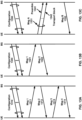
- FIG. 12A illustrates examples of three downlink beam management procedures: P1, P2, and P3.
- Procedure P1 may enable a UE measurement on transmit (Tx) beams of a transmission reception point (TRP) (or multiple TRPs), e.g., to support a selection of one or more base station Tx beams and/or UE Rx beams (shown as ovals in the top row and bottom row, respectively, of P1).
- Beamforming at a TRP may comprise a Tx beam sweep for a set of beams (shown, in the top rows of P1 and P2, as ovals rotated in a counter-clockwise direction indicated by the dashed arrow).
- FIG. 12B illustrates examples of three uplink beam management procedures: U1, U2, and U3.
- Procedure U1 may be used to enable a base station to perform a measurement on Tx beams of a UE, e.g., to support a selection of one or more UE Tx beams and/or base station Rx beams (shown as ovals in the top row and bottom row, respectively, of U1).
- Beamforming at the UE may include, e.g., a Tx beam sweep from a set of beams (shown in the bottom rows of U1 and U3 as ovals rotated in a clockwise direction indicated by the dashed arrow).
- Beamforming at the base station may include, e.g., an Rx beam sweep from a set of beams (shown, in the top rows of U1 and U2, as ovals rotated in a counter-clockwise direction indicated by the dashed arrow).
- Procedure U2 may be used to enable the base station to adjust its Rx beam when the UE uses a fixed Tx beam.
- the UE and/or the base station may perform procedure U2 using a smaller set of beams than is used in procedure P1, or using narrower beams than the beams used in procedure P1. This may be referred to as beam refinement
- the UE may perform procedure U3 to adjust its Tx beam when the base station uses a fixed Rx beam.
- a UE may initiate a beam failure recovery (BFR) procedure based on detecting a beam failure.
- the UE may transmit a BFR request (e.g., a preamble, a UCI, an SR, a MAC CE, and/or the like) based on the initiating of the BFR procedure.
- the UE may detect the beam failure based on a determination that a quality of beam pair link(s) of an associated control channel is unsatisfactory (e.g., having an error rate higher than an error rate threshold, a received signal power lower than a received signal power threshold, an expiration of a timer, and/or the like).
- the UE may measure a quality of a beam pair link using one or more reference signals (RSs) comprising one or more SS/PBCH blocks, one or more CSI-RS resources, and/or one or more demodulation reference signals (DMRSs).
- RSs reference signals
- a quality of the beam pair link may be based on one or more of a block error rate (BLER), an RSRP value, a signal to interference plus noise ratio (SINR) value, a reference signal received quality (RSRQ) value, and/or a CSI value measured on RS resources.
- the base station may indicate that an RS resource is quasi co-located (QCLed) with one or more DM-RSs of a channel (e.g., a control channel, a shared data channel, and/or the like).
- the RS resource and the one or more DMRSs of the channel may be QCLed when the channel characteristics (e.g., Doppler shift, Doppler spread, average delay, delay spread, spatial Rx parameter, fading, and/or the like) from a transmission via the RS resource to the UE are similar or the same as the channel characteristics from a transmission via the channel to the UE.
- the channel characteristics e.g., Doppler shift, Doppler spread, average delay, delay spread, spatial Rx parameter, fading, and/or the like
- a network e.g., a gNB and/or an ng-eNB of a network
- the UE may initiate a random access procedure.
- a UE in an RRC_IDLE state and/or an RRC_INACTIVE state may initiate the random access procedure to request a connection setup to a network.
- the UE may initiate the random access procedure from an RRC_CONNECTED state.
- the UE may initiate the random access procedure to request uplink resources (e.g., for uplink transmission of an SR when there is no PUCCH resource available) and/or acquire uplink timing (e.g., when uplink synchronization status is non-synchronized).
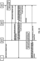
- FIG. 13A illustrates a four-step contention-based random access procedure.
- a base station may transmit a configuration message 1310 to the UE.
- the procedure illustrated in FIG. 13A comprises transmission of four messages: a Msg 1 1311, a Msg 2 1312, a Msg 3 1313, and a Msg 4 1314.
- the Msg 1 1311 may include and/or be referred to as a preamble (or a random access preamble).
- the Msg 2 1312 may include and/or be referred to as a random access response (RAR).
- RAR random access response
- the configuration message 1310 may be transmitted, for example, using one or more RRC messages.
- the one or more RRC messages may indicate one or more random access channel (RACH) parameters to the UE.
- the one or more RACH parameters may comprise at least one of following: general parameters for one or more random access procedures (e.g., RACH-configGeneral); cell-specific parameters (e.g., RACH-ConfigCommon); and/or dedicated parameters (e.g., RACH-configDedicated).
- the base station may broadcast or multicast the one or more RRC messages to one or more UEs.
- the one or more RRC messages may be UE-specific (e.g., dedicated RRC messages transmitted to a UE in an RRC_CONNECTED state and/or in an RRC _INACTIVE state).
- the UE may determine, based on the one or more RACH parameters, a time-frequency resource and/or an uplink transmit power for transmission of the Msg 1 1311 and/or the Msg 3 1313. Based on the one or more RACH parameters, the UE may determine a reception timing and a downlink channel for receiving the Msg 2 1312 and the Msg 4 1314.
- the one or more RACH parameters provided in the configuration message 1310 may indicate one or more Physical RACH (PRACH) occasions available for transmission of the Msg 1 1311.
- the one or more PRACH occasions may be predefined.
- the one or more RACH parameters may indicate one or more available sets of one or more PRACH occasions (e.g., prach-ConfigIndex).
- the one or more RACH parameters may indicate an association between (a) one or more PRACH occasions and (b) one or more reference signals.
- the one or more RACH parameters may indicate an association between (a) one or more preambles and (b) one or more reference signals.
- the one or more reference signals may be SS/PBCH blocks and/or CSI-RSs.
- the one or more RACH parameters may indicate a number of SS/PBCH blocks mapped to a PRACH occasion and/or a number of preambles mapped to a SS/PBCH blocks.
- the UE may determine the preamble based on the one or more RACH parameters provided in the configuration message 1310. For example, the UE may determine the preamble based on a pathloss measurement, an RSRP measurement, and/or a size of the Msg 3 1313.
- the one or more RACH parameters may indicate: a preamble format; a maximum number of preamble transmissions; and/or one or more thresholds for determining one or more preamble groups (e.g., group A and group B).
- a base station may use the one or more RACH parameters to configure the UE with an association between one or more preambles and one or more reference signals (e.g., SSBs and/or CSI-RSs).
- the UE may perform a preamble retransmission if no response is received following a preamble transmission.
- the UE may increase an uplink transmit power for the preamble retransmission.
- the UE may select an initial preamble transmit power based on a pathloss measurement and/or a target received preamble power configured by the network.
- the UE may determine to retransmit a preamble and may ramp up the uplink transmit power.
- the UE may receive one or more RACH parameters (e.g., PREAMBLE_POWER _RAMPING_STEP) indicating a ramping step for the preamble retransmission.
- the ramping step may be an amount of incremental increase in uplink transmit power for a retransmission.
- the UE may ramp up the uplink transmit power if the UE determines a reference signal (e.g., SSB and/or CSI-RS) that is the same as a previous preamble transmission.
- the UE may count a number of preamble transmissions and/or retransmissions (e.g., PREAMBLE_TRANSMISSION_COUNTER).
- the UE may determine that a random access procedure completed unsuccessfully, for example, if the number of preamble transmissions exceeds a threshold configured by the one or more RACH parameters (e.g., preambleTransMax).
- the Msg 2 1312 received by the UE may include an RAR.
- the Msg 2 1312 may include multiple RARs corresponding to multiple UEs.
- the Msg 2 1312 may be received after or in response to the transmitting of the Msg 1 1311.
- the Msg 2 1312 may be scheduled on the DL-SCH and indicated on a PDCCH using a random access RNTI (RA-RNTI).
- RA-RNTI random access RNTI
- the UE may start the time window one or more symbols after a last symbol of the preamble (e.g., at a first PDCCH occasion from an end of a preamble transmission).
- the one or more symbols may be determined based on a numerology.
- the PDCCH may be in a common search space (e.g., a Type1-PDCCH common search space) configured by an RRC message.
- the UE may identify the RAR based on a Radio Network Temporary Identifier (RNTI). RNTIs may be used depending on one or more events initiating the random access procedure.
- the UE may use random access RNTI (RA-RNTI).
- the RA-RNTI may be associated with PRACH occasions in which the UE transmits a preamble.
- Contention resolution (e.g., using the Msg 3 1313 and the Msg 4 1314) may be used to increase the likelihood that the UE does not incorrectly use an identity of another the UE.
- the UE may include a device identifier in the Msg 3 1313 (e.g., a C-RNTI if assigned, a TC-RNTI included in the Msg 2 1312, and/or any other suitable identifier).
- the Msg 4 1314 may be received after or in response to the transmitting of the Msg 3 1313. If a C-RNTI was included in the Msg 3 1313, the base station will address the UE on the PDCCH using the C-RNTI. If the UE's unique C-RNTI is detected on the PDCCH, the random access procedure is determined to be successfully completed. If a TC-RNTI is included in the Msg 3 1313 (e.g., if the UE is in an RRC_IDLE state or not otherwise connected to the base station), Msg 4 1314 will be received using a DL-SCH associated with the TC-RNTI.
- a MAC PDU is successfully decoded and a MAC PDU comprises the UE contention resolution identity MAC CE that matches or otherwise corresponds with the CCCH SDU sent (e.g., transmitted) in Msg 3 1313, the UE may determine that the contention resolution is successful and/or the UE may determine that the random access procedure is successfully completed.
- the UE may be configured with a supplementary uplink (SUL) carrier and a normal uplink (NUL) carrier.
- An initial access (e.g., random access procedure) may be supported in an uplink carrier.
- a base station may configure the UE with two separate RACH configurations: one for an SUL carrier and the other for an NUL carrier.
- the network may indicate which carrier to use (NUL or SUL).
- the UE may determine the SUL carrier, for example, if a measured quality of one or more reference signals is lower than a broadcast threshold.
- Uplink transmissions of the random access procedure (e.g., the Msg 1 1311 and/or the Msg 3 1313) may remain on the selected carrier.
- the UE may switch an uplink carrier during the random access procedure (e.g., between the Msg 1 1311 and the Msg 3 1313) in one or more cases. For example, the UE may determine and/or switch an uplink carrier for the Msg 1 1311 and/or the Msg 3 1313 based on a channel clear assessment (e.g., a listen-before-talk).
- a channel clear assessment e.g., a listen-before-talk.
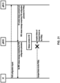
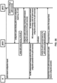
- FIG. 13B illustrates a two-step contention-free random access procedure. Similar to the four-step contention-based random access procedure illustrated in FIG. 13A , a base station may, prior to initiation of the procedure, transmit a configuration message 1320 to the UE.
- the configuration message 1320 may be analogous in some respects to the configuration message 1310.
- the procedure illustrated in FIG. 13B comprises transmission of two messages: a Msg 1 1321 and a Msg 2 1322.
- the Msg 1 1321 and the Msg 2 1322 may be analogous in some respects to the Msg 1 1311 and a Msg 2 1312 illustrated in FIG. 13A , respectively.
- the contention-free random access procedure may not include messages analogous to the Msg 3 1313 and/or the Msg 4 1314.
- the contention-free random access procedure illustrated in FIG. 13B may be initiated for a beam failure recovery, other SI request, SCell addition, and/or handover.
- a base station may indicate or assign to the UE the preamble to be used for the Msg 1 1321.
- the UE may receive, from the base station via PDCCH and/or RRC, an indication of a preamble (e.g., ra-PreambleIndex).
- the UE may start a time window (e.g., ra-ResponseWindow) to monitor a PDCCH for the RAR.
- a time window e.g., ra-ResponseWindow
- the base station may configure the UE with a separate time window and/or a separate PDCCH in a search space indicated by an RRC message (e.g., recoverySearchSpaceId).
- the UE may monitor for a PDCCH transmission addressed to a Cell RNTI (C-RNTI) on the search space.
- C-RNTI Cell RNTI
- the UE may determine that a random access procedure successfully completes after or in response to transmission of Msg 1 1321 and reception of a corresponding Msg 2 1322.
- the UE may determine that a random access procedure successfully completes, for example, if a PDCCH transmission is addressed to a C-RNTI.
- the UE may determine that a random access procedure successfully completes, for example, if the UE receives an RAR comprising a preamble identifier corresponding to a preamble transmitted by the UE and/or the RAR comprises a MAC sub-PDU with the preamble identifier.
- the UE may determine the response as an indication of an acknowledgement for an SI request.
- FIG. 13C illustrates another two-step random access procedure. Similar to the random access procedures illustrated in FIGS. 13A and 13B , a base station may, prior to initiation of the procedure, transmit a configuration message 1330 to the UE.
- the configuration message 1330 may be analogous in some respects to the configuration message 1310 and/or the configuration message 1320.
- the procedure illustrated in FIG. 13C comprises transmission of two messages: a Msg A 1331 and a Msg B 1332.
- Msg A 1331 may be transmitted in an uplink transmission by the UE.
- Msg A 1331 may comprise one or more transmissions of a preamble 1341 and/or one or more transmissions of a transport block 1342.
- the transport block 1342 may comprise contents that are similar and/or equivalent to the contents of the Msg 3 1313 illustrated in FIG. 13A .
- the transport block 1342 may comprise UCI (e.g., an SR, a HARQ ACK/NACK, and/or the like).
- the UE may receive the Msg B 1332 after or in response to transmitting the Msg A 1331.
- the Msg B 1332 may comprise contents that are similar and/or equivalent to the contents of the Msg 2 1312 (e.g., an RAR) illustrated in FIGS. 13A and 13B and/or the Msg 4 1314 illustrated in FIG. 13A .
- the UE may initiate the two-step random access procedure in FIG. 13C for licensed spectrum and/or unlicensed spectrum.
- the UE may determine, based on one or more factors, whether to initiate the two-step random access procedure.
- the one or more factors may be: a radio access technology in use (e.g., LTE, NR, and/or the like); whether the UE has valid TA or not; a cell size; the UE's RRC state; a type of spectrum (e.g., licensed vs. unlicensed); and/or any other suitable factors.
- the UE may determine, based on two-step RACH parameters included in the configuration message 1330, a radio resource and/or an uplink transmit power for the preamble 1341 and/or the transport block 1342 included in the Msg A 1331.
- the RACH parameters may indicate a modulation and coding schemes (MCS), a time-frequency resource, and/or a power control for the preamble 1341 and/or the transport block 1342.
- MCS modulation and coding schemes
- a time-frequency resource for transmission of the preamble 1341 e.g., a PRACH
- a time-frequency resource for transmission of the transport block 1342 e.g., a PUSCH
- the RACH parameters may enable the UE to determine a reception timing and a downlink channel for monitoring for and/or receiving Msg B 1332.
- the transport block 1342 may comprise data (e.g., delay-sensitive data), an identifier of the UE, security information, and/or device information (e.g., an International Mobile Subscriber Identity (IMSI)).
- the base station may transmit the Msg B 1332 as a response to the Msg A 1331.
- the Msg B 1332 may comprise at least one of following: a preamble identifier; a timing advance command; a power control command; an uplink grant (e.g., a radio resource assignment and/or an MCS); a UE identifier for contention resolution; and/or an RNTI (e.g., a C-RNTI or a TC-RNTI).
- RNTI e.g., a C-RNTI or a TC-RNTI
- the UE may determine that the two-step random access procedure is successfully completed if: a preamble identifier in the Msg B 1332 is matched to a preamble transmitted by the UE; and/or the identifier of the UE in Msg B 1332 is matched to the identifier of the UE in the Msg A 1331 (e.g., the transport block 1342).
- a UE and a base station may exchange control signaling.
- the control signaling may be referred to as L1/L2 control signaling and may originate from the PHY layer (e.g., layer 1) and/or the MAC layer (e.g., layer 2).
- the control signaling may comprise downlink control signaling transmitted from the base station to the UE and/or uplink control signaling transmitted from the UE to the base station.
- the downlink control signaling may comprise: a downlink scheduling assignment; an uplink scheduling grant indicating uplink radio resources and/or a transport format; a slot format information; a preemption indication; a power control command; and/or any other suitable signaling.
- the UE may receive the downlink control signaling in a payload transmitted by the base station on a physical downlink control channel (PDCCH).
- the payload transmitted on the PDCCH may be referred to as downlink control information (DCI).
- the PDCCH may be a group common PDCCH (GC-PDCCH) that is common to a group of UEs.
- a base station may attach one or more cyclic redundancy check (CRC) parity bits to a DCI in order to facilitate detection of transmission errors.
- CRC cyclic redundancy check
- the base station may scramble the CRC parity bits with an identifier of the UE (or an identifier of the group of the UEs). Scrambling the CRC parity bits with the identifier may comprise Modulo-2 addition (or an exclusive OR operation) of the identifier value and the CRC parity bits.
- the identifier may comprise a 16-bit value of a radio network temporary identifier (RNTI).
- RNTI radio network temporary identifier
- DCIs may be used for different purposes.
- a purpose may be indicated by the type of RNTI used to scramble the CRC parity bits.
- a DCI having CRC parity bits scrambled with a paging RNTI may indicate paging information and/or a system information change notification.
- the P-RNTI may be predefined as "FFFE” in hexadecimal.
- a DCI having CRC parity bits scrambled with a system information RNTI (SI-RNTI) may indicate a broadcast transmission of the system information.
- SI-RNTI may be predefined as "FFFF" in hexadecimal.
- a DCI having CRC parity bits scrambled with a random access RNTI may indicate a random access response (RAR).
- a DCI having CRC parity bits scrambled with a cell RNTI may indicate a dynamically scheduled unicast transmission and/or a triggering of PDCCH-ordered random access.
- a DCI having CRC parity bits scrambled with a temporary cell RNTI may indicate a contention resolution (e.g., a Msg 3 analogous to the Msg 3 1313 illustrated in FIG. 13A ).
- RNTIs configured to the UE by a base station may comprise a Configured Scheduling RNTI (CS-RNTI), a Transmit Power Control-PUCCH RNTI (TPC-PUCCH-RNTI), a Transmit Power Control-PUSCH RNTI (TPC-PUSCH-RNTI), a Transmit Power Control-SRS RNTI (TPC-SRS-RNTI), an Interruption RNTI (INT-RNTI), a Slot Format Indication RNTI (SFI-RNTI), a Semi-Persistent CSI RNTI (SP-CSI-RNTI), a Modulation and Coding Scheme Cell RNTI (MCS-C-RNTI), and/or the like.
- CS-RNTI Configured Scheduling RNTI
- TPC-PUCCH-RNTI Transmit Power Control-PUSCH RNTI
- TPC-SRS-RNTI Transmit Power Control-SRS RNTI
- INT-RNTI Interruption RNTI
- the base station may transmit the DCIs with one or more DCI formats.
- DCI format 0_0 may be used for scheduling of PUSCH in a cell.
- DCI format 0_0 may be a fallback DCI format (e.g., with compact DCI payloads).
- DCI format 0_1 may be used for scheduling of PUSCH in a cell (e.g., with more DCI payloads than DCI format 0_0).
- DCI format 1_0 may be used for scheduling of PDSCH in a cell.
- DCI format 1_0 may be a fallback DCI format (e.g., with compact DCI payloads).
- DCI format 1_1 may be used for scheduling of PDSCH in a cell (e.g., with more DCI payloads than DCI format 1_0).
- DCI format 2_0 may be used for providing a slot format indication to a group of UEs.
- DCI format 2_1 may be used for notifying a group of UEs of a physical resource block and/or OFDM symbol where the UE may assume no transmission is intended to the UE.
- DCI format 2_2 may be used for transmission of a transmit power control (TPC) command for PUCCH or PUSCH.
- DCI format 2_3 may be used for transmission of a group of TPC commands for SRS transmissions by one or more UEs.
- DCI format(s) for new functions may be defined in future releases.
- DCI formats may have different DCI sizes, or may share the same DCI size.
- the base station may process the DCI with channel coding (e.g., polar coding), rate matching, scrambling and/or QPSK modulation.
- channel coding e.g., polar coding
- a base station may map the coded and modulated DCI on resource elements used and/or configured for a PDCCH.
- the base station may transmit the DCI via a PDCCH occupying a number of contiguous control channel elements (CCEs).
- the number of the contiguous CCEs (referred to as aggregation level) may be 1, 2, 4, 8, 16, and/or any other suitable number.
- a CCE may comprise a number (e.g., 6) of resource-element groups (REGs).
- REG may comprise a resource block in an OFDM symbol.
- the mapping of the coded and modulated DCI on the resource elements may be based on mapping of CCEs and REGs (e.g., CCE-to-REG mapping).
- FIG. 14A illustrates an example of CORESET configurations for a bandwidth part.
- the base station may transmit a DCI via a PDCCH on one or more control resource sets (CORESETs).
- a CORESET may comprise a time-frequency resource in which the UE tries to decode a DCI using one or more search spaces.
- the base station may configure a CORESET in the time-frequency domain.
- a first CORESET 1401 and a second CORESET 1402 occur at the first symbol in a slot.
- the first CORESET 1401 overlaps with the second CORESET 1402 in the frequency domain.
- a third CORESET 1403 occurs at a third symbol in the slot.
- a fourth CORESET 1404 occurs at the seventh symbol in the slot.
- CORESETs may have a different number of resource blocks in frequency domain.
- FIG. 14B illustrates an example of a CCE-to-REG mapping for DCI transmission on a CORESET and PDCCH processing.
- the CCE-to-REG mapping may be an interleaved mapping (e.g., for the purpose of providing frequency diversity) or a non-interleaved mapping (e.g., for the purposes of facilitating interference coordination and/or frequencyselective transmission of control channels).
- the base station may perform different or same CCE-to-REG mapping on different CORESETs.
- a CORESET may be associated with a CCE-to-REG mapping by RRC configuration.
- a CORESET may be configured with an antenna port quasi co-location (QCL) parameter.
- the antenna port QCL parameter may indicate QCL information of a demodulation reference signal (DMRS) for PDCCH reception in the CORESET.
- DMRS demodulation reference signal
- the base station may transmit, to the UE, RRC messages comprising configuration parameters of one or more CORESETs and one or more search space sets.
- the configuration parameters may indicate an association between a search space set and a CORESET.
- a search space set may comprise a set of PDCCH candidates formed by CCEs at a given aggregation level.
- the configuration parameters may indicate: a number of PDCCH candidates to be monitored per aggregation level; a PDCCH monitoring periodicity and a PDCCH monitoring pattern; one or more DCI formats to be monitored by the UE; and/or whether a search space set is a common search space set or a UE-specific search space set.
- a set of CCEs in the common search space set may be predefined and known to the UE.
- a set of CCEs in the UE-specific search space set may be configured based on the UE's identity (e.g., C-RNTI).
- the UE may determine a time-frequency resource for a CORESET based on RRC messages.
- the UE may determine a CCE-to-REG mapping (e.g., interleaved or non-interleaved, and/or mapping parameters) for the CORESET based on configuration parameters of the CORESET.
- the UE may determine a number (e.g., at most 10) of search space sets configured on the CORESET based on the RRC messages.
- the UE may monitor a set of PDCCH candidates according to configuration parameters of a search space set.
- the UE may monitor a set of PDCCH candidates in one or more CORESETs for detecting one or more DCIs.
- the UE may transmit an SR indicating that uplink data is available for transmission to the base station.
- the UE may transmit a UCI (e.g., HARQ acknowledgements (HARQ-ACK), CSI report, SR, and the like) via a physical uplink control channel (PUCCH) or a physical uplink shared channel (PUSCH).
- HARQ-ACK HARQ acknowledgements
- CSI report CSI report
- SR SR
- the UE may transmit the uplink control signaling via a PUCCH using one of several PUCCH formats.
- PUCCH format 0 may have a length of one or two OFDM symbols and may include two or fewer bits.
- the UE may transmit UCI in a PUCCH resource using PUCCH format 0 if the transmission is over one or two symbols and the number of HARQ-ACK information bits with positive or negative SR (HARQ-ACK/SR bits) is one or two.
- PUCCH format 1 may occupy a number between four and fourteen OFDM symbols and may include two or fewer bits.
- the UE may use PUCCH format 1 if the transmission is four or more symbols and the number of HARQ-ACK/SR bits is one or two.
- PUCCH format 2 may occupy one or two OFDM symbols and may include more than two bits.
- the UE may use PUCCH format 2 if the transmission is over one or two symbols and the number of UCI bits is two or more.
- PUCCH format 3 may occupy a number between four and fourteen OFDM symbols and may include more than two bits.
- the UE may use PUCCH format 3 if the transmission is four or more symbols, the number of UCI bits is two or more and PUCCH resource does not include an orthogonal cover code.
- PUCCH format 4 may occupy a number between four and fourteen OFDM symbols and may include more than two bits. The UE may use PUCCH format 4 if the transmission is four or more symbols, the number of UCI bits is two or more and the PUCCH resource includes an orthogonal cover code.
- the UE may select a third PUCCH resource set having a PUCCH resource set index equal to "2". If the total bit length of UCI information bits is greater than the second configured value and less than or equal to a third value (e.g., 1406), the UE may select a fourth PUCCH resource set having a PUCCH resource set index equal to "3".
- a third value e.g. 1406
- FIG. 15 illustrates an example of a wireless device 1502 in communication with a base station 1504 in accordance with embodiments of the present disclosure.
- the wireless device 1502 and base station 1504 may be part of a mobile communication network, such as the mobile communication network 100 illustrated in FIG. 1A , the mobile communication network 150 illustrated in FIG. 1B , or any other communication network. Only one wireless device 1502 and one base station 1504 are illustrated in FIG. 15 , but it will be understood that a mobile communication network may include more than one UE and/or more than one base station, with the same or similar configuration as those shown in FIG. 15 .
- the data to be sent to the wireless device 1502 may be provided to a transmission processing system 1510 of base station 1504.
- the data to be sent to base station 1504 may be provided to a transmission processing system 1520 of the wireless device 1502.
- the transmission processing system 1510 and the transmission processing system 1520 may implement layer 1 OSI functionality.
- Layer 1 may include a PHY layer with respect to FIG. 2A, FIG. 2B , FIG. 3 , and FIG. 4A .
- a reception processing system 1512 may receive the uplink transmission from the wireless device 1502.
- a reception processing system 1522 may receive the downlink transmission from base station 1504.
- the reception processing system 1512 and the reception processing system 1522 may implement layer 1 OSI functionality.
- Layer 1 may include a PHY layer with respect to FIG. 2A, FIG. 2B , FIG. 3 , and FIG. 4A .
- the PHY layer may perform, for example, error detection, forward error correction decoding, deinterleaving, demapping of transport channels to physical channels, demodulation of physical channels, MIMO or multi-antenna processing, and/or the like.
- the processing system 1508 and/or the processing system 1518 may comprise one or more controllers and/or one or more processors.
- the one or more controllers and/or one or more processors may comprise, for example, a general-purpose processor, a digital signal processor (DSP), a microcontroller, an application specific integrated circuit (ASIC), a field programmable gate array (FPGA) and/or other programmable logic device, discrete gate and/or transistor logic, discrete hardware components, an on-board unit, or any combination thereof.
- DSP digital signal processor
- ASIC application specific integrated circuit
- FPGA field programmable gate array
- FIG. 16A illustrates an example structure for uplink transmission.
- a baseband signal representing a physical uplink shared channel may perform one or more functions.
- the one or more functions may comprise at least one of: scrambling; modulation of scrambled bits to generate complex-valued symbols; mapping of the complex-valued modulation symbols onto one or several transmission layers; transform precoding to generate complex-valued symbols; precoding of the complex-valued symbols; mapping of precoded complex-valued symbols to resource elements; generation of complex-valued time-domain Single Carrier-Frequency Division Multiple Access (SC-FDMA) or CP-OFDM signal for an antenna port; and/or the like.
- SC-FDMA Single Carrier-Frequency Division Multiple Access
- CP-OFDM signal for an antenna port; and/or the like.
- FIG. 16A illustrates an example structure for uplink transmission.
- These functions are illustrated as examples and it is anticipated that other mechanisms may be implemented in various embodiments.
- the (ng-)eNB or gNB may decide to provide an uplink resource to the UE or to release an existing PUR resource.
- the (ng-)eNB or gNB may include parameters of the PUR configuration or an uplink resource release indication in the RRC Connection Release message.
- the (ng-)eNB or gNB may provide an uplink resource configuration ID with the PUR configuration. If available, the UE may include the PUR configuration ID in RRC Connection Setup/Resume Complete message when establishing/resuming RRC connection(s) not using the PUR resource.
- the PUR configuration may be released at the UE and/or (ng-)eNB/gNB, when the UE accesses in another cell, when PUR is no longer enabled in the cell, and/or when the PUR resource has not been used for a configured number of consecutive occasions.
- a UE and PUR configuration may be linked according to configured PUR resources.
- a UE may determine that the PUR resource can be used (e.g., PUR enabled in the cell, valid Time Alignment, etc.). The UE may transmit over the PUR resource. If the uplink data are too large to be included in RRC Early Data Request, the UE may use the PUR resource to transmit RRC Connection Request. The procedure may fall back to an RRC Connection establishment procedure and/or a new C-RNTI may be assigned. The (ng-)eNB or gNB may request the UE to abort the transmission using PUR by sending a Layer 1 fallback indication.
- the PUR resource e.g., PUR enabled in the cell, valid Time Alignment, etc.
- RRC Connection Setup message may be sent to fall back to the RRC Connection establishment procedure and/or a new C-RNTI may be assigned.
- the (ng-)eNB or gNB may discard a zero-length NAS PDU received in RRC Connection Setup Complete message.
- the UE may consider the UL data transmission not successful.
- the keys may be derived using the Next Hop Chaining Count provided in the RRC Connection Release message of the previous RRC connection.
- the RRC Connection Release message may be integrity protected and/or ciphered using the newly derived keys.
- the UE may not transition to RRC CONNECTED.
- the UE may transmit data using PUR for the User Plane CIoT EPS optimization and for the User Plane CIoT 5GS optimization.
- the UE may validate the PUR resource according to the configured criteria (e.g., TA validation, RSRP validation, etc.). In an example, the UE may transmit over the PUR resource instead of a resource allocated in the random access response.
- the UE may send an RRC Connection Resume Request to the eNB or gNB, including its Resume ID, the establishment cause, and/or an authentication token.
- the UE may resume SRBs and DRBs.
- the UE may derive new security keys using the NextHopChainingCount provided in the RRC Connection Release message of the previous RRC connection and/or may re-establish the AS security.
- the UE may indicate AS Release Assistance Information. If the user data are too large to be included in the transmission using PUR, the UE may use PUR to transmit RRC Connection Resume Request and a segment of the user data. The procedure may be fall back to the RRC Connection Resume procedure. A new C-RNTI may be assigned.
- the (ng-)eNB or gNB may request the UE to abort the transmission using PUR by sending a Layer 1 fallback indication.
- the eNB or gNB may initiate the S1-AP Context Resume procedure to resume the S1 connection and re-activate the S1-U bearers.
- the MME may request the S-GW to re-activate the S1-U bearers for the UE.
- the MME may confirm the UE context resumption to the eNB or gNB.
- the uplink data may be delivered to the S-GW. If downlink data are available, the S-GW may send the downlink data to the eNB or gNB. If no further data are expected, the eNB or gNB may initiate the suspension of the S1 connection and/or the deactivation of the S1-U bearers.
- the uplink data may be delivered to the UPF.
- the ng-eNB or gNB may send a NG-AP Context Resume Request message to the AMF to resume the connection. If the UE included AS Release Assistance information indicating No further UL/DL higher layer PDU, ng-eNB or gNB may request for immediate transition to RRC_IDLE with Suspend and/or RRC_INACTIVE. In an example, If the AMF does not receive a request for immediate transition to IDLE with Suspend or the AMF is aware of downlink data or signaling pending, the AMF may request the SMF to resume the PDU session. The AMF may send a NG-AP Context Resume Response to the ng-eNB or gNB.
- the AMF may include a Suspend indication and/or may keep the UE in CM-IDLE with Suspend.
- the AMF may wait for the DL data to arrive.
- the ng-eNB or gNB may initiate the NG-AP UE Context Suspend procedure to inform the AMF that the RRC connection is being suspended.
- the AMF may request the SMF to suspend the PDU session.
- the SMF may request the UPF to release the tunnel information for the UE.
- the eNB or gNB may send the RRCConnectionRelease message to keep the UE in RRC_IDLE.
- the message includes the releaseCause set to rrc-Suspend, the resumeID, the I-RNTI, the NextHopChainingCount and drb-ContinueROHC which are stored by the UE. If downlink data were received, the downlink data may be sent ciphered on DTCH multiplexed with the RRCConnectionRelease message on DCCH.
- the RRC connection release message may include the Time Advance Command.
- RRC Connection Resume message may be sent to fall back to the RRC Connection resume procedure.
- the RRC Connection Resume message may be integrity protected and/or ciphered with the keys.
- the UE may ignore the Next Hop Chaining Count included in the RRC Connection Resume message.
- a new C-RNTI may be assigned.
- Downlink data may be transmitted on DTCH multiplexed with the RRC Connection Resume message.
- An RRC Connection Setup may be also be sent to fall back to the RRC Connection establishment procedure. If neither RRC Connection Release nor, in case of fallback, RRC Connection Resume is received in response to RRC Connection Resume Request using PUR, the UE may consider the UL data transmission not successful.
- the PUR response window may start at the subframe/slot/symbol that contains the end of the corresponding PUSCH transmission plus 4 subframes/slot/symbol.
- the PUR response window may have the length pur-ResponseWindowSize. While pur-ResponseWindowTimer is running, the MAC entity may restart pur-ResponseWindowTimer at the last subframe/slot/symbol of a PUSCH transmission corresponding to the retransmission indicated by the UL grant plus 4 subframes/slots/symbols if the PDCCH transmission is addressed to the PUR-RNTI and contains an UL grant for a retransmission.
- the MAC entity may stop pur-ResponseWindowTimer. If L1 ACK for transmission using PUR is received from lower layers and/or the MAC PDU contains only Timing Advance Command MAC control element, the MAC entity may indicate to upper layers the transmission using PUR was successful and/or may discard the PUR-RNTI. If repetition adjustment for transmission using PUR is received from lower layers, the MAC entity may indicate the value of the repetition adjustment to upper layers.
- the MAC entity may stop pur-ResponseWindowTimer and/or may indicate to upper layers that PUR fallback indication is received and/or may discard the PUR-RNTI. If repetition adjustment for transmission using PUR is received from lower layers, the MAC entity may indicate the value of the repetition adjustment to upper layers. If the pur-ResponseWindowTimer expires, the MAC entity may indicate to upper layers the transmission using PUR has failed and/or discard the PUR-RNTI.
- the MAC entity may maintain timer pur-TimeAlignmentTimer by upper layers (e.g., RRC layer).
- the MAC entity may start pur-TimeAlignmentTimer when pur-TimeAlignmentTimer configuration is received from upper layers.
- the MAC entity may stop the pur-TimeAlignmentTimer when pur-TimeAlignmentTimer is released by upper layers.
- the MAC entity may apply the Timing Advance Command or the timing advance adjustment and/or may start/restart the pur-TimeAlignmentTimer when a Timing Advance Command MAC control element is received or PDCCH indicates timing advance adjustment.
- MAC entity may indicate whether pur-TimeAlignmentTimer is running.
- a UE may consider the timing alignment value for transmission using PUR to be valid when pur-TimeAlignmentTimer is running as confirmed by lower layers if pur-TimeAlignmentTimer is configured. In an example, a UE may consider the timing alignment value for transmission using PUR to be valid when, since the last TA validation, the serving cell RSRP has not increased by more than increaseThresh and/or the serving cell RSRP has not decreased by more than decreaseThresh if pur-RSRP-ChangeThreshold (pur-NRSRP-ChangeThreshold in NB-IoT) is configured.
- pur-RSRP-ChangeThreshold pur-NRSRP-ChangeThreshold in NB-IoT
- a UE configured with uplink resource parameters may consider that the first uplink grant occasion occurs at the H-SFN/SFN/subframe given by H-SFN and/or SFN and subframe indicated by startSFN and startSubframe.
- H-SFN may be determined based on (H-SFNRef + offset) mod 1024 occurring after FLOOR (offset/1024) H-SFN cycles. The offset may be given by periodicityAndOffset.
- H-SFNRef may correspond to the last subframe of the first transmission of RRC Connection Release message containing the uplink resource parameters, taking into account hsfn-LSB-Info.
- H-SFN cycle may correspond to a duration of 1024 H-SFNs.
- the UE may release the uplink resource parameters, may discard previously stored uplink resource parameters, and/or may indicate to lower layers that pur-TimeAlignmentTimer is released (e.g., if pur-TimeAlignmentTimer is configured).
- a UE may consider that subsequent PUR occasions occur periodically after an occurrence of the first PUR occasion at the SFN/subframe indicated by startSubframe and startSFN and periodicity given by periodicityAndOffset.
- a pur-ImplicitReleaseAfter is configured, for a PUR occasion occurring while the UE is in RRC_IDLE or RRC_INACTIVE, if transmission using PUR is not initiated or if PUR failure indication is received from lower layers, the UE may consider the PUR occasion as skipped.
- the UE may release uplink resource parameters, may discard previously stored uplink resource parameters, and/or may indicate to lower layers that pur-TimeAlignmentTimer is released if pur-TimeAlignmentTimer is configured.
- a small data transmission (SDT) procedure may comprise exchange of user data between a wireless device and a base station while the wireless device is in a non-connected state (e.g., a radio resource control (RRC) non-connected state) (e.g., an idle state, inactive state, etc.).
- the amount of data exchanged in an SDT transmission of the SDT procedure may be smaller than a threshold amount of data.
- the SDT procedure may comprise one SDT transmission of a small amount of data and/or a sequence of SDT transmissions.
- the wireless device and/or base station may transmit and/or receive data via the user plane (UP) or the control plane (CP) while the wireless device remains in the non-connected state (e.g., idle, inactive, etc.).
- the wireless device may transmit and/or receive data without completing a connection setup or resume procedure (and without control plane signaling associated with setup and/or resumption).
- the data may comprise user data and a signal.
- a wireless device may require a grant to transmit data (e.g., uplink data) associated with an SDT procedure.
- the wireless device may receive the grant from/via a base station.
- the grant may be an uplink grant for one or more uplink resources, and the wireless device may use the one or more uplink resources to transmit data (e.g., uplink data).
- the grant may be a dynamic uplink grant or a configured uplink grant of the one or more uplink resources.
- the dynamic uplink grant may indicate one or more specific uplink resources to be used for uplink transmission at a specific time.
- the configured uplink grant may indicate resources which are repeating, intermittent, and/or periodic.
- a configured uplink grant configuration may indicate a periodicity of the configured uplink grant and one or more uplink resources of the configured uplink grant configuration may be used and re-used at periodic intervals.
- a configured uplink grant may be configured/activated, and resources associated with a configured uplink grant configuration of the configured uplink grant may be used until the configured uplink grant is released/deactivated.
- a dynamic uplink grant may indicate resources at time k, whereas a configured uplink grant may grant resources at times k+nT, where T is a period of the configured uplink grant and n is an integer [0, 1, 2, ...].
- the wireless device may obtain the uplink grant via a physical or MAC signal (e.g., DCI or an random access (RA) response) indicating the uplink grant.
- a physical or MAC signal e.g., DCI or an random access (RA) response
- RA random access
- the wireless device may send an RA preamble requesting one or more uplink resources.
- the wireless device may receive an uplink grant indicating one or more uplink resources for transmitting the small data.
- the wireless device may obtain the uplink grant based on a configured uplink grant.
- the configured uplink grant may be associated with a configured uplink grant configuration (e.g., preconfigured uplink resource (PUR) configuration).
- the wireless device may receive the configured uplink grant configuration via an RRC message (e.g., an RRC release message).
- the configured uplink grant configuration may indicate a grant of one or more uplink resources, and the wireless device may use and/or re-use the one or more uplink resources (e.g., pre-configured uplink resources) for transmitting the small data.
- a UE may send configured uplink grant configuration request message to a base station where the configured uplink grant configuration request message may comprise at least one of: requested number of configured uplink grant occasions where the number may be one or infinite; requested periodicity of configured uplink grant; requested transport block size (TBS) for configured uplink grant; and/or requested time offset for a first configured uplink grant occasion.
- PUR preconfigured uplink resource
- the base station may send configured uplink grant configuration (parameters) comprising the preconfigured uplink resource to the UE. For example, in response to the configured uplink grant configuration request message, the base station may send configured uplink grant configuration parameters comprising the preconfigured uplink resource to the UE. For example, the base station may send an RRC release message comprising the configured uplink grant configuration parameters.
- a base station may configure uplink resources for a wireless device.
- the wireless device may use the configured resources (e.g., preconfigured uplink resource, PUR) for uplink transmissions when the wireless device is in an RRC idle state.
- PUR preconfigured uplink resource
- a base station distributed unit may release contexts of a wireless device when the wireless device transitions to an RRC inactive state and/or an RRC idle state.
- the base station distributed unit may not monitor the configured resource after releasing the contexts of the wireless device when the wireless device is in the RRC inactive state and/or the RRC idle state. As shown in FIG.
- the base station distributed unit may not successfully receive the transmitted transport blocks due to not monitoring the configured resource and/or releasing configuration parameters (e.g., PUR-RNTI) of the configured resources.
- PUR-RNTI configuration parameters
- An implementation of existing technologies may make a wireless device in an RRC inactive state or an RRC idle state unable to communicate with a base station using configured resources (e.g., PUR). The existing technologies may decrease communication reliability of wireless devices.
- Example embodiments may support a wireless device in an RRC inactive state or an RRC idle state to communicate with a base station that is split into a base station central unit and one or more base station distributed units.
- Example embodiments may support a base station distributed unit to determine configuration parameters of configured resources for a wireless device.
- the wireless device may be in an RRC non-connected state (e.g., RRC inactive state or an RRC idle state).
- the base station distributed unit may send the configuration parameters to a base station central unit. Based on the configuration parameters of the configured resources, the base station distributed unit may receive, from the wireless device in the RRC non-connected state, one or more transport blocks via the configured resources.
- Example embodiments may increase communication reliability of wireless devices in an RRC inactive state or an RRC idle state.
- a wireless device may communicate with a base station comprising a base station central unit (gNB-CU) and a base station distributed unit (gNB-DU).
- the wireless device may directly communicate with the base station distributed unit via wireless channels of one or more cells comprising a cell (Cell1).
- the wireless device may communicate with the base station central unit via the base station distributed unit.
- the base station distributed unit and the base station central unit may be connected to each other via an F1 interface comprising an F1 control plane interface (F1-C) and/or an F1 user plane interface (F1-U).
- the base station central unit may comprise a base station central unit control plane (gNB-CU-CP) and/or a base station central unit user plane (gNB-CU-UP).
- the base station distributed unit may communicate with the base station central unit control plane via the F1 control plane interface.
- the base station distributed unit may communicate with the base station central unit user plane via the F1 user plane interface.
- the base station central unit control plane may communicate with the base station central unit user plane via an E1 interface.
- the base station may comprise a plurality of base station distributed units comprising the base station distributed unit and a second base station distributed unit.
- the base station central unit may communicate with the plurality of base station distributed units via a plurality of F1 interfaces.
- the wireless device may communicate with the plurality of base station distributed units.
- the wireless device may communicate with the base station central unit via the plurality of base station distributed units.
- the base station distributed unit may receive, from the base station central unit, a configuration request message requesting at least one preconfigured uplink resource (PUR).
- the base station distributed unit may send, to the base station central unit, a configuration message comprising configuration parameters of the at least one PUR.
- the base station distributed unit may receive, from the wireless device in an RRC idle state or an RRC inactive state, one or more transport blocks via the at least one PUR.
- the base station distributed unit may receive, from the base station central unit (gNB-CU), a configuration request message (e.g., PUR configuration request) requesting at least one uplink resource.
- the uplink resource may be, for example, a PUR, a periodic resource, a configured uplink grant resource, or the like.
- the base station central unit may receive, from the wireless device, a request message requesting the at least one uplink resource.
- the receiving the request message may comprise receiving the request message via at least one of: the base station distributed unit or the second base station distributed unit.
- the base station central unit may send, to the base station distributed unit, the configuration request message requesting the at least one PUR based on the request message.
- the base station distributed unit may determine configuration parameters (e.g., PUR configuration parameters for PUR(s), configured uplink grant configuration parameters for configured uplink grant(s)) of the at least one uplink resource.
- the base station distributed unit may send, to the base station central unit, a configuration message comprising the configuration parameters of the at least one uplink resource.
- the base station central unit may send, to the wireless device, one or more radio resource control (RRC) messages.
- the one or more RRC messages may indicate to transition to an RRC idle state or an RRC inactive state.
- the one or more RRC messages may indicate to stay/keep in an RRC idle state or an RRC inactive state.
- the one or more RRC messages may comprise the configuration parameters (e.g., the PUR configuration parameters for the PUR(s), configured uplink grant configuration parameters for configured uplink grant(s)) of the at least one uplink resource.
- the sending the one or more RRC message may comprise sending the one or more RRC message via at least one of: the base station distributed unit or the second base station distributed unit.
- the base station distributed unit may send, to the wireless device (UE), the one or more RRC messages (e.g., the RRC release/suspend message) that the base station distributed unit received from the base station central unit.
- the base station distributed unit may receive, from the wireless device in the RRC idle state or the RRC inactive state, one or more transport blocks via the at least one uplink resource based on the configuration parameters of the at least one uplink resource.
- the receiving the request message by the base station central unit may comprise receiving the request message via at least one of: the base station distributed unit or the second base station distributed unit as shown in FIG. 24 .
- the base station distributed unit and/or the second base station distributed unit may receive, from the wireless device, the request message requesting the at least one uplink resource.
- the base station distributed unit and/or the second base station distributed unit may send/forward, to the base station central unit, the request message (e.g., via the F1 interface).
- the base station distributed unit and/or the second base station distributed unit may send/forward, to the base station central unit, the request message via at least one of: an initial uplink RRC message transfer message, an uplink RRC message transfer message, a UE context setup response message, a UE context release request message, a UE context modification response message, a UE context modification required message, and/or the like.
- the request for the at least one uplink resource may be for a service associated with a packet flow comprising at least one of: a bearer, a logical channel, a QoS flow, a PDU session, and/or the like.
- the request message may comprise an identifier of the packet flow.
- the service may be for the wireless device.
- the service may comprise at least one of: sensing temperature/humidity, monitoring emergency situation/accident, monitoring visual signals, etc.
- the request message may comprise, for the at least one uplink resource, at least one of: a requested number of occasions (e.g., requestedNumOccasions; 1 or infinite), a requested periodicity (e.g., requestedPeriodicityAndOffset, requestedPeriodicity), a requested offset (e.g., requestedPeriodicityAndOffset, requestedTimeOffset), a requested transport block size (e.g., requestedTBS), an indication of RRC acknowledgement preference (e.g., rrc-ACK; true), and/or the like.
- a requested number of occasions e.g., requestedNumOccasions; 1 or infinite
- a requested periodicity e.g., requestedPeriodicityAndOffset, requestedPeriodicity
- a requested offset e.g., requestedPeriodicityAndOffset, requestedTimeOffset
- a requested transport block size e.g., requestedTBS
- an indication of RRC acknowledgement preference e.g.
- the requestedNumOccasions may indicate a requested number of uplink resource grant occasions (e.g., value one corresponds to one occasion and value infinite corresponds to infinite occasions).
- the requestedPeriodicityAndOffset may indicate a requested periodicity for uplink resource occasions and/or time offset until the first uplink resource occasion.
- the requestedTBS may indicate a requested TBS (transport block size) for the at least one uplink resource (e.g., b328 corresponds to 328 bits, b344 corresponds to 344 bits and so on; a maximum requested TBS may be limited to an UL TBS size supported by the UE).
- the rrc-ACK may indicate that an RRC response message is preferred by the wireless device for acknowledging a reception of a transmission using the at least one uplink resource.
- the base station central unit may determine to configure the at least one uplink resource for the wireless device. In an example, based on the request message from the wireless device, the base station central unit may determine to request the base station distributed unit to configure the at least one uplink resource.
- the base station central unit may send, to the base station distributed unit, the configuration request message requesting the at least one uplink resource.
- the base station distributed unit may receive, from the base station central unit, the configuration request message requesting the at least one uplink resource.
- the at least one uplink resource may comprise at least one of at least one preconfigured resource, at least one periodic resource, and or at least one configured resource that may be used by a wireless device in an RRC inactive state and/or in an RRC idle state.
- the configuration request message may be based on the request message.
- the configuration request message may comprise the request message from the wireless device.
- the configuration request message may comprise one or more elements of the request message from the wireless device.
- the configuration request message may be for configurations associated with the wireless device (e.g., UE specific configurations), as shown in FIG. 25 .
- the configuration request message may be for configurations associated with the base station distributed unit, a cell of the base station distributed unit, and/or the base station central unit (e.g., gNB-DU specific configurations, cell specific configurations, and/or gNB-CU specific configurations), as shown in FIG. 26 .
- the configuration request message may be at least one of: a user equipment context update message (e.g., UE specific configurations) for the wireless device and/or a base station central unit configuration update message (e.g., gNB-DU specific configurations, cell specific configurations, and/or gNB-CU specific configurations).
- the configuration request message may comprise at least one of: a UE context setup request message, a UE context release command message, a UE context modification request message, a UE context modification confirm message, and/or the like.
- the configuration request message may comprise a wireless device identifier of the wireless device (e.g., if the at least one uplink resource is UE specific configurations).
- the configuration request message may indicate a cell at which the at least one uplink resource is configured.
- the configuration request message may comprise a cell identifier of the cell at which the at least one uplink resource is configured.
- the cell may be at least one of: a primary cell of the wireless device, a secondary cell of the wireless device, a primary secondary cell of the wireless device, and/or an access cell that the wireless device used for a random access.
- the configuration request message may indicate at least one of: one or more beams (e.g., SSB, CSI-RS, etc.) of the cell associated with the at least one uplink resource and/or one or more bandwidth part of the cell associated with the at least one uplink resource.
- the configuration request message may comprise one or more beam indexes indicating the one or more beams of the cell where the at least one uplink resource is configured.
- the configuration request message may comprise one or more bandwidth part indexes indicating the one or more bandwidth part of the cell where the at least one uplink resource is configured.
- the base station distributed unit may determine, based on the configuration request message requesting the at least one uplink resource, the configuration parameters (e.g., periodic uplink resource parameters, PUR-Config, CG-Config, etc.) of the at least one uplink resource.
- FIG. 27 and/or FIG. 28 show examples of the configuration parameters of the at least one uplink resource.
- the base station distributed unit may determine the configuration parameters based on the request message (e.g., the PUR request message) that the base station central unit received from the wireless device.
- the configuration parameters for the at least one uplink resource may comprise at least one of: a periodicity, an offset, a size, an RNTI (e.g., PUR RNTI), and/or the like.
- the configuration parameters may comprise at least one of: an uplink resource configuration identifier (e.g., pur-ConfigID), an uplink resource implicit release after indication (e.g., pur-ImplicitReleaseAfter), uplink resource start time parameters (e.g., pur-StartTimeParameters comprising periodicity AndOffset, startSFN, startSubFrame, hsfn-LSB-Info, etc.), an uplink resource number of occasions (e.g., pur-NumOccasions), an uplink resource RNTI (e.g., pur-RNTI), an uplink resource time alignment timer (e.g., pur-TimeAlignmentTimer), an uplink resource RSRP change threshold (e.g., pur-RSRP-ChangeThre
- the hsfn-LSB-Info may indicate an LSB of an H-SFN corresponding to the last subframe of the first transmission of RRC Connection Release message containing uplink resource parameters (e.g., periodic uplink resource parameters, pur-Config, cg-Config, etc.).
- the pur-GrantInfo may indicate UL grant for transmission using the at least one uplink resource.
- a field set to ce-ModeA may indicate that an uplink resource grant is for CE Mode A.
- a field set to ce-ModeB may indicate that an uplink resource grant is for CE Mode B.
- numRUs may indicate DCI field for PUSCH number of resource units.
- prbAllocationInfo may indicate DCI field for PUSCH resource block assignment.
- mcs may indicate DCI field for PUSCH modulation and/or coding scheme.
- numRepetitions may indicate DCI field for PUSCH repetition number.
- numRUs set to '00' may indicate use of full-PRB resource allocation, otherwise sub-PRB resource allocation.
- subPRB-Allocation may indicate whether sub-PRB resource allocation is used.
- the pur-NumOccasions may indicate a number of uplink resource occasions (e.g., value one corresponds to 1 uplink resource occasion, and value infinite corresponds to an infinite number of uplink resource occasions).
- the pur-PDSCH-FreqHopping may indicate frequency hopping activation/deactivation for PDSCH.
- the pur-PeriodicityAndOffset may indicate a periodicity for uplink resource occasions and/or time offset until the first uplink resource occasion.
- the pur-PUSCH-FreqHopping may indicate frequency hopping activation/deactivation for PUSCH.
- the pur-ResponseWindowTimer may indicate uplink resource MPDCCH search space window duration (e.g., value in subframes; value sf240 corresponds to 240 subframes, value sf480 corresponds to 480 subframes and so on).
- the pur-RSRP-ChangeThreshold (e.g., comprising decreaseThresh and/or increase Thresh) may indicate a threshold(s) of change in serving cell RSRP in dB for TA validation (e.g., value dB4 corresponds to 4 dB, value dB6 corresponds to 6 dB and so on).
- a threshold(s) of change in serving cell RSRP in dB for TA validation e.g., value dB4 corresponds to 4 dB, value dB6 corresponds to 6 dB and so on.
- the base station distributed unit may monitor whether the pur-TimeAlignmentTimer is expired and/or whether a timing advance value that the wireless device maintains/keeps is valid to determine whether the at least one uplink resource is valid.
- the uplink resource MPDCCH configuration parameters (e.g., pur-MPDCCH-Config) of the configuration parameters may comprise at least one of: an MPDCCH frequency hopping parameter (e.g., mpdcch-FreqHopping), an MPDCCH narrowband parameter (e.g., mpdcch-Narrowband), an MPDCCH PRB pairs configuration (e.g., mpdcch-PRB-PairsConfig comprising numberPRB-Pairs and/or resourceBlockAssignment), an MPDCCH number of repetition (e.g., mpdcch-NumRepetition), an MPDCCH uplink resource search space starting subframe/slot/symbol (e.g., mpdcch-StartSF-UESS (for fdd or tdd)), an MPDCCH search space offset (e.g., mpdcch-Offset-PUR-SS), and/or the like.
- an MPDCCH frequency hopping parameter e.
- the mpdcch-FreqHopping may indicate frequency hopping activation/deactivation for MPDCCH.
- the mpdcch-Narrowband may indicate an index of a narrowband on which the wireless device monitors for MPDCCH.
- Field values (1..maxAvailNarrowBands-r13) correspond to narrowband indices (0..maxAvailNarrowBands-r13-1).
- the mpdcch-NumRepetition may indicate a maximum number of repetitions levels for UE-SS for MPDCCH.
- the mpdcch-Offset-PUR-SS may indicate starting subframes configuration of the MPDCCH search space for PUR (e.g., the at least one uplink resource).
- the mpdcch-PRB-PairsConfig may indicate configuration of physical resource-block pairs used for MPDCCH.
- mpdcch-PRB-Pairs may indicate a number of PRB pairs (e.g., Value n2 corresponds to 2 PRB pairs; n4 corresponds to 4 PRB pairs and so on).
- resourceBlockAssignment may indicate an index to a specific combination of PRB pair for MPDCCH set.
- the mpdcch-StartSF-UESS may indicate a starting subframe/slot/symbol configuration for an MPDCCH uplink resource search space (e.g., value v1 corresponds to 1, value v1dot5 corresponds to 1.5, and so on).
- the uplink resource PUCCH configuration parameters (e.g., pur-PUCCH-Config) of the configuration parameters may comprise at least one of: a PUCCH resource offset (e.g., n1PUCCH-AN), a PUCCH number of repetitions (e.g., pucch-NumRepetitionCE-Format1), and/or the like.
- the n1PUCCH-AN may indicate UE-specific PUCCH AN resource offset.
- the pucch-NumRepetitionCE-Format1 may indicate a number of PUCCH repetitions for PUCCH format 1/1a (e.g., when pur-GrantInfo is set to ce-ModeA, value n1 corresponds to 1 repetition, value n2 corresponds to 2 repetitions, and so on; when pur-GrantInfo is set to ce-ModeB, actual value corresponds to 4 * indicated value).
- the uplink resource PUSCH configuration parameters (e.g., pur-PUSCH-Config) of the configuration parameters may comprise at least one of: uplink resource grant information (e.g., pur-GrantInfo comprising: for ce-mode-A: numRUs, prb-AllocationInfo, mcs, numRepetitions, etc.; for ce-mode-B: subPRB-Allocation, numRUs, prb-AllocationInfo, mcs, numRepetitions, etc.), an uplink resource PUSCH frequency hopping parameter (e.g., pur-PUSCH-FreqHopping), a UE PUSCH P0 (e.g., p0-UE-PUSCH), an alpha value (e.g., alpha), a PUSCH cyclic shift parameter (e.g., pusch-CyclicShift), a maximum PUSCH transport block size (e.g., pusch-NB-MaxTBS), a PRB location (e.g.
- the alpha may indicate a parameter, ⁇ c(3).
- the locationCE-ModeB may indicate PRB location within a narrowband when PUSCH sub-PRB resource allocation is enabled for uplink resource grant in CE mode B.
- the p0-UE-PUSCH may indicate parameter P0_UE_PUSCH,c (3) (e.g., in unit dB).
- the pusch-Cyclic Shift may indicate parameter n_(cs, ⁇ ) (e.g., value n0 corresponds to 0 and n6 corresponds to 6).
- the pusch-NB-MaxTBS may indicate activation of 2984 bits maximum PUSCH TBS in 1.4 MHz in CE mode A.
- the base station distributed unit may send, to the base station central unit, the configuration message comprising the configuration parameters of the at least one uplink resource.
- the base station central unit may receive, from the base station distributed unit, the configuration message comprising the configuration parameters of the at least one uplink resource.
- the base station distributed unit may send the configuration message to the base station central unit via the F1 interface.
- the configuration message may comprise at least one of: a UE context setup response message, a UE context release complete message, a UE context modification response message, a UE context modification required/refuse message, and/or the like.
- the base station central unit may determine/configure the configuration parameters for the at least one uplink resource.
- the base station may send, to the base station distributed unit, the configuration request message comprising the configuration parameters for the at least one uplink resource.
- the base station distributed unit may configure the at least one uplink resource based on the configuration parameters that the base station distributed unit received from the base station central unit.
- the base station distributed unit may send, to the base station central unit, the configuration message indicating configuration completion/confirmation of the at least one uplink resource at the base station distributed unit.
- the base station central unit may send, to the wireless device, the one or more RRC messages.
- the one or more RRC messages may indicate to transition to an RRC idle state or an RRC inactive state.
- the one or more RRC messages may indicate to stay/keep in an RRC idle state or an RRC inactive state.
- the one or more RRC messages may comprise the configuration parameters of the uplink resource (e.g., the PUR configuration parameters for the PUR(s), the configured uplink grant configuration parameters for the configured uplink grant(s), etc.) of the at least one uplink resource.
- the one or more RRC messages comprise at least one of: an RRC release message, an RRC suspend message, an RRC reconfiguration message, and/or the like.
- the base station central unit may send/transmit at least one RRC configuration message (e.g., the RRC reconfiguration message) comprising the configuration parameters of the at least one uplink resource and separately send/transmit at least one RRC release/suspend message indicating that the wireless device transitions to an RRC idle state or an RRC inactive state and/or the RRC connection of the wireless device is released/suspended.
- the one or more RRC messages from the base station central unit to the wireless device may comprise the at least one RRC configuration message and/or the at least one RRC release/suspend message.
- the base station central unit may send/transmit at least one RRC message (e.g., the RRC release message, the RRC suspend message) comprising the configuration parameters of the at least one uplink resource and indicating that the wireless device transitions to an RRC idle state or an RRC inactive state and/or the RRC connection of the wireless device is released/suspended.
- the one or more RRC messages from the base station central unit to the wireless device may comprise the at least one RRC message.
- the base station distributed unit and/or the second base station distributed unit may receive, from the base station central unit, the one or more RRC messages comprising the configuration parameters of the at least one uplink resource.
- the receiving the one or more RRC messages by the base station distributed unit and/or the second base station distributed unit may comprise receiving the one or more RRC messages via a wireless device context message for the wireless device.
- the wireless device context message may comprise at least one of a context suspension command/request message, a context release command message, a context modification message, and/or a context modification confirm message.
- the wireless device context message may indicate that the base station distributed unit releases or suspends one or more access-stratum (AS) contexts of the wireless device (e.g., configurations used for RRC connected state).
- AS access-stratum
- the wireless device context message may indicate that the base station distributed unit maintains the at least one uplink resource after the wireless device transitions to the RRC idle state or the RRC inactive state.
- the wireless device context message may comprise the configuration parameters of the at least one uplink resource.
- the base station central unit may send, to the base station distributed unit, the wireless device context message comprising the one or more RRC messages comprising the configuration parameters of the at least one uplink resource and not comprising an indication to release/suspend contexts (e.g., the one or more AS contexts) of the wireless device and may separately send, to the base station distributed unit and/or the second base station distributed unit, a F1 message comprising the indication to release/suspend contexts (e.g., the one or more AS contexts) of the wireless device.
- the wireless device context message comprising the one or more RRC messages comprising the configuration parameters of the at least one uplink resource and not comprising an indication to release/suspend contexts (e.g., the one or more AS contexts) of the wireless device and may separately send, to the base station distributed unit and/or the second base station distributed unit, a F1 message comprising the indication to release/suspend contexts (e.g., the one or more AS contexts) of the wireless device.
- the base station distributed unit and/or the second base station distributed unit may send, to the wireless device, the one or more RRC messages (e.g., the RRC release/suspend message; comprising the configuration parameters of the at least one PUR) that the base station distributed unit received from the base station central unit.
- the one or more RRC messages e.g., the RRC release/suspend message; comprising the configuration parameters of the at least one PUR
- the base station distributed unit may release the one or more AS contexts of the wireless device (e.g., configurations used for RRC connected state).
- the base station distributed unit may maintain the at least one uplink resource and/or the configuration parameters of the at least one uplink resource.
- the base station distributed unit may monitor the at least one uplink resource (e.g., of the cell; of the bandwidth part of the cell; of the one or more beams of the cell; etc.).
- the base station distributed unit may monitor the at least one uplink resource to check whether the wireless device sends/transmits data/signal/message via the at least one uplink resource.
- the base station distributed unit may monitor the at least one uplink resource when the wireless device is in the RRC idle state or the RRC inactive state.
- the wireless device in the RRC idle state or the RRC inactive state may send/transmit one or more transport blocks via the at least one uplink resource.
- the base station distributed unit may receive, from the wireless device in the RRC idle state or the RRC inactive state, the one or more transport blocks via the at least one uplink resource. The receiving the one or more transport blocks may be based on the monitoring the at least one uplink resource.
- the one or more transport blocks may be associated with at least one of: at least one RRC message (e.g., RRC resume request message, PUR configuration request message, RRC setup request message, RRC reestablishment request message, RRC early data request message, etc.) and/or data packets (e.g., user plane packets).
- RRC message e.g., RRC resume request message, PUR configuration request message, RRC setup request message, RRC reestablishment request message, RRC early data request message, etc.
- data packets e.g., user plane packets
- the base station distributed unit may send/forward, to the base station central unit, the at least one RRC message or the data packets.
- the base station distributed unit may send a signal (e.g., downlink control information, DCI) scrambled with an uplink resource radio network temporary identifier (RNTI) via a physical downlink control channel (PDCCH).
- DCI downlink control information
- RNTI uplink resource radio network temporary identifier
- a base station distributed unit may receive, from a base station central unit, a configuration request message requesting at least one uplink resource (e.g., periodic uplink resource, preconfigured uplink resource (PUR), configured uplink grant resource, etc.).
- the base station distributed unit may send, to the base station central unit, a configuration message comprising configuration parameters of the at least one uplink resource.
- the base station distributed unit may send, to a wireless device, one or more radio resource control (RRC) messages.
- the one or more RRC messages may indicate transition to (e.g., or keeping) an RRC idle state or an RRC inactive state.
- the one or more RRC messages may comprise the configuration parameters of the at least one uplink resource.
- the base station distributed unit may receive, from the wireless device in the RRC idle state or the RRC inactive state, one or more transport blocks via the at least one uplink resource.
- the base station distributed unit may release one or more access-stratum (AS) contexts of the wireless device (e.g., configurations used for RRC connected state).
- AS access-stratum
- the base station distributed unit may maintain the configuration parameters of the at least one uplink resource.
- the base station distributed unit may monitor the at least one uplink resource. The receiving the one or more transport blocks may be based on the monitoring the at least one uplink resource.
- the base station distributed unit receives, from the base station central unit, the RRC release message.
- the receiving the RRC release message comprises receiving the RRC release message via a wireless device context message for the wireless device.
- the wireless device context message may comprise at least one of a context suspension command/request message and/or a context release command message.
- the wireless device context message may indicate that the base station distributed unit releases or suspends one or more access-stratum (AS) contexts of the wireless device (e.g., configurations used for RRC connected state).
- AS access-stratum
- the wireless device context message indicates that the base station distributed unit maintains the at least one uplink resource after the wireless device transitioning to the RRC idle state.
- the wireless device context release command message may comprise the configuration parameters of the at least one uplink resource.
- the at least one uplink resource may be for a service associated with a packet flow comprising at least one of: a bearer, a logical channel, a QoS flow, a PDU session, and/or the like.
- the request message may comprise an identifier of the packet flow.
- the configuration request message may comprise the identifier of the packet flow.
- the configuration request message may comprise a request message of the wireless device.
- the request message may comprise at least one of: a requested number of occasions (e.g., requestedNumOccasions; 1 or infinite), a requested periodicity (e.g., requestedPeriodicity AndOffset, requestedPeriodicity), a requested offset (e.g., requestedPeriodicityAndOffset, requestedTimeOffset), a requested transport block size (e.g., requestedTBS), an indication of RRC acknowledgement preference (e.g., rrc-ACK; true), and/or the like.
- a requested number of occasions e.g., requestedNumOccasions; 1 or infinite
- a requested periodicity e.g., requestedPeriodicity AndOffset, requestedPeriodicity
- a requested offset e.g., requestedPeriodicityAndOffset, requestedTimeOffset
- a requested transport block size e.g., requestedTBS
- the base station distributed unit may determine the configuration parameters based on the uplink resource request message.
- the configuration request message may be at least one of: a user equipment context update message for the wireless device and/or a base station central unit configuration update message.
- the configuration request message may comprise a wireless device identifier of the wireless device.
- the configuration request message may indicate a cell at which the at least one uplink resource is configured.
- the configuration request message may comprise a cell identifier of the cell at which the at least one uplink resource is configured.
- the cell may be at least one of: a primary cell of the wireless device, a secondary cell of the wireless device, a primary secondary cell of the wireless device, and/or an access cell that the wireless device used for a random access.
- the configuration request message may indicate at least one of: one or more beams of the cell associated with the at least one uplink resource and/or one or more bandwidth part of the cell associated with the at least one uplink resource.
- the configuration parameters may comprise the identifier of the packet flow associated with the service of the wireless device.
- the uplink resource MPDCCH configuration parameters (e.g., pur-MPDCCH-Config) of the configuration parameters may comprise at least one of: an MPDCCH frequency hopping parameter (e.g., mpdcch-FreqHopping), an MPDCCH narrowband parameter (e.g., mpdcch-Narrowband), an MPDCCH PRB pairs configuration (e.g., mpdcch-PRB-PairsConfig comprising numberPRB-Pairs and/or resourceBlockAssignment), an MPDCCH number of repetition (e.g., mpdcch-NumRepetition), an MPDCCH uplink resource search space starting subframe/slot/symbol (e.g., mpdcch-StartSF-UESS (for fdd or tdd)), an MPDCCH search space offset (e.g., mpdcch-Offset-PUR-SS), and/or the like.
- an MPDCCH frequency hopping parameter e.
- the uplink resource PUCCH configuration parameters (e.g., pur-PUCCH-Config) of the configuration parameters may comprise at least one of: a PUCCH resource offset (e.g., n1PUCCH-AN), a PUCCH number of repetitions (e.g., pucch-NumRepetitionCE-Format1), and/or the like.
- a PUCCH resource offset e.g., n1PUCCH-AN
- a PUCCH number of repetitions e.g., pucch-NumRepetitionCE-Format1
- the configuration parameters may indicate a cell at which the at least on uplink resource is requested.
- the cell may be at least one of: a primary cell of the wireless device, a secondary cell of the wireless device, a primary secondary cell of the wireless device, and/or an access cell that the wireless device used for a random access.
- the configuration message may indicate at least one of: one or more beams of the cell associated with the at least one uplink resource and/or one or more bandwidth part of the cell associated with the at least one uplink resource.
- the base station distributed unit may receive, from the wireless device, an uplink resource request message requesting the at least one uplink resource.
- the base station distributed unit may send/forward, to the base station central unit, the uplink resource request message.
- the configuration request message may be based on the uplink resource request message.
- the configuration request message may comprise the uplink resource request message.
- the one or more transport blocks may be associated with at least one of: at least one RRC message (e.g., RRC resume request message, PUR configuration request message, RRC setup request message, RRC reestablishment request message, RRC early data request message, etc.) and/or data packets (e.g., user plane packets).
- the base station distributed unit may send/forward, to the base station central unit, the at least one RRC message or the data packets.
- the base station distributed unit in response to receiving the one or more transport blocks via the at least one uplink resource, the base station distributed unit may send a signal scrambled with an uplink resource radio network temporary identifier (RNTI) via a physical downlink control channel.
- RNTI radio network temporary identifier
- the signal may indicate at least one of: an acknowledgement indicating successful reception of the one or more transport blocks (e.g., HARQ ACK feedback), an acknowledgement indicating unsuccessful reception of the one or more transport blocks (e.g., HARQ NACK feedback), a resource grant for retransmission of the one or more transport blocks, and/or a resource grant for transmission of one or more second transport blocks.
- the configuration parameters of the at least one uplink resource may comprise the uplink resource RNTI.
- a base station distributed unit may receive, from a base station central unit, a configuration request message requesting at least one uplink resource.
- the base station distributed unit may send, to the base station central unit, a configuration message comprising configuration parameters of the at least one uplink resource.
- the base station distributed unit may receive, from a wireless device in an RRC idle state or an RRC inactive state, one or more transport blocks via the at least one uplink resource.
- a base station central unit may receive, from a wireless device, a request message requesting at least one uplink resource (e.g., periodic uplink resource, preconfigured uplink resource (PUR), configured uplink grant resource).
- the base station central unit may send, to a base station distributed unit, a configuration request message requesting the at least one uplink resource.
- the base station central unit may receive, from the base station distributed unit, a configuration message comprising configuration parameters of the at least one uplink resource.
- the base station central unit may send, to the wireless device, one or more RRC messages indicating: transition to an RRC idle state or an RRC inactive state and/or the configuration parameters of the at least one uplink resource.
- the receiving the request message may comprise receiving the request message via at least one of: the base station distributed unit or a second base station distributed unit.
- the sending the one or more RRC message may comprise sending the one or more RRC message via at least one of: the base station distributed unit or a second base station distributed unit.
Landscapes
- Engineering & Computer Science (AREA)
- Signal Processing (AREA)
- Computer Networks & Wireless Communication (AREA)
- Databases & Information Systems (AREA)
- Mobile Radio Communication Systems (AREA)
Claims (12)
- Un procédé comprenant :la réception, par une unité distribuée de station de base, gNB-DU, d'une unité centrale de station de base, gNB-CU, d'un message de demande de configuration demandant des paramètres de configuration d'au moins une ressource périodique, le message de demande de configuration comprenant une indication d'un support pour la transmission de paquets d'un dispositif sans fil, UE, dans un état inactif de contrôle des ressources radio, RRC ;l'envoi, par l'unité distribuée de station de base, gNB-DU, à l'unité centrale de station de base, gNB-CU, des paramètres de configuration de ladite ressource périodique ;la réception, par l'unité distribuée de station de base, gNB-DU, de l'unité centrale de station de base, gNB-CU, d'un message de contexte de dispositif sans fil comprenant :un message de libération RRC ; etune indication que l'unité distribuée de station de base, gNB-DU, maintient ladite ressource périodique après que le dispositif sans fil, UE, passe à l'état inactif RRC ; etla réception, par l'unité distribuée de station de base, gNB-DU, du dispositif sans fil, UE, dans l'état inactif RRC et basée sur les paramètres de configuration, d'un ou plusieurs blocs de transport du support via ladite ressource périodique.
- Le procédé selon la revendication 1, comprenant en outre l'envoi, par l'unité distribuée de station de base, gNB-DU, au dispositif sans fil, UE, des paramètres de configuration de ladite ressource périodique.
- Le procédé selon l'une quelconque des revendications 1 à 2, comprenant en outre, par l'unité distribuée de station de base, gNB-DU, pendant l'état inactif RRC du dispositif sans fil, UE :la libération ou la suspension d'un ou plusieurs contextes de la couche d'accès du dispositif sans fil, UE ; etle maintien des paramètres de configuration de ladite ressource périodique.
- Le procédé selon la revendication 1, dans lequel l'envoi des paramètres de configuration au dispositif sans fil, UE, est basé sur la réception du message de contexte du dispositif sans fil.
- Le procédé selon l'une quelconque des revendications 1 à 4, comprenant en outre l'envoi, par l'unité distribuée de station de base, gNB-DU, à l'unité centrale de station de base, gNB-CU, d'un ou plusieurs paquets de données desdits blocs de transport.
- Le procédé selon l'une quelconque des revendications 1 à 5, dans lequel lesdits blocs de transport sont associés à au moins un message RRC pour une procédure de transmission de petites données.
- Un procédé comprenant :envoi, par une unité centrale de station de base, gNB-CU, à une unité distribuée de station de base, gNB-DU, d'un message de demande de configuration demandant des paramètres de configuration d'au moins une ressource périodique, où le message de demande de configuration comprend une indication d'un support pour la transmission de paquets d'un dispositif sans fil, UE, dans un état inactif de contrôle des ressources radio, RRC ;réception, par l'unité centrale de station de base, gNB-CU, de l'unité distribuée de station de base, gNB-DU, des paramètres de configuration de ladite ressource périodique ;envoi, par l'unité centrale de station de base, gNB-CU, à l'unité distribuée de station de base (gNB-DU), d'un message de contexte de dispositif sans fil comprenant :un message de libération RRC ; etune indication que l'unité distribuée de station de base, gNB-DU, maintient ladite ressource périodique après que le dispositif sans fil, UE, passe à l'état inactif RRC ; etréception, par l'unité centrale de station de base, gNB-CU, de l'unité distribuée de station de base, gNB-DU, d'un ou plusieurs paquets de données d'un ou plusieurs blocs de transport du support reçus via ladite ressource périodique du dispositif sans fil, UE, dans l'état inactif RRC.
- Le procédé de la revendication 7, où l'envoi du message de contexte de dispositif sans fil à l'unité distribuée de station de base, gNB-DU, est basé sur la réception des paramètres de configuration de ladite ressource périodique du dispositif sans fil, UE.
- Le procédé de la revendication 7 ou 8, où le message de demande de configuration comprend un identifiant de dispositif sans fil du dispositif sans fil, UE.
- Le procédé selon l'une des revendications 7 à 9, où le message de demande de configuration comprend un élément d'information reçu du dispositif sans fil, UE, demandant les paramètres de configuration de ladite ressource périodique.
- Un appareil comprenant un ou plusieurs processeurs et une mémoire stockant des instructions qui, lorsqu'elles sont exécutées par le ou les processeurs, amènent l'appareil à exécuter le procédé selon l'une des revendications 1 à 10.
- Un support lisible par ordinateur non transitoire comprenant des instructions qui, lorsqu'elles sont exécutées par un ou plusieurs processeurs, amènent le ou les processeurs à exécuter le procédé selon l'une des revendications 1 à 10.
Applications Claiming Priority (3)
| Application Number | Priority Date | Filing Date | Title |
|---|---|---|---|
| US202063060548P | 2020-08-03 | 2020-08-03 | |
| EP21758965.4A EP4014674B1 (fr) | 2020-08-03 | 2021-08-03 | Procédés, dispositifs et système pour la configuration des ressources de la liaison montante |
| PCT/US2021/044345 WO2022031704A1 (fr) | 2020-08-03 | 2021-08-03 | Procédés, appareils et système de configuration de ressources de liaison montante |
Related Parent Applications (1)
| Application Number | Title | Priority Date | Filing Date |
|---|---|---|---|
| EP21758965.4A Division EP4014674B1 (fr) | 2020-08-03 | 2021-08-03 | Procédés, dispositifs et système pour la configuration des ressources de la liaison montante |
Publications (3)
| Publication Number | Publication Date |
|---|---|
| EP4246861A2 EP4246861A2 (fr) | 2023-09-20 |
| EP4246861A3 EP4246861A3 (fr) | 2023-12-27 |
| EP4246861B1 true EP4246861B1 (fr) | 2025-06-25 |
Family
ID=77448140
Family Applications (2)
| Application Number | Title | Priority Date | Filing Date |
|---|---|---|---|
| EP23174229.7A Active EP4246861B1 (fr) | 2020-08-03 | 2021-08-03 | Procédés, dispositifs et medium lisible par ordinateur pour la configuration des ressources de la liaison montante |
| EP21758965.4A Active EP4014674B1 (fr) | 2020-08-03 | 2021-08-03 | Procédés, dispositifs et système pour la configuration des ressources de la liaison montante |
Family Applications After (1)
| Application Number | Title | Priority Date | Filing Date |
|---|---|---|---|
| EP21758965.4A Active EP4014674B1 (fr) | 2020-08-03 | 2021-08-03 | Procédés, dispositifs et système pour la configuration des ressources de la liaison montante |
Country Status (7)
| Country | Link |
|---|---|
| US (2) | US11576194B2 (fr) |
| EP (2) | EP4246861B1 (fr) |
| JP (2) | JP7362093B2 (fr) |
| KR (1) | KR102693829B1 (fr) |
| CN (1) | CN116171631B (fr) |
| CA (2) | CA3206129A1 (fr) |
| WO (1) | WO2022031704A1 (fr) |
Families Citing this family (14)
| Publication number | Priority date | Publication date | Assignee | Title |
|---|---|---|---|---|
| CN109963336B (zh) * | 2017-12-22 | 2023-08-01 | 夏普株式会社 | 用户设备、基站和相关方法 |
| EP4246861B1 (fr) * | 2020-08-03 | 2025-06-25 | Honor Device Co., Ltd. | Procédés, dispositifs et medium lisible par ordinateur pour la configuration des ressources de la liaison montante |
| BR112023001311A2 (pt) * | 2020-08-06 | 2023-02-14 | Qualcomm Inc | Técnicas de multi-feixe para transferência de dados pequenos através dos recursos de uplink préconfigurados |
| JP7605963B2 (ja) * | 2020-08-07 | 2024-12-24 | レノボ・(ベイジン)・リミテッド | データ送信のための方法および装置 |
| KR102646127B1 (ko) * | 2020-09-24 | 2024-03-11 | 오피노 엘엘씨 | 소형 데이터 송신 절차의 릴리스 메시지 |
| CN116783983A (zh) * | 2021-01-14 | 2023-09-19 | 谷歌有限责任公司 | 利用预配置资源的早期数据通信 |
| US12166523B2 (en) * | 2021-05-27 | 2024-12-10 | Kt Corporation | Method and apparatus of frequency hopping for uplink transmission and reception |
| CN118715857A (zh) | 2021-12-27 | 2024-09-27 | 欧芬诺有限责任公司 | 基站分布式单元中多用户标识模块间隙配置 |
| EP4466903A1 (fr) * | 2022-02-11 | 2024-11-27 | Google Llc | Gestion d'une configuration d'autorisation configurée pour un équipement utilisateur |
| CN118923203A (zh) * | 2022-03-30 | 2024-11-08 | 索尼集团公司 | 方法和分布式单元 |
| GB2620980A (en) * | 2022-07-28 | 2024-01-31 | Canon Kk | MBS multicast pre-configuration |
| WO2024155817A1 (fr) * | 2023-01-20 | 2024-07-25 | Ofinno, Llc | Amélioration de réalité étendue (xr) |
| CN120787488A (zh) * | 2024-02-07 | 2025-10-14 | 北京小米移动软件有限公司 | 传输方法、终端、网络设备及存储介质 |
| WO2025231712A1 (fr) * | 2024-05-09 | 2025-11-13 | Apple Inc. | Adressage de msg4 dans un réseau non terrestre de l'internet des objets |
Family Cites Families (31)
| Publication number | Priority date | Publication date | Assignee | Title |
|---|---|---|---|---|
| US4977529A (en) * | 1973-02-23 | 1990-12-11 | Westinghouse Electric Corp. | Training simulator for a nuclear power plant |
| CN109792347B (zh) * | 2016-09-26 | 2022-08-09 | 三星电子株式会社 | 用于在下一代移动通信系统中通信的方法和装置 |
| KR101988459B1 (ko) * | 2017-07-30 | 2019-06-12 | 엘지전자 주식회사 | Cu-du 분할 시나리오에서 rrc 연결을 재개하는 방법 및 장치 |
| EP3568946B1 (fr) * | 2017-10-26 | 2025-03-19 | Ofinno, LLC | Temporisateur d'inactivité de partie de bande passante |
| CN111434131B (zh) * | 2017-11-13 | 2023-06-20 | Lg电子株式会社 | 管理ue上下文的方法以及支持该方法的装置 |
| US11202331B2 (en) * | 2017-11-16 | 2021-12-14 | Samsung Electronics Co., Ltd. | Device and method for managing connections in wireless communication system |
| CN110035498B (zh) * | 2018-01-12 | 2022-08-26 | 华为技术有限公司 | 一种通信方法,设备及其系统 |
| EP3998823B1 (fr) * | 2018-02-02 | 2025-05-28 | Comcast Cable Communications, LLC | Communications sans fil utilisant des informations de trafic |
| CN116017785A (zh) * | 2018-02-09 | 2023-04-25 | 中兴通讯股份有限公司 | Rrc状态转换方法、终端、cu、du和计算机可读存储介质 |
| CN110753372B (zh) * | 2018-07-24 | 2023-05-30 | 中兴通讯股份有限公司 | 基带处理分离架构中的信息处理方法、装置及存储介质 |
| CN117202375A (zh) * | 2018-08-09 | 2023-12-08 | 北京三星通信技术研究有限公司 | 用于rrc空闲态上行传输的方法及设备 |
| CN112544055B (zh) * | 2018-08-09 | 2023-11-07 | 苹果公司 | 用于5gc网络功能的性能测量 |
| US11452168B2 (en) * | 2018-09-26 | 2022-09-20 | Qualcomm Incorporated | Resource management, access control and mobility for grant-free uplink transmission |
| WO2020067791A1 (fr) * | 2018-09-27 | 2020-04-02 | Samsung Electronics Co., Ltd. | Procédé de traitement d'une défaillance de nœud dans un système d'accès et de liaison terrestre intégrés et procédé de transmission d'informations de redirection au sein de celui-ci |
| CN113228544B (zh) * | 2018-10-31 | 2024-04-23 | 瑞典爱立信有限公司 | 用于预配置的上行链路资源的重传方案和优化 |
| CN112913169B (zh) * | 2018-11-01 | 2024-04-26 | 英特尔公司 | 用于空闲模式中的预配置上行链路资源(pur)的传输、重传和混合自动重传请求(harq) |
| CN111294928A (zh) * | 2018-12-06 | 2020-06-16 | 夏普株式会社 | 由用户设备执行的方法以及用户设备 |
| WO2020149575A1 (fr) * | 2019-01-16 | 2020-07-23 | Lg Electronics Inc. | Gestion de ressources de liaison latérale pour une communication v2x basée sur un partage de cu-du |
| WO2020166817A1 (fr) * | 2019-02-12 | 2020-08-20 | Lg Electronics Inc. | Transmission de données précoce dans un partage cu-du |
| WO2020164009A1 (fr) * | 2019-02-13 | 2020-08-20 | Zte Corporation | Configuration de ressources pour communication en liaison latérale |
| US20220132388A1 (en) * | 2019-02-14 | 2022-04-28 | Sharp Kabushiki Kaisha | Notification of radio link failure in wireless relay networks |
| WO2020171369A1 (fr) * | 2019-02-19 | 2020-08-27 | Lg Electronics Inc. | Transmission rapide de données de liaison montante dans une division cu-du |
| US11395303B2 (en) * | 2019-05-02 | 2022-07-19 | Ofinno, Llc | Transmission configuration indication state partitioning in multi-beam scenarios |
| WO2020226398A1 (fr) * | 2019-05-03 | 2020-11-12 | Lg Electronics Inc. | Procédé et appareil de gestion de mobilité dans un système de communication sans fil |
| US11895680B2 (en) * | 2019-09-26 | 2024-02-06 | Intel Corporation | Physical uplink shared channel based small data transmission |
| CN112889320A (zh) * | 2019-09-29 | 2021-06-01 | 华为技术有限公司 | 一种寻呼方法及装置 |
| US11956652B2 (en) * | 2019-12-13 | 2024-04-09 | Qualcomm Incorporated | Synchronization signal block-based interference measurement |
| GB2594247A (en) * | 2020-04-17 | 2021-10-27 | Nec Corp | Communication system |
| EP4190075A4 (fr) * | 2020-07-29 | 2024-03-20 | Qualcomm Incorporated | Libération de ressource de liaison montante pré-configurée pour transmission de petites données |
| EP4246861B1 (fr) * | 2020-08-03 | 2025-06-25 | Honor Device Co., Ltd. | Procédés, dispositifs et medium lisible par ordinateur pour la configuration des ressources de la liaison montante |
| US11570736B2 (en) * | 2021-01-14 | 2023-01-31 | Nokia Technologies Oy | Method for delay spread based TA validation |
-
2021
- 2021-08-03 EP EP23174229.7A patent/EP4246861B1/fr active Active
- 2021-08-03 CN CN202180056670.3A patent/CN116171631B/zh active Active
- 2021-08-03 WO PCT/US2021/044345 patent/WO2022031704A1/fr not_active Ceased
- 2021-08-03 CA CA3206129A patent/CA3206129A1/fr active Pending
- 2021-08-03 JP JP2023507415A patent/JP7362093B2/ja active Active
- 2021-08-03 EP EP21758965.4A patent/EP4014674B1/fr active Active
- 2021-08-03 KR KR1020237007510A patent/KR102693829B1/ko active Active
- 2021-08-03 CA CA3190423A patent/CA3190423C/fr active Active
-
2022
- 2022-04-01 US US17/711,641 patent/US11576194B2/en active Active
-
2023
- 2023-02-01 US US18/104,482 patent/US11950227B2/en active Active
- 2023-09-26 JP JP2023162411A patent/JP7476438B2/ja active Active
Also Published As
| Publication number | Publication date |
|---|---|
| JP7476438B2 (ja) | 2024-05-01 |
| EP4014674B1 (fr) | 2023-05-24 |
| JP2023535995A (ja) | 2023-08-22 |
| JP2023169366A (ja) | 2023-11-29 |
| WO2022031704A1 (fr) | 2022-02-10 |
| US20230189256A1 (en) | 2023-06-15 |
| EP4246861A3 (fr) | 2023-12-27 |
| CA3190423A1 (fr) | 2022-02-10 |
| JP7362093B2 (ja) | 2023-10-17 |
| CA3190423C (fr) | 2023-09-05 |
| EP4246861A2 (fr) | 2023-09-20 |
| KR20230041079A (ko) | 2023-03-23 |
| US11576194B2 (en) | 2023-02-07 |
| CA3206129A1 (fr) | 2022-02-10 |
| US11950227B2 (en) | 2024-04-02 |
| US20220232594A1 (en) | 2022-07-21 |
| KR102693829B1 (ko) | 2024-08-08 |
| CN116171631A (zh) | 2023-05-26 |
| CN116171631B (zh) | 2024-05-07 |
| EP4014674A1 (fr) | 2022-06-22 |
Similar Documents
| Publication | Publication Date | Title |
|---|---|---|
| EP4233413B1 (fr) | Téléavertissement pour la transmission de petites données | |
| US11895726B2 (en) | Completion indication of small data transmission | |
| US11596022B2 (en) | Subsequent data information for small data transmission | |
| US20220159733A1 (en) | Random Access Procedure in Multiple Transmission and Reception Points | |
| US11950227B2 (en) | Periodic radio resource | |
| US12574285B2 (en) | Inactive context management | |
| US20210378004A1 (en) | Downlink Reception in Multiple Transmission and Reception Points | |
| US12336048B2 (en) | Releasing wireless device context | |
| US20240372687A1 (en) | Beam management using a reference cell | |
| US20220303953A1 (en) | Beam Determination Procedures with Uplink Assistant Information | |
| EP4342095B1 (fr) | Procédures de récupération de défaillance de faisceau avec des faisceaux de desserte partiels et complets |
Legal Events
| Date | Code | Title | Description |
|---|---|---|---|
| PUAI | Public reference made under article 153(3) epc to a published international application that has entered the european phase |
Free format text: ORIGINAL CODE: 0009012 |
|
| STAA | Information on the status of an ep patent application or granted ep patent |
Free format text: STATUS: THE APPLICATION HAS BEEN PUBLISHED |
|
| AC | Divisional application: reference to earlier application |
Ref document number: 4014674 Country of ref document: EP Kind code of ref document: P |
|
| AK | Designated contracting states |
Kind code of ref document: A2 Designated state(s): AL AT BE BG CH CY CZ DE DK EE ES FI FR GB GR HR HU IE IS IT LI LT LU LV MC MK MT NL NO PL PT RO RS SE SI SK SM TR |
|
| REG | Reference to a national code |
Ref country code: DE Ref legal event code: R079 Free format text: PREVIOUS MAIN CLASS: H04L0005000000 Ipc: H04W0076100000 Ref document number: 602021033132 Country of ref document: DE |
|
| PUAL | Search report despatched |
Free format text: ORIGINAL CODE: 0009013 |
|
| AK | Designated contracting states |
Kind code of ref document: A3 Designated state(s): AL AT BE BG CH CY CZ DE DK EE ES FI FR GB GR HR HU IE IS IT LI LT LU LV MC MK MT NL NO PL PT RO RS SE SI SK SM TR |
|
| RIC1 | Information provided on ipc code assigned before grant |
Ipc: H04W 76/27 20180101ALN20231120BHEP Ipc: H04W 88/08 20090101ALN20231120BHEP Ipc: H04W 72/1268 20230101ALN20231120BHEP Ipc: H04L 5/00 20060101ALI20231120BHEP Ipc: H04W 76/10 20180101AFI20231120BHEP |
|
| RAP1 | Party data changed (applicant data changed or rights of an application transferred) |
Owner name: HONOR DEVICE CO., LTD. |
|
| STAA | Information on the status of an ep patent application or granted ep patent |
Free format text: STATUS: REQUEST FOR EXAMINATION WAS MADE |
|
| 17P | Request for examination filed |
Effective date: 20240510 |
|
| RBV | Designated contracting states (corrected) |
Designated state(s): AL AT BE BG CH CY CZ DE DK EE ES FI FR GB GR HR HU IE IS IT LI LT LU LV MC MK MT NL NO PL PT RO RS SE SI SK SM TR |
|
| STAA | Information on the status of an ep patent application or granted ep patent |
Free format text: STATUS: EXAMINATION IS IN PROGRESS |
|
| 17Q | First examination report despatched |
Effective date: 20240710 |
|
| GRAP | Despatch of communication of intention to grant a patent |
Free format text: ORIGINAL CODE: EPIDOSNIGR1 |
|
| STAA | Information on the status of an ep patent application or granted ep patent |
Free format text: STATUS: GRANT OF PATENT IS INTENDED |
|
| INTG | Intention to grant announced |
Effective date: 20250130 |
|
| GRAS | Grant fee paid |
Free format text: ORIGINAL CODE: EPIDOSNIGR3 |
|
| GRAA | (expected) grant |
Free format text: ORIGINAL CODE: 0009210 |
|
| STAA | Information on the status of an ep patent application or granted ep patent |
Free format text: STATUS: THE PATENT HAS BEEN GRANTED |
|
| AC | Divisional application: reference to earlier application |
Ref document number: 4014674 Country of ref document: EP Kind code of ref document: P |
|
| AK | Designated contracting states |
Kind code of ref document: B1 Designated state(s): AL AT BE BG CH CY CZ DE DK EE ES FI FR GB GR HR HU IE IS IT LI LT LU LV MC MK MT NL NO PL PT RO RS SE SI SK SM TR |
|
| REG | Reference to a national code |
Ref country code: GB Ref legal event code: FG4D |
|
| REG | Reference to a national code |
Ref country code: CH Ref legal event code: EP |
|
| REG | Reference to a national code |
Ref country code: CH Ref legal event code: EP |
|
| REG | Reference to a national code |
Ref country code: IE Ref legal event code: FG4D |
|
| REG | Reference to a national code |
Ref country code: DE Ref legal event code: R096 Ref document number: 602021033132 Country of ref document: DE |
|
| PG25 | Lapsed in a contracting state [announced via postgrant information from national office to epo] |
Ref country code: FI Free format text: LAPSE BECAUSE OF FAILURE TO SUBMIT A TRANSLATION OF THE DESCRIPTION OR TO PAY THE FEE WITHIN THE PRESCRIBED TIME-LIMIT Effective date: 20250625 |
|
| PGFP | Annual fee paid to national office [announced via postgrant information from national office to epo] |
Ref country code: DE Payment date: 20250708 Year of fee payment: 5 |
|
| REG | Reference to a national code |
Ref country code: LT Ref legal event code: MG9D |
|
| PG25 | Lapsed in a contracting state [announced via postgrant information from national office to epo] |
Ref country code: NO Free format text: LAPSE BECAUSE OF FAILURE TO SUBMIT A TRANSLATION OF THE DESCRIPTION OR TO PAY THE FEE WITHIN THE PRESCRIBED TIME-LIMIT Effective date: 20250925 Ref country code: GR Free format text: LAPSE BECAUSE OF FAILURE TO SUBMIT A TRANSLATION OF THE DESCRIPTION OR TO PAY THE FEE WITHIN THE PRESCRIBED TIME-LIMIT Effective date: 20250926 |
|
| PG25 | Lapsed in a contracting state [announced via postgrant information from national office to epo] |
Ref country code: BG Free format text: LAPSE BECAUSE OF FAILURE TO SUBMIT A TRANSLATION OF THE DESCRIPTION OR TO PAY THE FEE WITHIN THE PRESCRIBED TIME-LIMIT Effective date: 20250625 |
|
| PGFP | Annual fee paid to national office [announced via postgrant information from national office to epo] |
Ref country code: GB Payment date: 20250710 Year of fee payment: 5 |
|
| PG25 | Lapsed in a contracting state [announced via postgrant information from national office to epo] |
Ref country code: HR Free format text: LAPSE BECAUSE OF FAILURE TO SUBMIT A TRANSLATION OF THE DESCRIPTION OR TO PAY THE FEE WITHIN THE PRESCRIBED TIME-LIMIT Effective date: 20250625 |
|
| PGFP | Annual fee paid to national office [announced via postgrant information from national office to epo] |
Ref country code: AT Payment date: 20251020 Year of fee payment: 5 Ref country code: FR Payment date: 20250708 Year of fee payment: 5 |
|
| PG25 | Lapsed in a contracting state [announced via postgrant information from national office to epo] |
Ref country code: RS Free format text: LAPSE BECAUSE OF FAILURE TO SUBMIT A TRANSLATION OF THE DESCRIPTION OR TO PAY THE FEE WITHIN THE PRESCRIBED TIME-LIMIT Effective date: 20250925 |
|
| PG25 | Lapsed in a contracting state [announced via postgrant information from national office to epo] |
Ref country code: LV Free format text: LAPSE BECAUSE OF FAILURE TO SUBMIT A TRANSLATION OF THE DESCRIPTION OR TO PAY THE FEE WITHIN THE PRESCRIBED TIME-LIMIT Effective date: 20250625 |
|
| REG | Reference to a national code |
Ref country code: NL Ref legal event code: MP Effective date: 20250625 |
|
| PG25 | Lapsed in a contracting state [announced via postgrant information from national office to epo] |
Ref country code: NL Free format text: LAPSE BECAUSE OF FAILURE TO SUBMIT A TRANSLATION OF THE DESCRIPTION OR TO PAY THE FEE WITHIN THE PRESCRIBED TIME-LIMIT Effective date: 20250625 |
|
| PG25 | Lapsed in a contracting state [announced via postgrant information from national office to epo] |
Ref country code: PT Free format text: LAPSE BECAUSE OF FAILURE TO SUBMIT A TRANSLATION OF THE DESCRIPTION OR TO PAY THE FEE WITHIN THE PRESCRIBED TIME-LIMIT Effective date: 20251027 |
|
| REG | Reference to a national code |
Ref country code: AT Ref legal event code: MK05 Ref document number: 1808018 Country of ref document: AT Kind code of ref document: T Effective date: 20250625 |
|
| PG25 | Lapsed in a contracting state [announced via postgrant information from national office to epo] |
Ref country code: IS Free format text: LAPSE BECAUSE OF FAILURE TO SUBMIT A TRANSLATION OF THE DESCRIPTION OR TO PAY THE FEE WITHIN THE PRESCRIBED TIME-LIMIT Effective date: 20251025 |
|
| PG25 | Lapsed in a contracting state [announced via postgrant information from national office to epo] |
Ref country code: AT Free format text: LAPSE BECAUSE OF FAILURE TO SUBMIT A TRANSLATION OF THE DESCRIPTION OR TO PAY THE FEE WITHIN THE PRESCRIBED TIME-LIMIT Effective date: 20250625 Ref country code: SM Free format text: LAPSE BECAUSE OF FAILURE TO SUBMIT A TRANSLATION OF THE DESCRIPTION OR TO PAY THE FEE WITHIN THE PRESCRIBED TIME-LIMIT Effective date: 20250625 |
|
| PG25 | Lapsed in a contracting state [announced via postgrant information from national office to epo] |
Ref country code: CZ Free format text: LAPSE BECAUSE OF FAILURE TO SUBMIT A TRANSLATION OF THE DESCRIPTION OR TO PAY THE FEE WITHIN THE PRESCRIBED TIME-LIMIT Effective date: 20250625 |
|
| PG25 | Lapsed in a contracting state [announced via postgrant information from national office to epo] |
Ref country code: PL Free format text: LAPSE BECAUSE OF FAILURE TO SUBMIT A TRANSLATION OF THE DESCRIPTION OR TO PAY THE FEE WITHIN THE PRESCRIBED TIME-LIMIT Effective date: 20250625 |
|
| PG25 | Lapsed in a contracting state [announced via postgrant information from national office to epo] |
Ref country code: EE Free format text: LAPSE BECAUSE OF FAILURE TO SUBMIT A TRANSLATION OF THE DESCRIPTION OR TO PAY THE FEE WITHIN THE PRESCRIBED TIME-LIMIT Effective date: 20250625 |
|
| PG25 | Lapsed in a contracting state [announced via postgrant information from national office to epo] |
Ref country code: SK Free format text: LAPSE BECAUSE OF FAILURE TO SUBMIT A TRANSLATION OF THE DESCRIPTION OR TO PAY THE FEE WITHIN THE PRESCRIBED TIME-LIMIT Effective date: 20250625 |
|
| PG25 | Lapsed in a contracting state [announced via postgrant information from national office to epo] |
Ref country code: ES Free format text: LAPSE BECAUSE OF FAILURE TO SUBMIT A TRANSLATION OF THE DESCRIPTION OR TO PAY THE FEE WITHIN THE PRESCRIBED TIME-LIMIT Effective date: 20250625 |
|
| PG25 | Lapsed in a contracting state [announced via postgrant information from national office to epo] |
Ref country code: RO Free format text: LAPSE BECAUSE OF FAILURE TO SUBMIT A TRANSLATION OF THE DESCRIPTION OR TO PAY THE FEE WITHIN THE PRESCRIBED TIME-LIMIT Effective date: 20250625 |
|
| REG | Reference to a national code |
Ref country code: CH Ref legal event code: H13 Free format text: ST27 STATUS EVENT CODE: U-0-0-H10-H13 (AS PROVIDED BY THE NATIONAL OFFICE) Effective date: 20260324 |
|
| PG25 | Lapsed in a contracting state [announced via postgrant information from national office to epo] |
Ref country code: MC Free format text: LAPSE BECAUSE OF FAILURE TO SUBMIT A TRANSLATION OF THE DESCRIPTION OR TO PAY THE FEE WITHIN THE PRESCRIBED TIME-LIMIT Effective date: 20250625 |
|
| PG25 | Lapsed in a contracting state [announced via postgrant information from national office to epo] |
Ref country code: DK Free format text: LAPSE BECAUSE OF FAILURE TO SUBMIT A TRANSLATION OF THE DESCRIPTION OR TO PAY THE FEE WITHIN THE PRESCRIBED TIME-LIMIT Effective date: 20250625 |
|
| PG25 | Lapsed in a contracting state [announced via postgrant information from national office to epo] |
Ref country code: IT Free format text: LAPSE BECAUSE OF FAILURE TO SUBMIT A TRANSLATION OF THE DESCRIPTION OR TO PAY THE FEE WITHIN THE PRESCRIBED TIME-LIMIT Effective date: 20250625 Ref country code: LU Free format text: LAPSE BECAUSE OF NON-PAYMENT OF DUE FEES Effective date: 20250803 |