EP4247001A1 - Kopfhörer - Google Patents
Kopfhörer Download PDFInfo
- Publication number
- EP4247001A1 EP4247001A1 EP21913975.5A EP21913975A EP4247001A1 EP 4247001 A1 EP4247001 A1 EP 4247001A1 EP 21913975 A EP21913975 A EP 21913975A EP 4247001 A1 EP4247001 A1 EP 4247001A1
- Authority
- EP
- European Patent Office
- Prior art keywords
- sound
- sound pickup
- housing
- disposed
- earphone
- Prior art date
- Legal status (The legal status is an assumption and is not a legal conclusion. Google has not performed a legal analysis and makes no representation as to the accuracy of the status listed.)
- Pending
Links
Images



Classifications
-
- H—ELECTRICITY
- H04—ELECTRIC COMMUNICATION TECHNIQUE
- H04R—LOUDSPEAKERS, MICROPHONES, GRAMOPHONE PICK-UPS OR LIKE ACOUSTIC ELECTROMECHANICAL TRANSDUCERS; ELECTRIC HEARING AIDS; PUBLIC ADDRESS SYSTEMS
- H04R1/00—Details of transducers, loudspeakers or microphones
- H04R1/10—Earpieces; Attachments therefor ; Earphones; Monophonic headphones
- H04R1/1083—Reduction of ambient noise
-
- H—ELECTRICITY
- H04—ELECTRIC COMMUNICATION TECHNIQUE
- H04R—LOUDSPEAKERS, MICROPHONES, GRAMOPHONE PICK-UPS OR LIKE ACOUSTIC ELECTROMECHANICAL TRANSDUCERS; ELECTRIC HEARING AIDS; PUBLIC ADDRESS SYSTEMS
- H04R1/00—Details of transducers, loudspeakers or microphones
- H04R1/02—Casings; Cabinets ; Supports therefor; Mountings therein
- H04R1/023—Screens for loudspeakers
-
- H—ELECTRICITY
- H04—ELECTRIC COMMUNICATION TECHNIQUE
- H04R—LOUDSPEAKERS, MICROPHONES, GRAMOPHONE PICK-UPS OR LIKE ACOUSTIC ELECTROMECHANICAL TRANSDUCERS; ELECTRIC HEARING AIDS; PUBLIC ADDRESS SYSTEMS
- H04R1/00—Details of transducers, loudspeakers or microphones
- H04R1/08—Mouthpieces; Microphones; Attachments therefor
- H04R1/083—Special constructions of mouthpieces
- H04R1/086—Protective screens, e.g. all weather or wind screens
-
- H—ELECTRICITY
- H04—ELECTRIC COMMUNICATION TECHNIQUE
- H04R—LOUDSPEAKERS, MICROPHONES, GRAMOPHONE PICK-UPS OR LIKE ACOUSTIC ELECTROMECHANICAL TRANSDUCERS; ELECTRIC HEARING AIDS; PUBLIC ADDRESS SYSTEMS
- H04R1/00—Details of transducers, loudspeakers or microphones
- H04R1/10—Earpieces; Attachments therefor ; Earphones; Monophonic headphones
- H04R1/1016—Earpieces of the intra-aural type
-
- H—ELECTRICITY
- H04—ELECTRIC COMMUNICATION TECHNIQUE
- H04R—LOUDSPEAKERS, MICROPHONES, GRAMOPHONE PICK-UPS OR LIKE ACOUSTIC ELECTROMECHANICAL TRANSDUCERS; ELECTRIC HEARING AIDS; PUBLIC ADDRESS SYSTEMS
- H04R1/00—Details of transducers, loudspeakers or microphones
- H04R1/10—Earpieces; Attachments therefor ; Earphones; Monophonic headphones
- H04R1/1058—Manufacture or assembly
- H04R1/1075—Mountings of transducers in earphones or headphones
-
- H—ELECTRICITY
- H04—ELECTRIC COMMUNICATION TECHNIQUE
- H04R—LOUDSPEAKERS, MICROPHONES, GRAMOPHONE PICK-UPS OR LIKE ACOUSTIC ELECTROMECHANICAL TRANSDUCERS; ELECTRIC HEARING AIDS; PUBLIC ADDRESS SYSTEMS
- H04R2400/00—Loudspeakers
- H04R2400/11—Aspects regarding the frame of loudspeaker transducers
-
- H—ELECTRICITY
- H04—ELECTRIC COMMUNICATION TECHNIQUE
- H04R—LOUDSPEAKERS, MICROPHONES, GRAMOPHONE PICK-UPS OR LIKE ACOUSTIC ELECTROMECHANICAL TRANSDUCERS; ELECTRIC HEARING AIDS; PUBLIC ADDRESS SYSTEMS
- H04R2460/00—Details of hearing devices, i.e. of ear- or headphones covered by H04R1/10 or H04R5/033 but not provided for in any of their subgroups, or of hearing aids covered by H04R25/00 but not provided for in any of its subgroups
- H04R2460/01—Hearing devices using active noise cancellation
Definitions
- This application relates to the earphone field, and in particular, to an earphone.
- earphones in the market usually adopt an active noise cancellation mode to cancel noise heard by human ears, to optimize sound effect and sound quality of the earphones.
- active noise cancellation modes there are mainly three active noise cancellation modes: feedforward active noise cancellation, feedback active noise cancellation, and hybrid active noise cancellation.
- the feedforward active noise cancellation means that noise of an outside world is picked up and the noise in the environment is cancelled. In this case, noise cancellation effect for wind noise is poor, and even the wind noise is amplified.
- the feedback active noise cancellation means that noise in an ear canal is picked up, and for a headphone or an in-ear earphone, passive noise cancellation effect of an ear tip and an ear cup is good, and impact of wind noise is small.
- a noise cancellation microphone disposed in the ear tip and the ear cup has good noise cancellation effect.
- the hybrid active noise cancellation is implemented in combination with the foregoing two noise cancellation modes.
- a feedback noise cancellation microphone is interfered by an outside world, resulting in poor noise cancellation effect.
- an earphone needs to be provided to improve noise cancellation effect.
- an earphone includes a housing, a speaker, a noise cancellation microphone, a dust filter, and a cosmetic mesh.
- the housing is provided with inner space, a communication surface, and a sound pickup channel.
- the communication surface is configured to communicate the inner space with an outside world, a sound-emitting hole is provided on the communication surface, and the sound-emitting hole communicates with the inner space.
- the speaker is disposed in the inner space, the sound pickup channel is formed with a sound pickup opening on the communication surface, and the sound pickup channel is further formed with a sound pickup hole at another location of the housing.
- the noise cancellation microphone is disposed on the housing and covers the sound pickup hole, the dust filter is disposed on the communication surface, and the cosmetic mesh is disposed on the housing and covers the communication surface.
- the sound-emitting hole is designed on the communication surface
- the sound pickup opening is designed on the communication surface through the sound pickup channel
- the dust filter and the cosmetic mesh are added.
- the noise cancellation microphone receives noise toward an ear canal through the sound pickup opening, so that the received noise can be as similar as possible to noise in the ear canal. This optimizes a condition for noise cancellation debugging, and achieves better noise cancellation effect.
- the dust filter covers the sound-emitting hole and the sound pickup opening.
- the sound-emitting hole and the sound pickup opening are covered, so that better dustproof effect can be achieved.
- a sound resistance of an area of the dust filter that covers the sound pickup opening is lower than a sound resistance of an area of the dust filter that covers the sound-emitting hole.
- a lower sound resistance of the sound pickup opening helps the noise cancellation microphone receive noise through the sound pickup opening, so that the received noise can be as similar as possible to the noise in the ear canal.
- a sound resistance of the dust filter at the sound pickup opening is less than or equal to 10 MKS Rayls.
- the dust filter covers the sound-emitting hole, but does not cover the sound pickup opening.
- the sound pickup opening is not covered, so that the noise cancellation microphone can receive the noise in the ear canal at maximum.
- the housing includes an outer housing and a frame.
- the outer housing is provided with a communication hole and the inner space, and the communication hole communicates with the outside world.
- the frame is disposed in the inner space and is disposed close to the communication hole, the frame is provided with the communication surface facing the communication hole, and the sound-emitting hole communicates the inner space with the communication hole.
- the sound pickup channel is disposed on the frame, the noise cancellation microphone is disposed on the frame, and the sound pickup opening communicates the sound pickup channel with the communication hole.
- the cosmetic mesh is located between the outer housing and the frame and covers the communication hole.
- the frame is designed to facilitate reasonable designs of locations of the sound pickup channel and the sound-emitting hole.
- the outer housing includes a front housing and a rear housing.
- the front housing is disposed on the rear housing, the front housing and the rear housing jointly enclose the inner space.
- the frame and the speaker are disposed on the front housing, the speaker and the frame divide the inner space into a front cavity and a rear cavity, the front cavity is located between the speaker and the frame, and the rear cavity is located between the speaker and the rear housing.
- the noise cancellation microphone is located in the front cavity, the communication hole is disposed on the front housing, and the communication hole communicates the front cavity with the outside world.
- the dust filter and the cosmetic mesh are disposed between the front housing and the frame.
- the front and rear housings are designed to facilitate mounting of the frame and the speaker, and facilitate production and processing.
- the frame is provided with a mounting surface close to the sound-emitting hole.
- the sound pickup hole is formed on the mounting surface and is close to the communication surface
- the noise cancellation microphone is disposed on the mounting surface through a connecting part
- the sound pickup hole communicates with a sound pickup end of the noise cancellation microphone.
- a design of the mounting surface close to the sound-emitting hole is conducive to achieving a maximum approach of the noise cancellation microphone to the communication surface, and is more conducive to receiving the noise in the ear canal.
- the earphone further includes a sealing part, and the sealing part is configured to seal the outer housing and the frame at the communication hole and the communication surface.
- the sealing part is designed to protect against dust and prevent a sound wave from spreading through a gap.
- the sealing part includes a first sealing part, a second sealing part, and a third sealing part.
- the first sealing part is disposed between the dust filter and the communication surface, to seal the dust filter on the communication surface.
- the second sealing part is disposed between the outer housing and the cosmetic mesh, so that the cosmetic mesh is disposed on the outer housing, and the communication hole is sealed.
- the third sealing part is disposed between the dust filter and the cosmetic mesh, to implement sealing between the dust filter and the cosmetic mesh.
- each of the first sealing part and the third sealing part is provided with openings at respective locations relative to the sound-emitting hole and the sound pickup opening, so that the sound-emitting hole and the sound pickup opening are separated at the communication hole between the outer housing and the frame. In this way, a sound emitted by the speaker from the sound-emitting hole has minimal impact on the noise cancellation microphone in the sound pickup opening, so that the noise cancellation microphone can receive the noise in the ear canal as much as possible.
- the first sealing part, the second sealing part, and the third sealing part are double-sided adhesives or glue. This saves costs and improves mounting efficiency.
- the sound pickup opening is isolated from the sound-emitting hole, and the sound pickup channel is isolated from the front cavity through the frame. This minimizes impact of the speaker on sound pickup of the noise cancellation microphone.
- the rear housing includes an earphone front end and an earphone rear end.
- the earphone front end is used for mounting the speaker and the front housing, and the earphone rear end is used for hand holding.
- the earphone rear end is convenient for a user to hold, so that the earphone is worn on an ear of the user.
- the rear cavity is provided with a circuit board, a battery module, a power input unit, a communication unit, or a call microphone.
- the cosmetic mesh is a metal mesh. This improves style and mechanical reliability of the earphone, and prevents the inner dust filter, speaker, and noise cancellation microphone from being damaged by an external force.
- a sound resistance of the cosmetic mesh is less than or equal to 10 Rayls MKS.
- the sound pickup opening is located on a side that is of the communication surface and that is away from the speaker. This helps reduce impact of the speaker on sound pickup of the noise cancellation microphone.
- the earphone is further provided with an active noise cancellation microphone. This can further improve sound quality.
- first, second, and the like are merely used for description, and shall not be understood as an indication or implication of relative importance or implicit indication of a quantity of indicated technical features. Therefore, a feature limited by “first” or “second” may explicitly or implicitly include one or more features.
- a plurality of means two or more than two.
- Orientation terms such as “up”, “down”, “left”, and “right” are defined relative to an orientation of schematic placement of components in the accompanying drawings. It should be understood that these directional terms are relative concepts and are used for relative description and clarification. These directional terms may vary accordingly depending on an orientation in which the components are placed in the accompanying drawings.
- connection should be understood in a broad sense.
- connection may be a fastened connection, a detachable connection, an integrated connection, may be a direct connection, or an indirect connection through an intermediate medium.
- connection may be a fastened connection, a detachable connection, an integrated connection, may be a direct connection, or an indirect connection through an intermediate medium.
- connection may be a fastened connection, a detachable connection, an integrated connection, may be a direct connection, or an indirect connection through an intermediate medium.
- and/or used in this specification includes any and all combinations of one or more related listed items.
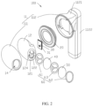
- FIG. 1 and FIG. 2 show an earphone 100 according to a first embodiment of this application.
- the earphone 100 can perform active noise cancellation to cancel noise in an ear canal, to improve sound effect and sound quality of the earphone 100.
- the earphone 100 may be an in-ear earphone, a semi-in-ear earphone, a headphone, or the like, and in particular, relates to a semi-in-ear earphone.
- the earphone 100 includes a housing 10, a speaker 20, a noise cancellation microphone 30, a dust filter 40, and a cosmetic mesh 50.
- the housing 10 is provided with inner space 13 that communicates with the outside.
- the speaker 20 and the noise cancellation microphone 30 are disposed in the inner space 13 (refer to FIG. 4 ) of the housing 10.
- the dust filter 40 and the cosmetic mesh 50 are disposed on the housing 10 and are located at a location at which the inner space 13 communicates with the outside, so that the inner space 13 communicates with the outside through the dust filter 40 and the cosmetic mesh 50.
- the housing 10 includes an outer housing 11 and a frame 12.
- the outer housing 11 is provided with the inner space 13 and a communication hole 14.
- the communication hole 14 is configured to communicate the inner space 13 with an outside world.
- the earphone 100 is worn on a human ear
- the communication hole 14 points to an ear canal of a human body.
- the frame 12 is disposed in the inner space 13 of the outer housing 11 and is disposed close to the communication hole 14.
- the noise cancellation microphone 30 is disposed on the frame 12.
- the dust filter 40 and the cosmetic mesh 50 are located between the outer housing 11 and the frame 12 and cover the communication hole 14.
- the outer housing 11 includes a front housing 111 and a rear housing 112.
- the front housing 111 is disposed on the rear housing 112, and the front housing 111 and the rear housing 112 jointly enclose the inner space 13.
- the frame 12 is disposed on the front housing 111.
- the speaker 20 is disposed on the front housing 111.
- the speaker 20 and the frame 12 divide the inner space 13 into a front cavity 131 and a rear cavity 132.
- the front cavity 131 is located between the speaker 20 and the frame 12.
- the rear cavity 132 is located between the speaker 20 and the rear housing 112.
- the noise cancellation microphone 30 is located in the front cavity 131.
- the communication hole 14 is disposed on the front housing 111.
- the communication hole 14 communicates the front cavity 131 with the outside world.
- the dust filter 40 and the cosmetic mesh 50 are disposed between the front housing 111 and the frame 12 and cover the communication hole 14.
- an inner wall of the frame 12 roughly matches an inner wall of the front housing 111.
- the frame 12 is provided with a communication surface 121 facing the communication hole 14.
- a sound-emitting hole 122 is provided on the communication surface 121.
- the sound-emitting hole 122 communicates the front cavity 131 with the communication hole 14.
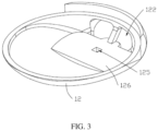
- the frame 12 is further provided with a sound pickup channel 123.
- the sound pickup channel 123 is formed with a sound pickup opening 124 on the communication surface 121, and the sound pickup channel 123 is further formed with a sound pickup hole 125 at another location of the frame 12.
- the noise cancellation microphone 30 is disposed on the frame 12 and covers the sound pickup hole 125.
- the sound pickup opening 124 is isolated from the sound-emitting hole 122, and the sound pickup channel 123 is isolated from (not communicates with) the front cavity 131 through the frame 12, to minimize impact of the speaker 20 on sound pickup of the noise cancellation microphone 30.
- the sound pickup opening 124 is located on a side that is of the communication surface 121 and that is away from the speaker 20. There are two sound-emitting holes 122, and the sound-emitting holes 122 are symmetrically disposed on the communication surface 121. The sound pickup opening 124 is located between the two sound-emitting holes 122. However, this is not limited. In another embodiment, there may alternatively be one or more sound-emitting holes 122.
- the speaker 20 is configured to emit a sound to the front cavity 131, to transmit the sound to the ear canal through the sound-emitting hole 122 and the communication hole 14.
- the noise cancellation microphone 30 is a feedback microphone (Feedback Mic, FB Mic, or Error Mic), and is configured to receive, pick up, and detect residual noise in an ear canal between the earphone and a human ear after the earphone is worn, and enable, by using an algorithm (a built-in unit of the noise cancellation microphone 30, another unit in the earphone 100, or an external processing unit), the speaker 20 of the earphone to release a reverse sound wave to cancel the noise.
- an algorithm a built-in unit of the noise cancellation microphone 30, another unit in the earphone 100, or an external processing unit
- An inner wall of the frame 12 is provided with a mounting surface 126 close to the sound-emitting hole 122.
- the sound pickup hole 125 is formed on the mounting surface 126 and is close to the communication surface 121.
- the noise cancellation microphone 30 is disposed on the mounting surface 126 through a connecting part 31, and the sound pickup hole 125 communicates with a sound pickup end of the noise cancellation microphone 30. In this way, noise in the ear canal is transmitted to the noise cancellation microphone 30 through the communication hole 14 and the sound pickup channel 123.
- the connecting part 31 may be an adhesive like a double-sided adhesive or glue.
- the dust filter 40 is disposed on the communication surface 121 and covers the sound-emitting hole 122 and the sound pickup opening 124.
- the cosmetic mesh 50 is disposed on the front housing 111 and completely covers the communication hole 14.
- the earphone 100 further includes a sealing part 60.
- the sealing part 60 is configured to seal the outer housing 11 and the frame 12 at the communication hole 14 and the communication surface 121.
- the sealing part 60 includes a first sealing part 61, a second sealing part 62, and a third sealing part 63.
- Both the dust filter 40 and the cosmetic mesh 50 are planar meshes whose shapes are similar to a shape of the communication surface 121.
- the first sealing part 61 is disposed between the dust filter 40 and the communication surface 121, to seal the dust filter 40 on the communication surface 121.
- the second sealing part 62 is disposed between the front housing 111 and the cosmetic mesh 50, so that the cosmetic mesh 50 is disposed on the front housing 111, and the communication hole 14 is sealed.
- the third sealing part 63 is disposed between the dust filter 40 and the cosmetic mesh 50, to implement sealing between the dust filter 40 and the cosmetic mesh 50.
- Each of the first sealing part 61 and the third sealing part 63 is provided with openings at respective locations relative to the sound-emitting hole 122 and the sound pickup opening 124, so that the sound-emitting hole 122 and the sound pickup opening 124 are separated at the communication hole 14 between the outer housing 11 and the frame 12. In this way, the sound emitted by the speaker 20 from the sound-emitting hole 122 has minimal impact on the noise cancellation microphone 30 in the sound pickup opening 124, so that the noise cancellation microphone 30 can receive the noise in the ear canal as much as possible.
- the second sealing part 62 is substantially ring-shaped, so that the cosmetic mesh 50 is disposed on a wall surface around the communication hole 14 of the front housing 111.
- Adhesives such as a double-sided adhesive or glue may be selected for the first sealing part 61, the second sealing part 62, and the third sealing part 63.
- the dust filter 40 is configured to prevent external dust from entering the earphone and affecting sound effect and sound quality of the earphone.
- the cosmetic mesh 50 is preferably a metal mesh, to improve style and mechanical reliability of the earphone, and prevent the inner dust filter 40, speaker 20, and noise cancellation microphone 30 from being damaged by an external force, for example, prevent an external sharp object from piercing.
- a damping of the cosmetic mesh 50 needs to be as small as possible.
- the rear housing 112 includes an earphone front end 1121 and an earphone rear end 1122.
- the earphone front end 1121 is used for mounting the speaker 20 and the front housing 111.
- the earphone rear end 1122 is convenient for a user to hold, so that the earphone 100 is worn on an ear of the user.
- the user holds the earphone rear end 1122 and wears, on the ear, the earphone front end 1121 provided with the front housing 111, so that a side provided with the communication hole 14 faces the ear canal.
- the noise cancellation microphone 30 receives noise in an ear canal, and the speaker 20 emits a sound with a reverse sound wave, so that the noise in the ear canal is eliminated from a sound heard by the human ear, thereby improving sound effect and sound quality of the earphone.
- the rear cavity 132 is configured to dispose another component of the earphone, for example, a circuit board configured to control the earphone, a battery module configured to store electric energy, a power input unit configured to communicate with an external power supply unit, a communication unit configured to perform signal transmission with the outside, or a call microphone configured to receive a sound made by the user.
- a circuit board configured to control the earphone
- a battery module configured to store electric energy
- a power input unit configured to communicate with an external power supply unit
- a communication unit configured to perform signal transmission with the outside
- a call microphone configured to receive a sound made by the user.
- the earphone 100 may be provided with a component and design that improve sound quality and wearing comfort in a common earphone, like an active noise cancellation microphone (Feedforward Mic or Ref Mic) or a pressure relief hole.
- a component and design that improve sound quality and wearing comfort in a common earphone, like an active noise cancellation microphone (Feedforward Mic or Ref Mic) or a pressure relief hole.
- the communication surface 121 faces the ear canal
- the independent sound pickup channel 123 is disposed on the frame 12 to enable the sound pickup opening 124 to be as close as possible to the ear canal
- the sound pickup opening 124 of the sound pickup channel 123 and the sound-emitting hole 122 are separated on the communication surface 121.
- the dust filter 40 is added, and the sound pickup opening 124 and the sound-emitting hole 122 between the communication hole 14 and the communication surface 121 are separated by the sealing part 60.
- the noise cancellation microphone 30 receives noise toward the ear canal through the sound pickup opening 124, so that the received noise can be as similar as possible to the noise in the ear canal. This optimizes a condition for noise cancellation debugging, achieves better noise cancellation effect, and achieves better dustproof effect.
- FIG. 5 shows an earphone 200 according to a second embodiment of this application.
- the earphone 200 has a same structure as the earphone 100, and includes the housing 10, the speaker 20, the noise cancellation microphone 30, the dust filter 40, and the cosmetic mesh 50.
- a main difference from the earphone 100 in the first embodiment shown in FIG. 1 lies in that structures of the dust filter 40, the cosmetic mesh 50, and the sealing part 60 are different.
- the dust filter 40 covers only the sound-emitting hole 122, but does not cover the sound pickup opening 124.
- the cosmetic mesh 50 is in an outwardly protruding shape.
- the third sealing part 63 in the sealing part 60 is substantially ring-shaped, to connect an outer periphery of the cosmetic mesh 50 to an outer periphery of the dust filter 40 in a sealed manner.
- the communication surface 121 faces the ear canal, the independent sound pickup channel 123 is disposed on the frame 12, and the sound pickup opening 124 of the sound pickup channel 123 and the sound-emitting hole 122 are separated on the communication surface 121.
- the noise cancellation microphone 30 receives noise toward the ear canal through the sound pickup opening 124, so that the received noise can be as similar as possible to the noise in the ear canal. This optimizes a condition for noise cancellation debugging, and achieves better noise cancellation effect.
- FIG. 6 shows an earphone 300 according to a third embodiment of this application.
- the earphone 300 has a same structure as the earphone 200, and includes the housing 10, the speaker 20, the noise cancellation microphone 30, the dust filter 40, and the cosmetic mesh 50.
- a main difference from the earphone 200 in the second embodiment shown in FIG. 5 lies in that a structure of the dust filter 40 is different.
- aperture density of an area of the dust filter 40 that covers the sound-emitting hole 122 is different from aperture density of an area of the dust filter 40 that covers the sound pickup opening 124. Therefore, an aperture of the dust filter 40 at the sound pickup opening 124 is larger, and in this case, a sound resistance of the dust filter 40 at the sound pickup opening 124 is lower (less than or equal to 10 MKS Rayls).
- the communication surface 121 faces the ear canal, the independent sound pickup channel 123 is disposed on the frame 12, and the sound pickup opening 124 of the sound pickup channel 123 and the sound-emitting hole 122 are separated on the communication surface 121.
- the dust filter 40 is added, and a damping of the dust filter 40 at the sound pickup opening 124 is reduced through adjustment.
- the noise cancellation microphone 30 receives noise toward the ear canal through the sound pickup opening 124, so that the received noise can be as similar as possible to the noise in the ear canal. This optimizes a condition for noise cancellation debugging, and achieves better noise cancellation effect.
- FIG. 7 shows an earphone 400 according to a fourth embodiment of this application.
- the earphone 400 has a same structure as the earphone 100, and includes the housing 10, the speaker 20, the noise cancellation microphone 30, and the dust filter 40.
- a main difference from the earphone 100 in the second embodiment shown in FIG. 1 lies in that the cosmetic mesh 50 is not provided.
- the dust filter 40 may be made of a material with high mechanical strength, to simultaneously implement functions of the dust filter 40 and the cosmetic mesh 50 in the earphone 100.
- the sealing part 60 includes only the first sealing part 61 and the second sealing part 62.
- the first sealing part 61 is disposed between the dust filter 40 and the communication surface 121, to seal the dust filter 40 on the communication surface 121.
- the second sealing part 62 is disposed between the front housing 111 and the dust filter 40, so that the dust filter 40 is disposed on the front housing 111, and the communication hole 14 is sealed.
- aperture density on the dust filter 40 in the earphone 400 may further be designed as that an aperture for covering the sound-emitting hole 122 is greater than an aperture for covering the sound pickup opening 124. In this case, a sound resistance of the dust filter 40 at the sound pickup opening 124 is lower.
- the dust filters 40 may be disposed on a hole wall or on a surface of the communication surface 121).
- the sealing part 60 includes only the second sealing part 62, and the second sealing part 62 is disposed between the front housing 111 and the communication surface 121, to seal the communication hole 14 on the front housing 111 through the communication surface 121.
- the communication surface 121 faces the ear canal, the independent sound pickup channel 123 is disposed on the frame 12, and the sound pickup opening 124 of the sound pickup channel 123 and the sound-emitting hole 122 are separated on the communication surface 121.
- the dust filter 40 is added, and a damping of the dust filter 40 at the sound pickup opening 124 is reduced through adjustment.
- the noise cancellation microphone 30 receives noise toward the ear canal through the sound pickup opening 124, so that the received noise can be as similar as possible to the noise in the ear canal. This optimizes a condition for noise cancellation debugging, and achieves better noise cancellation effect.
- This application further provides a terminal apparatus, where the terminal apparatus has the earphone 100, the earphone 200, or the earphone 300.
- the terminal apparatus may be glasses, an AR apparatus, a VR apparatus, or another product with audio effect.
Landscapes
- Engineering & Computer Science (AREA)
- Physics & Mathematics (AREA)
- Acoustics & Sound (AREA)
- Signal Processing (AREA)
- Manufacturing & Machinery (AREA)
- Soundproofing, Sound Blocking, And Sound Damping (AREA)
Applications Claiming Priority (2)
| Application Number | Priority Date | Filing Date | Title |
|---|---|---|---|
| CN202011612556.8A CN114697791A (zh) | 2020-12-30 | 2020-12-30 | 耳机 |
| PCT/CN2021/139404 WO2022143234A1 (zh) | 2020-12-30 | 2021-12-18 | 耳机 |
Publications (2)
| Publication Number | Publication Date |
|---|---|
| EP4247001A1 true EP4247001A1 (de) | 2023-09-20 |
| EP4247001A4 EP4247001A4 (de) | 2024-05-22 |
Family
ID=82131739
Family Applications (1)
| Application Number | Title | Priority Date | Filing Date |
|---|---|---|---|
| EP21913975.5A Pending EP4247001A4 (de) | 2020-12-30 | 2021-12-18 | Kopfhörer |
Country Status (4)
| Country | Link |
|---|---|
| US (1) | US12407973B2 (de) |
| EP (1) | EP4247001A4 (de) |
| CN (3) | CN119815237A (de) |
| WO (1) | WO2022143234A1 (de) |
Families Citing this family (3)
| Publication number | Priority date | Publication date | Assignee | Title |
|---|---|---|---|---|
| USD1063898S1 (en) * | 2022-11-18 | 2025-02-25 | Guangdong Oppo Mobile Telecommunications Corp., Ltd. | Wireless earphone |
| USD1078691S1 (en) * | 2023-10-20 | 2025-06-10 | Jvckenwood Corporation | Earphone |
| USD1047982S1 (en) * | 2024-08-06 | 2024-10-22 | Hanhua Deng | Wireless headset |
Family Cites Families (15)
| Publication number | Priority date | Publication date | Assignee | Title |
|---|---|---|---|---|
| US8571228B2 (en) * | 2009-08-18 | 2013-10-29 | Bose Corporation | Feedforward ANR device acoustics |
| GB2493206B (en) * | 2011-07-29 | 2013-10-02 | Incus Lab Ltd | Earphone arrangements |
| KR101469908B1 (ko) * | 2013-08-21 | 2014-12-08 | 크레신 주식회사 | 이어폰 |
| TWM501702U (zh) * | 2015-01-16 | 2015-05-21 | Jetvox Acoustic Corp | 降噪耳機 |
| KR101693268B1 (ko) | 2015-04-10 | 2017-01-05 | 해보라 주식회사 | 이어셋 |
| CN106101895A (zh) * | 2016-06-30 | 2016-11-09 | 华峰君 | 一种降噪耳机及控制噪音消除电路开启或关闭的方法 |
| US10257602B2 (en) * | 2017-08-07 | 2019-04-09 | Bose Corporation | Earbud insertion sensing method with infrared technology |
| CN109688513A (zh) * | 2018-11-19 | 2019-04-26 | 恒玄科技(上海)有限公司 | 无线主动降噪耳机及双主动降噪耳机通话数据处理方法 |
| CN210042133U (zh) | 2019-06-28 | 2020-02-07 | 潍坊歌尔电子有限公司 | 一种降噪耳机 |
| CN209964254U (zh) | 2019-06-28 | 2020-01-17 | 潍坊歌尔电子有限公司 | 一种降噪tws蓝牙耳机 |
| CN210609653U (zh) * | 2020-01-08 | 2020-05-22 | 东莞市逸音电子科技有限公司 | 一种前腔音嘴内置麦克风降噪耳机 |
| CN211406247U (zh) * | 2020-03-17 | 2020-09-01 | 广州由我科技股份有限公司 | 一种半入耳式耳机 |
| CN211406246U (zh) * | 2020-03-17 | 2020-09-01 | 广州由我科技股份有限公司 | 一种蓝牙耳机 |
| CN211152190U (zh) * | 2020-03-26 | 2020-07-31 | 北京爱德发科技有限公司 | 一种半入耳式主动降噪耳机 |
| CN211152189U (zh) * | 2020-03-26 | 2020-07-31 | 北京爱德发科技有限公司 | 一种半入耳式主动降噪耳机 |
-
2020
- 2020-12-30 CN CN202411981658.5A patent/CN119815237A/zh active Pending
- 2020-12-30 CN CN202210672333.3A patent/CN115119094A/zh active Pending
- 2020-12-30 CN CN202011612556.8A patent/CN114697791A/zh active Pending
-
2021
- 2021-12-18 US US18/270,270 patent/US12407973B2/en active Active
- 2021-12-18 EP EP21913975.5A patent/EP4247001A4/de active Pending
- 2021-12-18 WO PCT/CN2021/139404 patent/WO2022143234A1/zh not_active Ceased
Also Published As
| Publication number | Publication date |
|---|---|
| US12407973B2 (en) | 2025-09-02 |
| US20240107221A1 (en) | 2024-03-28 |
| CN115119094A (zh) | 2022-09-27 |
| WO2022143234A1 (zh) | 2022-07-07 |
| EP4247001A4 (de) | 2024-05-22 |
| CN119815237A (zh) | 2025-04-11 |
| CN114697791A (zh) | 2022-07-01 |
Similar Documents
| Publication | Publication Date | Title |
|---|---|---|
| US12284475B2 (en) | In-ear headphone | |
| RU2713042C1 (ru) | Способ модификации устройства для защиты органов слуха и устройство для защиты органов слуха | |
| US12407973B2 (en) | Earphone | |
| US8649525B2 (en) | System for hearing protectors | |
| AU2010271259B2 (en) | Bone conduction communications headset with hearing protection | |
| US20210136477A1 (en) | Wireless earphone | |
| CN106454574A (zh) | 耳塞式耳机麦克风模块 | |
| US20150078570A1 (en) | Handset or Headset | |
| WO2023150170A1 (en) | Open-ear headphone | |
| WO2025045176A1 (zh) | 耳机及音频装置 | |
| US12294828B2 (en) | Wireless earphone | |
| US20110058696A1 (en) | Advanced low-power talk-through system and method | |
| CN214481199U (zh) | 一种头戴式耳机模组及头戴式耳机 | |
| CN212435899U (zh) | 一种降噪组件及耳机 | |
| EP3664466A1 (de) | Ohrhörer mit rückkopplungsmikrofon zur aktiven rauschunterdrückung, das an der rückseite einer lautsprechermembran angeordnet ist, und verfahren zur herstellung solch eines ohrhörers | |
| US11564841B2 (en) | Hearing protection headset | |
| US20250365529A1 (en) | Earpiece with Debris Ingress Protection | |
| WO2025199742A1 (en) | Earphone | |
| CN218772363U (zh) | 入耳式耳机 | |
| CN222484879U (zh) | 开放式耳机 | |
| CN219248018U (zh) | 一种防啸叫开放式降噪耳机 | |
| EP4231662A1 (de) | Hörgerät mit aktiver geräuschkontrolle | |
| WO2025245331A1 (en) | Earpiece with debris ingress protection |
Legal Events
| Date | Code | Title | Description |
|---|---|---|---|
| STAA | Information on the status of an ep patent application or granted ep patent |
Free format text: STATUS: THE INTERNATIONAL PUBLICATION HAS BEEN MADE |
|
| PUAI | Public reference made under article 153(3) epc to a published international application that has entered the european phase |
Free format text: ORIGINAL CODE: 0009012 |
|
| STAA | Information on the status of an ep patent application or granted ep patent |
Free format text: STATUS: REQUEST FOR EXAMINATION WAS MADE |
|
| 17P | Request for examination filed |
Effective date: 20230613 |
|
| AK | Designated contracting states |
Kind code of ref document: A1 Designated state(s): AL AT BE BG CH CY CZ DE DK EE ES FI FR GB GR HR HU IE IS IT LI LT LU LV MC MK MT NL NO PL PT RO RS SE SI SK SM TR |
|
| DAV | Request for validation of the european patent (deleted) | ||
| DAX | Request for extension of the european patent (deleted) | ||
| A4 | Supplementary search report drawn up and despatched |
Effective date: 20240423 |
|
| RIC1 | Information provided on ipc code assigned before grant |
Ipc: H04R 1/10 20060101AFI20240417BHEP |