EP4247010A1 - Dispositif auditif - Google Patents
Dispositif auditif Download PDFInfo
- Publication number
- EP4247010A1 EP4247010A1 EP23161916.4A EP23161916A EP4247010A1 EP 4247010 A1 EP4247010 A1 EP 4247010A1 EP 23161916 A EP23161916 A EP 23161916A EP 4247010 A1 EP4247010 A1 EP 4247010A1
- Authority
- EP
- European Patent Office
- Prior art keywords
- isolator
- disposed
- sleeve
- housing
- rear housing
- Prior art date
- Legal status (The legal status is an assumption and is not a legal conclusion. Google has not performed a legal analysis and makes no representation as to the accuracy of the status listed.)
- Pending
Links
Images




Classifications
-
- H—ELECTRICITY
- H04—ELECTRIC COMMUNICATION TECHNIQUE
- H04R—LOUDSPEAKERS, MICROPHONES, GRAMOPHONE PICK-UPS OR LIKE ACOUSTIC ELECTROMECHANICAL TRANSDUCERS; ELECTRIC HEARING AIDS; PUBLIC ADDRESS SYSTEMS
- H04R1/00—Details of transducers, loudspeakers or microphones
- H04R1/10—Earpieces; Attachments therefor ; Earphones; Monophonic headphones
- H04R1/1083—Reduction of ambient noise
-
- H—ELECTRICITY
- H04—ELECTRIC COMMUNICATION TECHNIQUE
- H04R—LOUDSPEAKERS, MICROPHONES, GRAMOPHONE PICK-UPS OR LIKE ACOUSTIC ELECTROMECHANICAL TRANSDUCERS; ELECTRIC HEARING AIDS; PUBLIC ADDRESS SYSTEMS
- H04R25/00—Electric hearing aids
- H04R25/45—Prevention of acoustic reaction, i.e. acoustic oscillatory feedback
- H04R25/456—Prevention of acoustic reaction, i.e. acoustic oscillatory feedback mechanically
-
- H—ELECTRICITY
- H04—ELECTRIC COMMUNICATION TECHNIQUE
- H04R—LOUDSPEAKERS, MICROPHONES, GRAMOPHONE PICK-UPS OR LIKE ACOUSTIC ELECTROMECHANICAL TRANSDUCERS; ELECTRIC HEARING AIDS; PUBLIC ADDRESS SYSTEMS
- H04R1/00—Details of transducers, loudspeakers or microphones
- H04R1/02—Casings; Cabinets ; Supports therefor; Mountings therein
-
- H—ELECTRICITY
- H04—ELECTRIC COMMUNICATION TECHNIQUE
- H04R—LOUDSPEAKERS, MICROPHONES, GRAMOPHONE PICK-UPS OR LIKE ACOUSTIC ELECTROMECHANICAL TRANSDUCERS; ELECTRIC HEARING AIDS; PUBLIC ADDRESS SYSTEMS
- H04R1/00—Details of transducers, loudspeakers or microphones
- H04R1/08—Mouthpieces; Microphones; Attachments therefor
-
- H—ELECTRICITY
- H04—ELECTRIC COMMUNICATION TECHNIQUE
- H04R—LOUDSPEAKERS, MICROPHONES, GRAMOPHONE PICK-UPS OR LIKE ACOUSTIC ELECTROMECHANICAL TRANSDUCERS; ELECTRIC HEARING AIDS; PUBLIC ADDRESS SYSTEMS
- H04R1/00—Details of transducers, loudspeakers or microphones
- H04R1/08—Mouthpieces; Microphones; Attachments therefor
- H04R1/083—Special constructions of mouthpieces
-
- H—ELECTRICITY
- H04—ELECTRIC COMMUNICATION TECHNIQUE
- H04R—LOUDSPEAKERS, MICROPHONES, GRAMOPHONE PICK-UPS OR LIKE ACOUSTIC ELECTROMECHANICAL TRANSDUCERS; ELECTRIC HEARING AIDS; PUBLIC ADDRESS SYSTEMS
- H04R1/00—Details of transducers, loudspeakers or microphones
- H04R1/10—Earpieces; Attachments therefor ; Earphones; Monophonic headphones
- H04R1/1016—Earpieces of the intra-aural type
-
- H—ELECTRICITY
- H04—ELECTRIC COMMUNICATION TECHNIQUE
- H04R—LOUDSPEAKERS, MICROPHONES, GRAMOPHONE PICK-UPS OR LIKE ACOUSTIC ELECTROMECHANICAL TRANSDUCERS; ELECTRIC HEARING AIDS; PUBLIC ADDRESS SYSTEMS
- H04R1/00—Details of transducers, loudspeakers or microphones
- H04R1/20—Arrangements for obtaining desired frequency or directional characteristics
- H04R1/22—Arrangements for obtaining desired frequency or directional characteristics for obtaining desired frequency characteristic only
- H04R1/28—Transducer mountings or enclosures modified by provision of mechanical or acoustic impedances, e.g. resonator, damping means
- H04R1/2869—Reduction of undesired resonances, i.e. standing waves within enclosure, or of undesired vibrations, i.e. of the enclosure itself
-
- H—ELECTRICITY
- H04—ELECTRIC COMMUNICATION TECHNIQUE
- H04R—LOUDSPEAKERS, MICROPHONES, GRAMOPHONE PICK-UPS OR LIKE ACOUSTIC ELECTROMECHANICAL TRANSDUCERS; ELECTRIC HEARING AIDS; PUBLIC ADDRESS SYSTEMS
- H04R25/00—Electric hearing aids
- H04R25/60—Mounting or interconnection of hearing aid parts, e.g. inside tips, housings or to ossicles
- H04R25/604—Mounting or interconnection of hearing aid parts, e.g. inside tips, housings or to ossicles of acoustic or vibrational transducers
-
- H—ELECTRICITY
- H04—ELECTRIC COMMUNICATION TECHNIQUE
- H04R—LOUDSPEAKERS, MICROPHONES, GRAMOPHONE PICK-UPS OR LIKE ACOUSTIC ELECTROMECHANICAL TRANSDUCERS; ELECTRIC HEARING AIDS; PUBLIC ADDRESS SYSTEMS
- H04R2225/00—Details of deaf aids covered by H04R25/00, not provided for in any of its subgroups
- H04R2225/021—Behind the ear [BTE] hearing aids
- H04R2225/0216—BTE hearing aids having a receiver in the ear mould
-
- H—ELECTRICITY
- H04—ELECTRIC COMMUNICATION TECHNIQUE
- H04R—LOUDSPEAKERS, MICROPHONES, GRAMOPHONE PICK-UPS OR LIKE ACOUSTIC ELECTROMECHANICAL TRANSDUCERS; ELECTRIC HEARING AIDS; PUBLIC ADDRESS SYSTEMS
- H04R2460/00—Details of hearing devices, i.e. of ear- or headphones covered by H04R1/10 or H04R5/033 but not provided for in any of their subgroups, or of hearing aids covered by H04R25/00 but not provided for in any of its subgroups
- H04R2460/01—Hearing devices using active noise cancellation
Definitions
- Hearing devices that are disposed in an ear of a wearer or inserted into an opening of an ear canal of the wearer typically include a housing or shell with electronic components such as a receiver (i.e., speaker) disposed within the housing.
- the receiver is adapted to provide acoustic information in the form of acoustic energy to the wearer's ear canal from a controller either disposed within the housing of the hearing device or connected to the hearing device by a wired or wireless connection.
- This acoustic information can include music or speech from a recording or other source.
- the acoustic information provided to the wearer can include ambient sounds such as speech from a person or persons that are speaking in proximity to the wearer.
- Some hearing devices also include a microphone disposed within the housing. Such microphone can be utilized to detect the wearer's voice and provide a microphone signal to the receiver, which in turn provides acoustic energy to the ear that includes an amplified version of the wearer's voice.
- the present disclosure provides various embodiments of a hearing device and a system that includes such device.
- the hearing device includes an enclosure having a front housing and a rear housing.
- An isolator is disposed between the front and rear housings.
- the isolator can include a body and a sleeve disposed on the body.
- the device further includes a microphone disposed in the rear housing and a receiver disposed in the front housing.
- a microphone port extends between an inlet disposed in the rear housing and an outlet that is acoustically connected to an inlet of the microphone.
- the isolator can be adapted to reduce vibrations caused by the receiver that can affect a microphone signal produced by the microphone.
- the present disclosure provides a hearing device that includes an enclosure extending along an enclosure axis and including a front housing and a rear housing, where the front housing extends along the enclosure axis between a first end and a second end.
- the first end is adapted to be disposed at least partially within an ear canal of a wearer
- the rear housing extends along the enclosure axis between a first end and a second end.
- the hearing device further includes an isolator disposed between the front housing and the rear housing, where the isolator includes a body and a sleeve disposed on a side surface of the body. The second end of the front housing and the second end of the rear housing are connected to the sleeve of the isolator.
- the device also includes a microphone disposed in the rear housing and a microphone port extending between an inlet disposed in the rear housing and an outlet that is acoustically connected to an inlet of the microphone.
- the device further includes a receiver disposed in the front housing and an acoustic port extending between the receiver and an opening disposed in the first end of the front housing. The acoustic port acoustically connects the receiver to the opening.
- the present disclosure provides a hearing device system that includes a hearing device, a hearing module, and a cable that connects the hearing device to the hearing module.
- the hearing device includes an enclosure extending along an enclosure axis and including a front housing and a rear housing, where the front housing extends along the enclosure axis between a first end and a second end, where the first end is adapted to be disposed at least partially within an ear canal of a wearer, and further where the rear housing extends along the enclosure axis between a first end and a second end.
- the hearing device further includes an isolator disposed between the front housing and the rear housing, where the isolator includes a body and a sleeve disposed on a side surface of the body, where the second end of the front housing and the second end of the rear housing are connected to the sleeve of the isolator.
- the hearing device further includes a microphone disposed in the rear housing and a microphone port extending between an inlet disposed in the rear housing and an outlet acoustically connected to an inlet of the microphone.
- the device also includes a receiver disposed in the front housing and an acoustic port extending between the receiver and an opening disposed in the first end of the front housing, where the acoustic port acoustically connects the receiver to the opening.
- the hearing module is adapted to be disposed between an ear and a skull of the wearer, where the hearing module includes a module housing and electronic components disposed within the module housing.
- the present disclosure provides a method that includes forming a body of an isolator; disposing a sleeve onto a side surface of the body of the isolator; and disposing a microphone at least partially within a rear housing, where the rear housing includes a first end and a second end.
- the method further includes disposing a receiver within a front housing, where the front housing includes a first end and a second end, and where the first end is adapted to be disposed at least partially within an ear canal of a wearer.
- the method further includes connecting the second end of the front housing to the sleeve of the isolator; and connecting the second end of the rear housing to the sleeve of the isolator, where the front housing, the isolator, and the rear housing define an enclosure that extends along an enclosure axis.
- a number e.g., up to 50
- the number e.g., 50
- the present disclosure provides various embodiments of a hearing device and a system that includes such device.
- the hearing device includes an enclosure having a front housing and a rear housing.
- An isolator is disposed between the front and rear housings.
- the isolator can include a body and a sleeve disposed on the body.
- the device further includes a microphone disposed in the rear housing and a receiver disposed in the front housing.
- a microphone port extends between an inlet disposed in the rear housing and an outlet that is acoustically connected to an inlet of the microphone.
- the isolator can be adapted to reduce vibrations caused by the receiver that can affect a microphone signal produced by the microphone.
- the isolator that is disposed between the front and rear housings can reduce vibrations from the receiver and the enclosure. Such vibration reduction can enable placement of the microphone inside the rear housing without an increase in noise in the microphone signal that can be caused by vibration of the receiver.
- the isolator can include a body and a sleeve disposed on the body. In one or more embodiments, the sleeve can be over-molded onto the body, which can enhance robustness of the isolator and the enclosure of the device and increase manufacturability of the device.
- a hearing device that includes an enclosure extending along an enclosure axis and including a front housing and a rear housing, where the front housing extends along the enclosure axis between a first end and a second end. The first end is adapted to be disposed at least partially within an ear canal of a wearer, and the rear housing extends along the enclosure axis between a first end and a second end.
- the hearing device further includes an isolator disposed between the front housing and the rear housing, where the isolator includes a body and a sleeve disposed on a side surface of the body. The second end of the front housing and the second end of the rear housing are connected to the sleeve of the isolator.
- the device also includes a microphone disposed in the rear housing and a microphone port extending between an inlet disposed in the rear housing and an outlet that is acoustically connected to an inlet of the microphone.
- the device further includes a receiver disposed in the front housing and an acoustic port extending between the receiver and an opening disposed in the first end of the front housing. The acoustic port acoustically connects the receiver to the opening.
- Example Ex2 The device of Ex1, where the sleeve is over-molded onto the side surface of the body of the isolator.
- Example Ex3 The device of one or more of Ex1 to Ex2, where the isolator further includes a flange that extends from the side surface, where the sleeve is in contact with the flange.
- Example Ex4 The device of Ex3, where the sleeve includes a first portion that is connected to the front housing and a second portion that is connected to the rear housing, where the flange is disposed between the first portion and the second portion of the sleeve.
- Example Ex5. The device of one or more of Ex1 to Ex4, where the body of the isolator includes at least one of a thermoplastic polymer, thermoset polymer, thermoplastic elastomer, or photopolymer.
- Example Ex6 The device of one or more of Ex1 to Ex5, where the body of the isolator includes a hardness value of at least 20 durometer Shore OO.
- Example Ex7 The device of one or more of Ex1 to Ex6, where the body of the isolator includes a hardness value of no greater than 80 durometer Shore A.
- Example Ex8 The device of one or more of Ex1 to Ex7, where a hardness value of the sleeve of the isolator is greater than a hardness value of the body of the isolator.
- Example Ex9 The device of one or more of Ex1 to Ex8, further including an earbud connected to the first end of the front housing.
- Example Ex10 The device of Ex9, where the front housing includes a concentric flange disposed on an outer surface of the front housing, where the concentric flange is adapted to engage the earbud.
- Example Ex11 The device of one or more of Ex9 to Ex10, where an opening in the earbud is aligned along the enclosure axis with the opening in the first end of the front housing.
- Example Ex12 The device of one or more of Ex1 to Ex11, where the sleeve of the isolator further includes a first rib that extends toward the first end of the front housing along the enclosure axis, where the first rib is adapted to be inserted into the second end of the front housing.
- Example Ex13 The device of Ex12, where the sleeve of the isolator further includes a second rib extending toward the first end of the rear housing along the enclosure axis, where the second rib is adapted to be inserted into the first end of the rear housing.
- Example Ex14 The device of Ex13, where the sleeve of the isolator further includes a ledge that extends from the first rib to a perimeter of the sleeve, where an end surface of the second end of the front housing is adapted to engage the ledge.
- Example Ex15 The device of Ex14, where the sleeve of the isolator further includes a second ledge that extends from the second rib to the perimeter of the sleeve, where an end surface of the second end of the rear housing is adapted to engage the ledge.
- Example Ex16 The device of one or more of Ex1 to Ex15, further including a connector port disposed in the first end of the rear housing and adapted to receive an end of a cable.
- a hearing device system that includes a hearing device, a hearing module, and a cable that connects the hearing device to the hearing module.
- the hearing device includes an enclosure extending along an enclosure axis and including a front housing and a rear housing, where the front housing extends along the enclosure axis between a first end and a second end, where the first end is adapted to be disposed at least partially within an ear canal of a wearer, and further where the rear housing extends along the enclosure axis between a first end and a second end.
- the hearing device further includes an isolator disposed between the front housing and the rear housing, where the isolator includes a body and a sleeve disposed on a side surface of the body, where the second end of the front housing and the second end of the rear housing are connected to the sleeve of the isolator.
- the hearing device further includes a microphone disposed in the rear housing and a microphone port extending between an inlet disposed in the rear housing and an outlet acoustically connected to an inlet of the microphone.
- the device also includes a receiver disposed in the front housing and an acoustic port extending between the receiver and an opening disposed in the first end of the front housing, where the acoustic port acoustically connects the receiver to the opening.
- the hearing module is adapted to be disposed between an ear and a skull of the wearer, where the hearing module includes a module housing and electronic components disposed within the module housing.
- Example Ex18 The system of Ex17, where the electronic components of the hearing module include a controller that is operatively connected to the hearing device.
- Example Ex19 The system of Ex18, where the controller is adapted to direct a noise canceling signal to the receiver of the hearing device that is based upon a noise signal received from the microphone of the hearing device, where the receiver is adapted to direct a noise canceling acoustic wave into an ear canal of a wearer of the hearing device that is based upon the noise canceling signal from the controller.
- Example Ex20 A method that includes forming a body of an isolator; disposing a sleeve onto a side surface of the body of the isolator; and disposing a microphone at least partially within a rear housing, where the rear housing includes a first end and a second end.
- the method further includes disposing a receiver within a front housing, where the front housing includes a first end and a second end, and where the first end is adapted to be disposed at least partially within an ear canal of a wearer.
- the method further includes connecting the second end of the front housing to the sleeve of the isolator; and connecting the second end of the rear housing to the sleeve of the isolator, where the front housing, the isolator, and the rear housing define an enclosure that extends along an enclosure axis.
- Example Ex21 The method of Ex20, further including disposing a microphone port in the rear housing that extends between an inlet disposed in the rear housing and an outlet disposed adjacent to the microphone.
- Example Ex22 The method of one or more of Ex20 to Ex21, where forming the body of the isolator includes molding the body of the isolator.
- Example Ex23 The method of one or more of Ex20 to Ex22, where disposing the sleeve onto the side surface of the body of the isolator includes over-molding the sleeve onto the side surface of the body of the isolator.
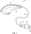
- FIG. 1 is a schematic perspective view of one embodiment of a hearing device system 10.
- the system 10 includes a hearing device 12, a hearing module 14, and a cable 16 that connects the hearing device to the hearing module.
- the hearing module 14 is adapted to be disposed between an ear and a skull of a wearer.
- the hearing module 14 includes a module housing 18 and electronic components (electronic components 20 of FIG. 7 ) disposed within the module housing.
- the hearing device 12 can include any suitable device that can provide acoustic energy to a wearer using any suitable technique, e.g., by directing sound into the ear of the wearer, bone conduction, implants, etc.
- the hearing device 12 can include over-the-ear or in-ear headphones, an earpiece, etc.
- the system 10 can include a hearing assistance device such as behind-the-ear (BTE), in-the-ear (ITE), in-the-canal (ITC), or completely-in-the-canal (CIC) type hearing devices. It is understood that behind-the-ear type hearing devices can reside substantially behind the ear or over the ear.
- Such devices can include receivers associated with an electronics portion of the behind-the-ear device, or receivers disposed in the ear canal of the user. Such devices are also known as receiver-in-the-canal (RIC) or receiver-in-the-ear (RITE) hearing devices.
- RIC receiver-in-the-canal
- RITE receiver-in-the-ear
- the hearing device 12 includes an enclosure 22 that extends along an enclosure axis 2.
- the enclosure 22 includes a front housing 24 and a rear housing 26.
- the front housing 24 extends along the enclosure axis 2 between a first end 28 and a second end 30.
- the rear housing 26 extends along the enclosure axis 2 between a first end 32 and a second end 34.
- the device 12 also includes an isolator 36 disposed between the front housing 24 and the rear housing 26.
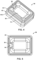
- the isolator 36 includes a body 38 and a sleeve 40 disposed on the body ( FIG. 4 ).
- the sleeve 40 is disposed on a side surface 42 ( FIG. 6 ) of the body 38.
- the second end 30 of the front housing 24 and the second end 34 of the rear housing 26 are connected to the sleeve 40 of the isolator 36.
- the hearing device 12 includes a sensor 44 disposed in the rear housing 26 and a receiver 46 disposed in the front housing 26.
- the sensor 44 includes a microphone (referred to herein as microphone 44).
- microphone 44 a microphone
- one or more additional components and/or circuitry can be disposed within the enclosure 22, e.g., at least one of a controller, amplifier, filter, GMR, switch, telecoil, sensor, or inward facing microphone.
- the device 12 further includes an acoustic port 48 that extends between the receiver 46 and an opening 50 disposed in the first end 28 of the front housing 24.
- the acoustic port 48 acoustically connects the receiver 46 to the opening 50, i.e., the acoustic port is adapted to direct acoustic energy between the receiver and the opening.
- the device 12 includes a microphone port 52 that extends between an inlet 54 disposed in the rear housing 26 and an outlet 56 that is acoustically connected to an inlet 96 of the microphone 44.
- the microphone port 52 acoustically connects the microphone 44 to the inlet 54 of the microphone port.
- the electronic components disposed within the enclosure 22 can also include one or more telecoils 98 ( FIG. 7 ). Such telecoil 98 can be electrically connected to one or more electronic components 20 disposed within the hearing module 14 using any suitable technique, e.g., by cable 16. Any suitable telecoil 98 or antenna can be disposed within the enclosure 22. By placing the microphone 44 in a rear-facing position as shown, additional space within the enclosure 22 can be provided for additional electronic components such as telecoils 98. Further, in one or more embodiments, placement of the telecoil 98 in the hearing device 12 can provide a more reliable signal to the wearer. In one or more embodiments, one or more additional telecoils can be disposed in the hearing module 14.
- the front housing 24 is sized such that at least a portion of its first end 28 can be disposed within an opening of the ear canal of the wearer.
- the first end 28 of the front housing 24 is adapted to be disposed at least partially within the ear canal.
- the hearing device 12 can include an earbud 62 ( FIG. 1 ) connected to the first end 28 of the front housing 24.
- the earbud 62 can take any suitable shape and having any suitable dimensions.
- the earbud 62 is integral with the front housing 24, i.e., formed as a single part with the front housing during the manufacturing process.
- the earbud 62 can be manufactured separately from the front housing 24 and connected to the front housing using any suitable technique.
- the earbud 62 includes an opening 66 that, in one or more embodiments, is aligned along the enclosure axis 2 with the opening 50 in the first end 28 of the front housing 24.
- the front housing 24 can include one or more flanges 64 ( FIG. 3 ) that are adapted to retain the earbud 62.
- the front housing 24 can include any suitable number of flanges 64.
- each flange 64 can take any suitable shape and have any suitable dimensions.
- one or more of the flanges 64 can be a concentric flange.
- the front housing 24 can include any suitable material, e.g., at least one of a polymeric material, metallic material, or ceramic material. Suitable polymeric materials include thermoplastic polymers (e.g., thermoplastic polyurethanes, thermoplastic elastomers), thermoset polymers, photopolymers, etc. In one or more embodiments, the front housing 24 can include the same material as the rear housing 26. Further, in one or more embodiments, the front housing 24 can include the same material as the material of the body 38 of the isolator 36. Further, the front housing 24 can be manufactured utilizing any suitable technique, e.g., molding, injection molding, 3D printing, die-casting, metal injection molding, sintering, stamping, casting, etc.
- suitable technique e.g., molding, injection molding, 3D printing, die-casting, metal injection molding, sintering, stamping, casting, etc.
- the rear housing 26 of the enclosure 22 extends along the enclosure axis 2 between the first end 32 and the second end 34.
- the rear housing 26 can take any suitable shape have any suitable dimensions.
- the rear housing 26 can include any suitable material, e.g., at least one of a polymeric material, metallic material, or ceramic material. Suitable polymeric materials include thermoplastic polymers (e.g., thermoplastic polyurethanes, thermoplastic elastomers), thermoset polymers, photopolymers, etc.
- the rear housing 26 can include the same material as the front housing 24. Further, in one or more embodiments, the rear housing 26 can include the same material as the material of the body 38 of the isolator 36. Further, the rear housing 26 can be manufactured utilizing any suitable technique, e.g., molding, injection molding, 3D printing, die-casting, metal injection molding, sintering, stamping, casting, etc.
- the rear housing 26 can include a connector port 68 disposed in the first end 32 of the rear housing that extends between the first end and the microphone 44 disposed within the rear housing.
- the connector port 68 can be adapted to receive an end 70 of cable 16 ( FIG. 1 ) that connects the hearing device 12 to the hearing module 14 such that the cable can connect the receiver 46, the microphone 44, and any other circuitry disposed within the enclosure 22 to circuitry disposed within the hearing module 14.
- the connector port 68 can extend through the isolator 36 such that the cable 16 can be electrically connected to the receiver 46.
- the front housing 24 and the rear housing 26 can be connected using any suitable technique to provide the enclosure 22.
- the isolator 36 can be disposed between the front housing 24 and the rear housing 26, where the front housing and the rear housing are connected to the isolator.
- the second end 30 of the front housing 24 and the second end 34 of the rear housing 26 can be connected to the isolator 36 using any suitable technique, e.g., bonding, adhering including adhesive bonding and adhesive tapes, welding, friction-fitting, snap fitting, etc.
- the front and rear housings 24, 26 can be connected to any suitable portion or portions of the isolator 36.
- one or both of the front housing 24 and rear housing 26 can be removably connected to the isolator 36 such that front and rear housings can be replaced.
- Such removable connection between the front and rear housings 24, 26 and the isolator 36 can provide a modular hearing device 12.
- the isolator 36 includes the body 38 and the sleeve 40 disposed on the body.
- the sleeve 40 is disposed on the side surface 42 of the body 38.
- the second end 30 of the front housing 24 can be connected to the sleeve 40 of the isolator 36 using any suitable technique.
- the second end 34 of the rear housing 26 can be connected to the sleeve 40 of the isolator 36 using any suitable technique.
- the body 38 of the isolator 36 can take any suitable shape and have any suitable dimensions.
- the body 38 can include one or more flanges 72 that extend from the side surface 42.
- the sleeve 40 can be in contact with the flange 72. In one or more embodiments, the sleeve 40 abuts the flange 72.
- the body 38 can include any suitable material, e.g., the same materials described herein regarding the front and rear housings 24, 26. In one or more embodiments, the body 38 includes the same material as at least one of the front housing 24 or the rear housing 26. In one or more embodiments, the body 38 includes a material that is different from a material of at least one of the front housing 24 or the hearing housing 26. In one or more embodiments, the body 38 of the isolator 36 includes a thermoplastic elastomer.
- the body 38 of the isolator 36 can exhibit any desirable hardness value. In one or more embodiments, the hardness value of the body 38 is at least 20 durometer Shore OO. In one or more embodiments, the hardness value of the body 38 is no greater than 80 durometer Shore A. Further, the sleeve 40 of the isolator 36 can exhibit any desirable hardness value. In one or more embodiments, the hardness value of the sleeve 40 is at least 10 durometer Shore D. In one or more embodiments, the hardness value of the sleeve 40 is no greater than 100 durometer Shore D. In one or more embodiments, the hardness value of the sleeve 40 of the isolator 36 is greater than the hardness value of the body 38 of the isolator.
- the sleeve 40 of the isolator 36 can be connected to any suitable portion or portions of the body 38. Although depicted as being connected to the side surface 42 of the body 38, the sleeve 40 can be connected to one or more additional surfaces of the body 38. Further, the sleeve 40 can be connected to the body 38 using any suitable technique, e.g., bonding, adhering including adhesive bonding and adhesive tapes, welding, friction-fitting, snap fitting, etc. In one or more embodiments, the sleeve 40 can be over-molded onto one or more portions of the body 38, e.g., onto the side surface 42 of the body.
- the sleeve 40 can be a unitary component or include two or more portions.
- the sleeve 40 includes a first portion 40-1 and a second portion 40-2 (collectively referred to as sleeve 40).
- the first portion 40-1 can be connected to the front housing 24 and the second portion 40-2 can be connected to the rear housing 26.
- the flange 72 of the body 38 can be disposed between the first portion 40-1 and the second portion 40-2.
- the sleeve 40 can also include a first rib 74 and a second rib 76.
- the first rib 74 extends towards the first end of 28 of the front housing 24 along the enclosure axis 2, and the second rib 76 extends towards the first end 32 of the rear housing 26 along the enclosure axis ( FIG. 3 ).
- Each of the first and second ribs 74, 76 can take any suitable shape.
- the first rib 74 is adapted to be inserted into the second end 30 of the front housing 24 and the second rib 76 is adapted to be inserted into the second end 34 of the rear housing 26.
- the second end 30 of the front housing 24 can include a slot 78 ( FIG. 3 ) that is adapted to receive the first rib 74 of the sleeve 40.
- the second end 34 of the rear housing 26 can include a slot 80 that is adapted to receive the second rib 76.
- the sleeve 40 of the isolator 36 can also include a first ledge 82 that extends from the first rib 74 to a first perimeter 84 of the sleeve. As shown in FIG. 6 , the first ledge 82 is disposed on the first portion 40-1 of the sleeve. Further, the sleeve 40 can also include a second ledge 86 that extends from the second rib 76 to a second perimeter 88 of the sleeve. As is also shown in FIG. 6 , the second ledge 86 is disposed on the second portion 40-2 of the sleeve. An end surface 90 ( FIG.
- the isolator 36 is depicted as including the sleeve 40, in one or more embodiments, the isolator can include only the body 38 disposed between the front housing 24 and the rear housing 26 as is further described in related U.S. Provisional Patent Application No. 63/320,017 , entitled HEARING DEVICE.
- the body 38 of the isolator 36 includes an opening 94 ( FIGS. 4-5 ) that can take any suitable shape and have any suitable dimensions.
- One or more conductors can extend from at least one of the connector port 68 or the microphone 44 through the opening 94 such that the receiver 46 can be electrically connected to at least one of the one or more electronic components 20 disposed in the hearing module 14 via the cable 16 (or wirelessly) or the microphone.
- the microphone 44 can include any suitable microphone or microphones, e.g., a MEMS microphone, an electret condenser microphone, conjoined microphone sets, etc. In one or more embodiments, the microphone 44 can instead be any suitable sensor or sensors, e.g., at least one of a temperature, optical, or tactile sensor.
- the microphone 44 can be disposed in any suitable location within the rear housing 26. Further, the microphone 44 can be oriented in any suitable position within the rear housing 26 such that the inlet 96 of the microphone is acoustically connected to the outlet 56 of the microphone port 52 ( FIG. 3 ) using any suitable technique.
- Such microphone port 52 can take any suitable shape and have any suitable dimensions. In one or more embodiments, the microphone port 52 can be nano-coated to resist debris and moisture ingress.
- the inlet 54 of the microphone port 52 can take any suitable shape and have any suitable dimensions. Further, the inlet 54 can be disposed in any suitable portion or portions of the rear housing 26. As shown in FIG. 2 , the inlet 54 is disposed in a side surface 31 of the rear housing 26 and the first end 32 of the rear housing. In one or more embodiments, the inlet 54 can be disposed entirely within the side surface 31 of the rear housing 26 or entirely within the first end 32 of the rear housing.
- the microphone port 52 can include any suitable number of inlets 54 and outlets 56. As shown in FIG.
- the microphone port 52 includes a second inlet 55 disposed in a second side surface 33 of the rear housing 26 and the first end 32 of the rear housing.
- the second inlet 55 can be disposed entirely within the second side surface 33 or entirely within the first end 32 of the rear housing 26.
- the inlet 54 and second inlet 55 can be acoustically connected to the same microphone port 52.
- the inlet 54 can be acoustically connected to the microphone port 52 and the second inlet 55 can be connected to a second microphone port (not shown) that is acoustically connected to the microphone 44.
- the microphone port 52 can be a vented microphone port that remains acoustically open to an ambient environment of the hearing device 12.
- the hearing device 12 can include a valve that can at least partially occlude the microphone port 52 such that acoustic energy from the ambient environment is at least partially obstructed from reaching the microphone 44. Any suitable valve can be utilized to at least partially occlude the microphone port 52. Further, the valve can be disposed in any suitable location relative to the microphone port 52. In one or more embodiments, the valve can be disposed within the microphone port 52. Such valve can be adapted to prevent ingress of fluid or debris into the microphone port 52 and to an interior of the enclosure 22 of the hearing device 12.
- the receiver 46 can be disposed in any suitable location within the front housing 24.
- Such receiver 46 can include any suitable receiver or receivers, e.g., a balanced armature speaker, dynamic driver speaker, piezo electric speaker, etc.
- the receiver 46 is acoustically connected to the opening 50 by the acoustic port 48.
- the acoustic port 48 can take any suitable shape and have any suitable dimensions.
- the hearing module 14 can be adapted to be disposed between the ear and the skull of the wearer.
- the hearing module 14 includes the module housing 18 and electronic components 20 ( FIG. 7 ) disposed within the module housing.
- the electronic components 20 of the hearing module 14 can include any suitable electronic component or circuitry, e.g., at least one of a controller, an integrated circuit, a power source, a microphone, or a speaker (i.e., receiver).
- the electronic components 20 of the hearing module 14 can be electrically connected to the hearing device 12 by the cable 16. Further, in one or more embodiments, the electronic components 20 can be connected to the hearing device 12 by a wireless connection using any suitable wireless technique
- the electronic components 20 of the hearing module 14 can include a controller 21 that is operatively connected to the hearing device 12 using any suitable technique, e.g., by the cable 16.
- the controller 21 can be adapted to direct a noise canceling signal to the receiver 46 of the hearing device 12 that is based upon a noise signal received from the microphone 44 using any suitable technique.
- the receiver 46 is adapted to direct a noise canceling acoustic wave into the ear canal of the wearer that is based upon this noise canceling signal from the controller 21.
- FIG. 8 is a flowchart of one embodiment of a method 200 of forming the hearing device 12. Although described regarding the hearing device 12 of FIGS. 1-7 , the method 200 can be utilized to form any suitable hearing device.
- the body 38 of the isolator 36 can be formed using any suitable technique, e.g., molding.
- the sleeve 40 can be disposed on the body 38 (e.g., on the side surface 42 of the body) of the isolator 36 at 204 using a suitable technique, e.g., the sleeve can be over-molded onto the body of the isolator.
- the opening 94 can be disposed through the body 38 of the isolator 36 using any suitable technique.
- the microphone 44 can be disposed at least partially within the rear housing 26 at 206.
- the receiver 46 can be disposed within the front housing 24.
- the second end 30 of the front housing 24 can be connected to the sleeve 40 of the isolator 36 at 210 using any suitable technique.
- the end surface 90 of the front housing 24 can be adhered to the rib 74 of the first portion 40-1 of the sleeve 40 using any suitable adhesive.
- the second end 34 of the rear housing 26 can be connected to the sleeve 40 of the isolator 36 using a suitable technique.
- the end surface 92 of the second end 34 of the rear housing 26 can be adhered to the rib 76 of the second portion 40-2 of the sleeve 40 using any suitable adhesive.
- the microphone port 52 can optionally be disposed within the rear housing 26 using any suitable technique.
Landscapes
- Physics & Mathematics (AREA)
- Engineering & Computer Science (AREA)
- Acoustics & Sound (AREA)
- Signal Processing (AREA)
- Health & Medical Sciences (AREA)
- Otolaryngology (AREA)
- General Health & Medical Sciences (AREA)
- Neurosurgery (AREA)
- Headphones And Earphones (AREA)
Applications Claiming Priority (2)
| Application Number | Priority Date | Filing Date | Title |
|---|---|---|---|
| US202263320017P | 2022-03-15 | 2022-03-15 | |
| US202263401845P | 2022-08-29 | 2022-08-29 |
Publications (1)
| Publication Number | Publication Date |
|---|---|
| EP4247010A1 true EP4247010A1 (fr) | 2023-09-20 |
Family
ID=85640612
Family Applications (2)
| Application Number | Title | Priority Date | Filing Date |
|---|---|---|---|
| EP23161914.9A Pending EP4247009A1 (fr) | 2022-03-15 | 2023-03-14 | Dispositif auditif |
| EP23161916.4A Pending EP4247010A1 (fr) | 2022-03-15 | 2023-03-14 | Dispositif auditif |
Family Applications Before (1)
| Application Number | Title | Priority Date | Filing Date |
|---|---|---|---|
| EP23161914.9A Pending EP4247009A1 (fr) | 2022-03-15 | 2023-03-14 | Dispositif auditif |
Country Status (2)
| Country | Link |
|---|---|
| US (3) | US12477267B2 (fr) |
| EP (2) | EP4247009A1 (fr) |
Families Citing this family (3)
| Publication number | Priority date | Publication date | Assignee | Title |
|---|---|---|---|---|
| US12477267B2 (en) * | 2022-03-15 | 2025-11-18 | Starkey Laboratories, Inc. | Hearing device |
| USD1077234S1 (en) * | 2023-01-20 | 2025-05-27 | Starkey Laboratories, Inc. | Hearing device |
| US20260012738A1 (en) * | 2024-07-05 | 2026-01-08 | Starkey Laboratories, Inc. | Ear-wearable electronic device including baffle |
Citations (2)
| Publication number | Priority date | Publication date | Assignee | Title |
|---|---|---|---|---|
| US20020122563A1 (en) * | 2001-03-02 | 2002-09-05 | Schumaier Daniel R. | Bone conduction hearing aid |
| US20070036379A1 (en) * | 2005-08-12 | 2007-02-15 | Insound Medical, Inc. | Flexible joint for extended wear hearing device |
Family Cites Families (48)
| Publication number | Priority date | Publication date | Assignee | Title |
|---|---|---|---|---|
| US4588867A (en) * | 1982-04-27 | 1986-05-13 | Masao Konomi | Ear microphone |
| US5295193A (en) * | 1992-01-22 | 1994-03-15 | Hiroshi Ono | Device for picking up bone-conducted sound in external auditory meatus and communication device using the same |
| US6574345B1 (en) * | 2002-03-22 | 2003-06-03 | Kuan-Di Huang | Structure of a wearable and hands free earphone |
| WO2007011846A2 (fr) * | 2005-07-18 | 2007-01-25 | Soundquest, Inc. | Dispositif auditif integre dans l'oreille et ses procedes d'utilisation |
| US8494193B2 (en) | 2006-03-14 | 2013-07-23 | Starkey Laboratories, Inc. | Environment detection and adaptation in hearing assistance devices |
| JP5396271B2 (ja) | 2006-06-23 | 2014-01-22 | ジーエヌ リザウンド エー/エス | 取り外し可能に接続された細長部材を有する補聴器 |
| US8116495B2 (en) * | 2008-03-31 | 2012-02-14 | Starkey Laboratories, Inc. | Reinforced earbud device, system and method |
| US8781141B2 (en) * | 2008-08-27 | 2014-07-15 | Starkey Laboratories, Inc. | Modular connection assembly for a hearing assistance device |
| US8879763B2 (en) | 2008-12-31 | 2014-11-04 | Starkey Laboratories, Inc. | Method and apparatus for detecting user activities from within a hearing assistance device using a vibration sensor |
| US8477973B2 (en) | 2009-04-01 | 2013-07-02 | Starkey Laboratories, Inc. | Hearing assistance system with own voice detection |
| EP2328363B1 (fr) | 2009-09-11 | 2016-05-18 | Starkey Laboratories, Inc. | Système de classification des sons pour appareils auditifs |
| US9071918B2 (en) | 2011-03-18 | 2015-06-30 | Starkey Laboratories, Inc. | Ball and socket connection with an acoustic seal and mounting interface for a hearing assistance device |
| EP2761892B1 (fr) | 2011-09-27 | 2020-07-15 | Starkey Laboratories, Inc. | Procédés et appareil de réduction du bruit ambiant sur la base d'une perception et d'une modélisation de nuisance pour auditeurs malentendants |
| EP2795923B1 (fr) * | 2011-12-23 | 2015-11-04 | Sonova AG | Ensemble plaque frontale, dispositif auditif doté d'un ensemble plaque frontale et procédé de fabrication d'un dispositif auditif doté d'un ensemble plaque frontale |
| US9002045B2 (en) | 2011-12-30 | 2015-04-07 | Starkey Laboratories, Inc. | Hearing aids with adaptive beamformer responsive to off-axis speech |
| EP2699021B1 (fr) | 2012-08-13 | 2016-07-06 | Starkey Laboratories, Inc. | Procédé et appareil de détection de sa propre voix dans un dispositif d'aide auditive |
| US8958586B2 (en) | 2012-12-21 | 2015-02-17 | Starkey Laboratories, Inc. | Sound environment classification by coordinated sensing using hearing assistance devices |
| US9124990B2 (en) | 2013-07-10 | 2015-09-01 | Starkey Laboratories, Inc. | Method and apparatus for hearing assistance in multiple-talker settings |
| US9264824B2 (en) | 2013-07-31 | 2016-02-16 | Starkey Laboratories, Inc. | Integration of hearing aids with smart glasses to improve intelligibility in noise |
| US9949041B2 (en) | 2014-08-12 | 2018-04-17 | Starkey Laboratories, Inc. | Hearing assistance device with beamformer optimized using a priori spatial information |
| DK3082350T3 (en) | 2015-04-15 | 2019-04-23 | Starkey Labs Inc | USER INTERFACE WITH REMOTE SERVER |
| WO2016190604A1 (fr) * | 2015-05-22 | 2016-12-01 | 이승철 | Dispositif pour oreille permettant de fixer un écouteur |
| US9940928B2 (en) | 2015-09-24 | 2018-04-10 | Starkey Laboratories, Inc. | Method and apparatus for using hearing assistance device as voice controller |
| US10021493B2 (en) | 2015-09-25 | 2018-07-10 | Starkey Laboratories, Inc. | Suspension assembly for hearing aid receiver |
| FR3049803A1 (fr) * | 2016-04-01 | 2017-10-06 | Parrot Drones | Casque audio, notamment pour la pratique sportive. |
| US10783904B2 (en) * | 2016-05-06 | 2020-09-22 | Eers Global Technologies Inc. | Device and method for improving the quality of in-ear microphone signals in noisy environments |
| EP3337191B1 (fr) * | 2016-12-16 | 2021-05-19 | Sonion Nederland B.V. | Ensemble de lecteur de son |
| US10405085B2 (en) * | 2016-12-16 | 2019-09-03 | Sonion Nederland B.V. | Receiver assembly |
| US10674285B2 (en) | 2017-08-25 | 2020-06-02 | Starkey Laboratories, Inc. | Cognitive benefit measure related to hearing-assistance device use |
| US10542358B2 (en) * | 2017-08-30 | 2020-01-21 | Gn Hearing A/S | Earpiece with canal microphone, ambient microphone and receiver |
| EP4258695B1 (fr) | 2018-12-04 | 2025-11-19 | Oticon A/s | Ensemble haut-parleur pour prothèse auditive |
| WO2020136571A1 (fr) | 2018-12-26 | 2020-07-02 | Analytics For Life Inc. | Procédés et systèmes de configuration et d'utilisation de réseaux neuronaux dans la caractérisation de systèmes physiologiques |
| US11533573B2 (en) * | 2018-12-31 | 2022-12-20 | Knowles Electronics, Llc | Receiver housing with integrated sensors for hearing device |
| US11264035B2 (en) | 2019-01-05 | 2022-03-01 | Starkey Laboratories, Inc. | Audio signal processing for automatic transcription using ear-wearable device |
| US11264029B2 (en) | 2019-01-05 | 2022-03-01 | Starkey Laboratories, Inc. | Local artificial intelligence assistant system with ear-wearable device |
| US11607170B2 (en) | 2019-02-01 | 2023-03-21 | Starkey Laboratories, Inc. | Detection of physical abuse or neglect using data from ear-wearable devices |
| US20200268265A1 (en) | 2019-02-25 | 2020-08-27 | Starkey Laboratories, Inc. | Integration of sensor-based cardiovascular measures into physical benefit measure related to hearing instrument use |
| EP3930565B1 (fr) | 2019-02-26 | 2024-12-25 | Starkey Laboratories, Inc. | Dispositif et procédé de gestion d'agents thérapeutiques pharmacologiques comprenant un dispositif de surveillance de santé |
| GB2584535B (en) * | 2019-04-02 | 2021-12-01 | Tymphany Acoustic Tech Huizhou Co Ltd | In-ear headphone device with active noise control |
| US11659343B2 (en) * | 2019-06-13 | 2023-05-23 | SoundTrack Outdoors, LLC | Hearing enhancement and protection device |
| CN113132841B (zh) * | 2019-12-31 | 2022-09-09 | 华为技术有限公司 | 降低耳机闭塞效应的方法及相关装置 |
| WO2021138647A1 (fr) | 2020-01-03 | 2021-07-08 | Starkey Laboratories, Inc. | Dispositif électronique porté sur l'oreille utilisant une adaptation d'environnement acoustique |
| CN113873378B (zh) * | 2020-06-30 | 2023-03-10 | 华为技术有限公司 | 一种耳机噪声处理方法、装置及耳机 |
| US12069442B2 (en) * | 2020-08-11 | 2024-08-20 | Bose Corporation | Earpieces |
| EP4367897A1 (fr) | 2021-07-06 | 2024-05-15 | Starkey Laboratories, Inc. | Disponibilité d'un utilisateur basée sur le contexte en matière de notifications |
| US12063480B2 (en) * | 2021-07-22 | 2024-08-13 | Bose Corporation | Hearing aids and related devices and methods |
| US11582550B1 (en) * | 2021-08-20 | 2023-02-14 | Bose Corporation | Port placement for in-ear wearable with active noise cancellation |
| US12477267B2 (en) * | 2022-03-15 | 2025-11-18 | Starkey Laboratories, Inc. | Hearing device |
-
2023
- 2023-03-14 US US18/121,317 patent/US12477267B2/en active Active
- 2023-03-14 US US18/121,325 patent/US20230300509A1/en active Pending
- 2023-03-14 EP EP23161914.9A patent/EP4247009A1/fr active Pending
- 2023-03-14 EP EP23161916.4A patent/EP4247010A1/fr active Pending
-
2025
- 2025-10-21 US US19/363,850 patent/US20260046548A1/en active Pending
Patent Citations (2)
| Publication number | Priority date | Publication date | Assignee | Title |
|---|---|---|---|---|
| US20020122563A1 (en) * | 2001-03-02 | 2002-09-05 | Schumaier Daniel R. | Bone conduction hearing aid |
| US20070036379A1 (en) * | 2005-08-12 | 2007-02-15 | Insound Medical, Inc. | Flexible joint for extended wear hearing device |
Also Published As
| Publication number | Publication date |
|---|---|
| US12477267B2 (en) | 2025-11-18 |
| US20230300517A1 (en) | 2023-09-21 |
| US20230300509A1 (en) | 2023-09-21 |
| EP4247009A1 (fr) | 2023-09-20 |
| US20260046548A1 (en) | 2026-02-12 |
Similar Documents
| Publication | Publication Date | Title |
|---|---|---|
| US11540036B2 (en) | Flanged earbud and hearing device including same | |
| EP4247010A1 (fr) | Dispositif auditif | |
| US11856371B2 (en) | Method and apparatus for own-voice sensing in a hearing assistance device | |
| US9467787B2 (en) | Hearing aid with a replaceable insertion cap | |
| EP2673962B1 (fr) | Appareil auditif comportant des moyens permettant d'évaluer l'adaptation de l'embout intra-auriculaire | |
| US8199943B2 (en) | Hearing apparatus with automatic switch-off and corresponding method | |
| EP1681904B1 (fr) | Dispositif auditif à porter derrière l'oreille | |
| EP4586648A1 (fr) | Écouteur bouton à bride et dispositif électronique pouvant être porté sur l'oreille le comprenant | |
| US12513475B2 (en) | Cable connector for hearing device | |
| EP1627553A1 (fr) | Aide auditive | |
| US20250267392A1 (en) | Ear-wearable electronic device including acoustic filter | |
| US20250097654A1 (en) | Hearing device | |
| EP2025202B1 (fr) | Dispositif auditif universel | |
| US12233264B2 (en) | Hearing device and method of using same | |
| EP4529220A1 (fr) | Dispositif auditif | |
| US20260012738A1 (en) | Ear-wearable electronic device including baffle | |
| EP4254980A1 (fr) | Dispositif auditif | |
| WO2024088747A1 (fr) | Dispositif d'enregistrement sonore électronique, en particulier instrument auditif | |
| EP4668782A1 (fr) | Dispositif électronique pouvant être porté sur l'oreille | |
| US20250203262A1 (en) | Ear-wearable device including filter | |
| US20160037272A1 (en) | Microphone module latching configuration for a hearing instrument, microphone module and hearing instrument | |
| US20230179899A1 (en) | Acoustic tube and hearing device system including same | |
| US20230319494A1 (en) | Hearing device | |
| EP4254984A1 (fr) | Dispositif auditif |
Legal Events
| Date | Code | Title | Description |
|---|---|---|---|
| PUAI | Public reference made under article 153(3) epc to a published international application that has entered the european phase |
Free format text: ORIGINAL CODE: 0009012 |
|
| STAA | Information on the status of an ep patent application or granted ep patent |
Free format text: STATUS: THE APPLICATION HAS BEEN PUBLISHED |
|
| AK | Designated contracting states |
Kind code of ref document: A1 Designated state(s): AL AT BE BG CH CY CZ DE DK EE ES FI FR GB GR HR HU IE IS IT LI LT LU LV MC ME MK MT NL NO PL PT RO RS SE SI SK SM TR |
|
| STAA | Information on the status of an ep patent application or granted ep patent |
Free format text: STATUS: REQUEST FOR EXAMINATION WAS MADE |
|
| 17P | Request for examination filed |
Effective date: 20240320 |
|
| RBV | Designated contracting states (corrected) |
Designated state(s): AL AT BE BG CH CY CZ DE DK EE ES FI FR GB GR HR HU IE IS IT LI LT LU LV MC ME MK MT NL NO PL PT RO RS SE SI SK SM TR |
|
| STAA | Information on the status of an ep patent application or granted ep patent |
Free format text: STATUS: EXAMINATION IS IN PROGRESS |
|
| 17Q | First examination report despatched |
Effective date: 20250725 |
|
| GRAP | Despatch of communication of intention to grant a patent |
Free format text: ORIGINAL CODE: EPIDOSNIGR1 |
|
| STAA | Information on the status of an ep patent application or granted ep patent |
Free format text: STATUS: GRANT OF PATENT IS INTENDED |
|
| INTG | Intention to grant announced |
Effective date: 20260330 |