EP4247294B1 - Kieferimplantat - Google Patents
Kieferimplantat Download PDFInfo
- Publication number
- EP4247294B1 EP4247294B1 EP21835158.3A EP21835158A EP4247294B1 EP 4247294 B1 EP4247294 B1 EP 4247294B1 EP 21835158 A EP21835158 A EP 21835158A EP 4247294 B1 EP4247294 B1 EP 4247294B1
- Authority
- EP
- European Patent Office
- Prior art keywords
- perforated strip
- jaw
- perforated
- jaw implant
- strip
- Prior art date
- Legal status (The legal status is an assumption and is not a legal conclusion. Google has not performed a legal analysis and makes no representation as to the accuracy of the status listed.)
- Active
Links
Images




Classifications
-
- A—HUMAN NECESSITIES
- A61—MEDICAL OR VETERINARY SCIENCE; HYGIENE
- A61C—DENTISTRY; APPARATUS OR METHODS FOR ORAL OR DENTAL HYGIENE
- A61C8/00—Means to be fixed to the jaw-bone for consolidating natural teeth or for fixing dental prostheses thereon; Dental implants; Implanting tools
- A61C8/0018—Means to be fixed to the jaw-bone for consolidating natural teeth or for fixing dental prostheses thereon; Dental implants; Implanting tools characterised by the shape
- A61C8/0031—Juxtaosseous implants, i.e. implants lying over the outer surface of the jaw bone
-
- A—HUMAN NECESSITIES
- A61—MEDICAL OR VETERINARY SCIENCE; HYGIENE
- A61C—DENTISTRY; APPARATUS OR METHODS FOR ORAL OR DENTAL HYGIENE
- A61C8/00—Means to be fixed to the jaw-bone for consolidating natural teeth or for fixing dental prostheses thereon; Dental implants; Implanting tools
- A61C8/0012—Means to be fixed to the jaw-bone for consolidating natural teeth or for fixing dental prostheses thereon; Dental implants; Implanting tools characterised by the material or composition, e.g. ceramics, surface layer, metal alloy
-
- A—HUMAN NECESSITIES
- A61—MEDICAL OR VETERINARY SCIENCE; HYGIENE
- A61C—DENTISTRY; APPARATUS OR METHODS FOR ORAL OR DENTAL HYGIENE
- A61C8/00—Means to be fixed to the jaw-bone for consolidating natural teeth or for fixing dental prostheses thereon; Dental implants; Implanting tools
- A61C8/0018—Means to be fixed to the jaw-bone for consolidating natural teeth or for fixing dental prostheses thereon; Dental implants; Implanting tools characterised by the shape
- A61C8/003—Transmandibular implants
-
- A—HUMAN NECESSITIES
- A61—MEDICAL OR VETERINARY SCIENCE; HYGIENE
- A61C—DENTISTRY; APPARATUS OR METHODS FOR ORAL OR DENTAL HYGIENE
- A61C2201/00—Material properties
Definitions
- the invention relates to a jaw implant with at least one approximately U-shaped perforated strip which carries spaced-apart fastening holes.
- a jaw implant is already known with a support structure that has at least one attachment section that follows the outer bone structure and can be screwed onto a jawbone. At least one base protrudes far from the attachment section and is intended to receive a prosthesis directly or using an intermediate part, also known as an abutment. Since the previously known jaw implant, with its bases that protrude far from the attachment section, represents a three-dimensional structure, individual production and adaptation of the previously known jaw implant for each individual patient is necessary.
- the previously known jaw implant is manufactured using a process that, in a first process step, provides for the acquisition of individual patient data, for example with regard to the patient's bone and soft tissue configuration as well as the respective outer contour in the jaw area, with the aid of an MRI or CT scan.
- CAD or CAM technology preferably using laser sintering.
- the WO 2016/198935 A1 describes a jaw implant for oral, subperiosteal placement over the alveolar ridge of the maxilla or mandible, whereby the implant forms a body which, in cross-section in the state in which it placed on the alveolar ridge transversely to the alveolar ridge, is shaped concavely towards the alveolar ridge, such as J-shaped, L-shaped or U-shaped, wherein in or near a first portion forming the base of the body, in particular forming the base of the J, L or U, the body is provided with one or more support areas for support elements, such as columns, to extend through the gingiva, wherein the support areas are formed integrally with the body, wherein the support elements form a support for an exo-prosthesis, such as a dental prosthesis or dentures, wherein the support areas are connected to the rest of the body via relatively weakened areas of the body, in particular are connected to the rest of the body only via these relatively weakened areas of the body.
- US 2010/069973 A1 discloses a bone plate with a first U-shaped perforated strip and a second perforated strip which is connected to the first perforated strip via connecting webs, wherein the first perforated strip is designed to be free of bases, pins and sleeves.
- the object is therefore to create a jaw implant with which an upper or lower jaw which has at least one gap in the area of the teeth and possibly also the jawbone can be treated, whereby the jaw implant according to the invention should enable rapid and short-term treatment which improves the load-bearing capacity of the jaw immediately after treatment.
- the objective is also to create a treatment that, with the help of such a jaw implant, ensures that the function of the jaw and its resilience can be quickly restored after treatment.
- the jaw implant according to the invention and the associated treatment method should be equally suitable for humans and animals in need of treatment.
- the jaw implant according to the invention has at least one U-shaped perforated bar with spaced-apart fastening holes intended for mounting the jaw implant on the patient's jawbone and, in addition to or instead, for attaching a denture.
- Cross-sectional weakenings are provided at the intervals between adjacent fastening holes, which facilitate deformation and shape adaptation of the at least one perforated bar in accordance with the external bone structure and are also intended for cutting the at least one perforated bar to length. Since the perforated bar can be cut to length at the cross-sectional weakenings as needed, the jaw implant according to the invention can be mass-produced or even industrially in large quantities and subsequently adapted to the individual conditions in the area of the jaw to be treated, even during a single treatment appointment.
- the perforated strip has, in a partial area arranged at a distance from the free ends of this perforated strip, in the area of each fastening hole having an internal thread, a This cross-sectional thickening in the area of the perforated strip supporting the denture allows the denture to be screwed firmly and securely to the perforated strip without the need for protruding fastening bases, pins, or sleeves.
- the at least one perforated strip forms an internal first perforated strip, which is connected to at least one external second perforated strip via connecting webs at least on one side, and preferably on both sides. This allows the at least one perforated strip to be easily deformed and/or cut to length at the waist-shaped cross-sectional weakenings, if necessary.
- the jaw implant according to the invention can have a single, likewise U-shaped second perforated bar, which borders the inner first perforated bar and is connected to it via connecting webs.
- a single, likewise U-shaped second perforated bar which borders the inner first perforated bar and is connected to it via connecting webs.
- an embodiment in which the inner first perforated bar is connected on both sides to an outer second perforated bar is preferred.
- first and/or the second perforated strip can be easily deformed and/or cut to length at the waist-shaped cross-sectional weakenings if necessary, provides that the first and/or the second perforated strip has a link-chain-shaped outer contour with a preferably rounded formation arranged in the area of each fastening hole and a waist-shaped indentation designed as a cross-sectional weakening between adjacent fastening holes.
- the cross-sectional thickening has a non-circular outer contour.
- a preferred embodiment is one in which at least one cross-sectional thickening is designed as a single-sided or double-sided material thickening of the first inner perforated strip, which material thickening preferably has a circular segment-shaped outer contour with outer lines or chords arranged on opposite sides toward adjacent cross-sectional thickenings.
- the first perforated bar is designed without a base, tenon, or sleeve. This allows the jaw implant according to the invention to be manufactured simply and easily adapted to the individual circumstances of a patient during treatment.
- a particularly advantageous development according to the invention provides that the first and/or second perforated bar has a reduced bar cross-section in a central region of its longitudinal extent and, in contrast, has a thickened or enlarged bar cross-section towards its free end regions.
- This bar cross-section which is also dogbone-shaped, ensures that the perforated bars of the jaw implant according to the invention only rest against the patient's jaw in the region of the free bar ends, while the remaining, and in particular the central, parts of the jaw are subjected to less stress, which thus continue to have sufficient blood flow.
- the fastening holes provided at the free end regions of the first perforated bar and intended for attaching the first perforated bar to the jaw also have an internal thread.
- the manufacture of the jaw implant according to the invention and its adaptation to the individual circumstances of a patient is facilitated if the second perforated bar(s) is/are adapted to the shape of the U-shaped, internal first perforated bar.
- the jaw implant In order to be able to use only the first inner perforated strip of the jaw implant according to the invention if necessary or to fasten it only with the second perforated strip connected to one of the two long sides of the first inner perforated strip, it is advantageous if the jaw implant is designed to be cut to length and/or deformable in the region of its connecting webs.
- the jaw implant is designed to be deformable in the region of its connecting bars, such that the inner first perforated bar can be mounted on the alveolar ridge, while the outer second perforated bar(s) can be attached to the adjacent outer flank of the jaw.
- the jaw implant according to the invention can be easily manufactured from metal or any other suitable material. It may be advantageous if the jaw implant is made of a preferably reinforced, and in particular fiber-reinforced, plastic.
- the disclosure also relates to a method (not claimed) for treating a jaw having at least one gap in the area of the teeth and possibly also the jawbone, with the aid of a jaw implant of the type mentioned at the outset, which jaw implant is cut to length and/or separated onto a partial area of the at least one perforated bar adapted to the at least one gap, wherein the dental prosthesis is mounted on the partial area bridging the at least one gap in a subsequent method step.
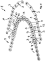
- the jaw implant 1 shown here has an internal first perforated bar 2 that is approximately U-shaped.
- the perforated bar 2 has spaced-apart attachment holes 3 that are intended for mounting the jaw implant 1 on the patient's jawbone and, in addition to or instead of, attaching a denture.
- Cross-sectional weakenings 4 are provided at the intervals between adjacent attachment holes 3. These weakenings facilitate deformation and shape adaptation of the internal first perforated bar 2 in accordance with the external bone structure and are also intended for cutting this perforated bar 2 to length.
- the jaw implant 1 can be mass-produced or even industrially in large quantities and subsequently adapted to the individual circumstances in the area of the jaw 5 to be treated, even during a single treatment appointment.
- the internal first perforated strip 2 has, in a partial area 8 arranged at a distance from the free ends 6, 7 of this perforated strip 2, in the area of each fastening hole 3 having an internal thread for fastening a dental prosthesis, a cross-sectional thickening 9 which increases the longitudinal extent of this fastening hole 3.
- the inner first perforated strip 2 is connected on both sides via connecting webs 10 to an outer second perforated strip 11, 12.
- the first perforated strip 2 and the second perforated strips 11, 12 have a link-chain-shaped outer contour, each with a rounded shape in the area of each fastening hole 3 and a waist-shaped indentation designed as a cross-sectional weakening 4 between adjacent fastening holes 3.
- cross-sectional thickenings 9 have a non-circular outer contour, so that a dental prosthesis screwed onto these cross-sectional thickenings 9 can be easily mounted thereon in a rotationally fixed manner.
- the cross-sectional thickenings 9 are each designed as a double-sided material thickening of the inner first perforated strip 2, which material thickenings have a preferably circular segment-shaped outer contour with outer lines or chords arranged on opposite sides towards adjacent cross-sectional thickenings.
- first perforated strip 2 and/or the second perforated strips 11, 12 have a reduced cross-section in a central region of the longitudinal extension and can have a thickened or enlarged cross-section towards their free end regions. Due to such a dogbone-shaped cross-section, the inner first perforated strip 2 and/or the outer second perforated strip(s) 11, 12 only rest on the jaw 5 with the outer edge regions of this cross-sectional shape, whereby parts of the jaw 5 below the perforated strips 2, 11, 12 are subjected to less stress, while still having sufficient blood flow.
- fastening holes 3 provided at the free end regions 6, 7 of the first perforated strip 2 and intended for fastening the perforated strip 2 to the jaw 5 also have an internal thread. Furthermore, such an internal thread is also provided in each of the fastening holes 3 provided on one of the second perforated strips 11, 12.
- the second perforated strips 11, 12 are adapted to the shape of the U-shaped inner first perforated strip 2 and also have a rounded shape in their longitudinal extension.
- the jaw implant 1 is designed to be cut to length and deformable in the region of its connecting bars 10.
- the jaw implant 1 in the area its connecting webs 10 are designed to be deformable in such a way that the inner first perforated strip 2 can be mounted on the jaw ridge, while the outer second perforated strip(s) 11, 12 can be fastened to the outer flanks of the jaw 5.
- fastening holes 3 provided in the area of such cross-sectional thickenings 9 can also be used to fasten the inner first perforated strip 2 to the ridge of the jaw 5, if corresponding fastening screws are screwed into the jawbone through these fastening holes 3.
- the prefabricated jaw implant 1 shown can also be shortened along its longitudinal central axis in such a way that the half of the inner first perforated bar 2 can be attached to the corresponding half of the alveolar ridge of the jaw 5 to be treated, while the second perforated bar 11, which is connected to this half of the perforated bar via the connecting webs 10, is screwed tightly to the adjacent outer flank of the jaw 5.
- the fastening holes 3 provided in the area of the cross-sectional thickenings 9 can carry the required dentures.
- the inner first perforated strip 2 of the Figures 1 to 3 The prefabricated jaw implant 1 shown can also be separated in order to use a corresponding section of this internal first perforated strip 2 for mounting dental prostheses. At least some of the fastening holes 3 provided in the area of the cross-sectional thickenings 9 can be penetrated by fastening screws (not shown in detail), which are anchored in the jawbone with their threaded shaft projecting beyond the corresponding section of the perforated strip 2.
- Figure 9 It has been shown that the Figures 7 and 8 Separated sections of the inner first perforated strip can also be used to permanently bridge a gap in the dental strip and, if necessary, in the underlying jawbone.
- the link-chain-shaped outer contour of the perforated strips 2, 11, 12 and the waist-shaped cross-sectional weakenings 4 provided between the fastening holes 3 form constrictions at which the perforated strips 2, 11, 12 can be severed, cut to length and/or deformed. Sections of the prefabricated jaw implant 1 can be used as a sufficiently stable retroplate in tooth-bearing areas.
Landscapes
- Health & Medical Sciences (AREA)
- Oral & Maxillofacial Surgery (AREA)
- Orthopedic Medicine & Surgery (AREA)
- Dentistry (AREA)
- Epidemiology (AREA)
- Life Sciences & Earth Sciences (AREA)
- Animal Behavior & Ethology (AREA)
- General Health & Medical Sciences (AREA)
- Public Health (AREA)
- Veterinary Medicine (AREA)
- Engineering & Computer Science (AREA)
- Ceramic Engineering (AREA)
- Dental Prosthetics (AREA)
Applications Claiming Priority (2)
| Application Number | Priority Date | Filing Date | Title |
|---|---|---|---|
| DE102020130333.5A DE102020130333A1 (de) | 2020-11-17 | 2020-11-17 | Kieferimplantat |
| PCT/EP2021/081713 WO2022106364A1 (de) | 2020-11-17 | 2021-11-15 | Kieferimplantat |
Publications (3)
| Publication Number | Publication Date |
|---|---|
| EP4247294A1 EP4247294A1 (de) | 2023-09-27 |
| EP4247294C0 EP4247294C0 (de) | 2025-06-18 |
| EP4247294B1 true EP4247294B1 (de) | 2025-06-18 |
Family
ID=79170986
Family Applications (1)
| Application Number | Title | Priority Date | Filing Date |
|---|---|---|---|
| EP21835158.3A Active EP4247294B1 (de) | 2020-11-17 | 2021-11-15 | Kieferimplantat |
Country Status (7)
| Country | Link |
|---|---|
| US (1) | US20240016583A1 (pl) |
| EP (1) | EP4247294B1 (pl) |
| DE (1) | DE102020130333A1 (pl) |
| ES (1) | ES3036688T3 (pl) |
| HU (1) | HUE072857T2 (pl) |
| PL (1) | PL4247294T3 (pl) |
| WO (1) | WO2022106364A1 (pl) |
Citations (1)
| Publication number | Priority date | Publication date | Assignee | Title |
|---|---|---|---|---|
| WO2016198935A1 (en) * | 2015-06-08 | 2016-12-15 | Cadskills Bvba | Subperiosteal jaw implant |
Family Cites Families (24)
| Publication number | Priority date | Publication date | Assignee | Title |
|---|---|---|---|---|
| DE1075791B (de) * | 1956-03-09 | 1960-02-18 | med habil Otto Henningsen und Dr med dent Horst Kumme Rom Dr | Trag- und Stützgerüst fur Zahnproesen |
| DE8611346U1 (de) * | 1986-04-24 | 1990-02-08 | Riess, Guido W., Prof. Dr., 8000 München | Implantat |
| US4713004A (en) * | 1986-09-04 | 1987-12-15 | Vent Plant Corporation | Submergible screw-type dental implant and method of utilization |
| US5052930A (en) * | 1989-11-22 | 1991-10-01 | Lodde Jean Pierre | Dental implant and method of implantation |
| US5133662A (en) * | 1991-09-03 | 1992-07-28 | Metcalfe Edwin R | Tooth implant device |
| US5419701A (en) * | 1991-12-19 | 1995-05-30 | Propper; Robert H. | Endosteal dental implant with supplementary stabilizer |
| US5306150A (en) * | 1992-08-04 | 1994-04-26 | Gittleman Neal B | Dental ramus implant |
| US5769637A (en) * | 1996-05-22 | 1998-06-23 | Sofamor Danek Properties, Inc. | Dental implant and alveolar process augmentation structures and method of installation |
| DE19803628A1 (de) * | 1997-07-09 | 1999-01-14 | Holger K Dr Essiger | Vorrichtung zur Regeneration, Reparatur und Modellation von menschlichen und tierischen Knochen, insb. im Zahnkieferbereich |
| IT1301941B1 (it) * | 1998-07-27 | 2000-07-20 | Nomet Man Services B V | Elemento modulare di impianto per protesi dentarie |
| DE29909025U1 (de) * | 1999-05-25 | 1999-11-04 | Lipat Consulting Ag, Basel | Osteosynthetische Knochenplatte |
| DE20121531U1 (de) * | 2000-06-09 | 2003-03-13 | Engelke, Wilfried, Prof. Dr.Dr.med., 37130 Gleichen | Subgingivale Verbindungsvorrichtung |
| US20030232308A1 (en) * | 2002-06-14 | 2003-12-18 | Simmons Earl Wayne | Method and apparatus for dental implants |
| DE502006006702D1 (de) * | 2005-03-24 | 2010-05-27 | Medartis Ag | Knochenplatte |
| US20080081315A1 (en) * | 2006-09-28 | 2008-04-03 | Kim Samuel S | Dr. Seoung Ho Lee's augmentation plates for stabilizing dental implant fixtures |
| US9107712B2 (en) * | 2008-09-15 | 2015-08-18 | Biomet C.V. | Bone plate system for hand fractures and other small bones |
| KR101139962B1 (ko) * | 2009-12-24 | 2012-04-30 | 오스템임플란트 주식회사 | 플레이트를 가진 치과용 임플란트 |
| CA2903821A1 (en) * | 2013-03-04 | 2014-09-12 | EdMiDent, LLC | Intraosseous dental implant support mechanism |
| AU2013393570A1 (en) * | 2013-07-01 | 2016-01-21 | Manuel Angel MARTINEZ NAVARRO | System for securing a dental prosthesis |
| US10149745B2 (en) * | 2015-06-18 | 2018-12-11 | Panthera Dental Inc. | Method and system for generating a model of a subperiosteal dental implant device and customized implant head |
| DE102015122800B3 (de) | 2015-12-23 | 2017-05-11 | Karl Leibinger Medizintechnik Gmbh & Co. Kg | Knochenstrukturangepasst ausgeformtes Implantat mit Sockel und zugehöriges Fertigungsverfahren |
| CN106175903B (zh) * | 2016-06-29 | 2019-06-14 | 浙江工业大学 | 用于修复骨折下颌骨的三维固定板制作方法及三维固定板 |
| US12089882B2 (en) * | 2019-04-30 | 2024-09-17 | Fusion Innovations, Llc | Method and system for assembling a structure to secure to opposite sides of a fracture in a bone of a subject |
| US20220015871A1 (en) * | 2020-07-17 | 2022-01-20 | OMX Solutions Pty. Ltd. | Annular-shaped subperiosteal jaw implant |
-
2020
- 2020-11-17 DE DE102020130333.5A patent/DE102020130333A1/de active Pending
-
2021
- 2021-11-15 HU HUE21835158A patent/HUE072857T2/hu unknown
- 2021-11-15 PL PL21835158.3T patent/PL4247294T3/pl unknown
- 2021-11-15 ES ES21835158T patent/ES3036688T3/es active Active
- 2021-11-15 EP EP21835158.3A patent/EP4247294B1/de active Active
- 2021-11-15 WO PCT/EP2021/081713 patent/WO2022106364A1/de not_active Ceased
- 2021-11-15 US US18/037,115 patent/US20240016583A1/en active Pending
Patent Citations (1)
| Publication number | Priority date | Publication date | Assignee | Title |
|---|---|---|---|---|
| WO2016198935A1 (en) * | 2015-06-08 | 2016-12-15 | Cadskills Bvba | Subperiosteal jaw implant |
Also Published As
| Publication number | Publication date |
|---|---|
| EP4247294A1 (de) | 2023-09-27 |
| EP4247294C0 (de) | 2025-06-18 |
| ES3036688T3 (en) | 2025-09-23 |
| WO2022106364A1 (de) | 2022-05-27 |
| PL4247294T3 (pl) | 2025-09-08 |
| DE102020130333A1 (de) | 2022-05-19 |
| HUE072857T2 (hu) | 2025-12-28 |
| US20240016583A1 (en) | 2024-01-18 |
Similar Documents
| Publication | Publication Date | Title |
|---|---|---|
| EP2299920B1 (de) | Vorrichtung zur osteosynthese sowie zur fixierung und stabilisierung von röhrenknochen | |
| EP1309287B1 (de) | Zahnschiene | |
| EP1404247B1 (de) | Kieferorthopädisches implantatsystem zur zahnmobilisierung | |
| DE102015122800B3 (de) | Knochenstrukturangepasst ausgeformtes Implantat mit Sockel und zugehöriges Fertigungsverfahren | |
| EP3393376B1 (de) | Implantat zur knochenverstärkung mit bohrvektorvorgabeloch und umgriffsplatte für kieferersatz sowie implantatherstellverfahren | |
| WO2018033608A1 (de) | Dental-prothetiksystem und prothetische konstruktion zur verwendung mit einem in den kieferknochen eines patienten inserierten dentalimplantat | |
| EP3449869B1 (de) | Implantat-teil | |
| EP3148461B1 (de) | Fixierungsvorrichtung für knochenfrakturen | |
| DE102006051082A1 (de) | Kieferorthopädische Verankerungsschraube | |
| DE68919698T2 (de) | Mandibulare knochenbasisplatte. | |
| EP2680769B1 (de) | Spannelement zum fixieren einer knochenfraktur sowie selbiges aufweisende modulare fixierungsvorrichtung und verfahren zur herstellung hierfür | |
| DE29820487U1 (de) | Laterales Kieferimplantat | |
| DE19915395B4 (de) | Knochenimplantatvorrichtung zur Gewebegenerierung mittels Knochenersatzmaterialien sowie Verfahren zur Herstellung der Knochenimplantatvorrichtung | |
| EP4247294A1 (de) | Kieferimplantat | |
| DE102020130327A1 (de) | Kieferimplantat | |
| DE10356920B4 (de) | In einen menschlichen Kiefer endostal einschraubbares Dentalimplantat zur Aufnahme und Fixierung eines Zahnersatzes | |
| EP1527749A2 (de) | In einen menschlichen Kiefer endostal einschraubbares Dentalimplantat zur Aufnahme und Fixierung eines Zahnersatzes | |
| DE1075791B (de) | Trag- und Stützgerüst fur Zahnproesen | |
| EP1457165B1 (de) | Dentalimplantat | |
| DE29908207U1 (de) | Kieferimplantat | |
| AT504473A4 (de) | Zahnimplantatträger | |
| DE202013011239U1 (de) | Dentalimplantat und auf dem Implantat basierende provisorische Konstruktion | |
| DE202009007043U1 (de) | Ein in originalzahngetreuer Form angefertigter Einzelzahnimplantat mit einem Gewebeintegrations-, und Befestigungsmechanismus | |
| DE2522941A1 (de) | Oralimplantat | |
| DE102022130314A1 (de) | Kieferprothese und Verstärkungseinlage für eine Kieferprothese |
Legal Events
| Date | Code | Title | Description |
|---|---|---|---|
| STAA | Information on the status of an ep patent application or granted ep patent |
Free format text: STATUS: UNKNOWN |
|
| STAA | Information on the status of an ep patent application or granted ep patent |
Free format text: STATUS: THE INTERNATIONAL PUBLICATION HAS BEEN MADE |
|
| PUAI | Public reference made under article 153(3) epc to a published international application that has entered the european phase |
Free format text: ORIGINAL CODE: 0009012 |
|
| STAA | Information on the status of an ep patent application or granted ep patent |
Free format text: STATUS: REQUEST FOR EXAMINATION WAS MADE |
|
| 17P | Request for examination filed |
Effective date: 20230619 |
|
| AK | Designated contracting states |
Kind code of ref document: A1 Designated state(s): AL AT BE BG CH CY CZ DE DK EE ES FI FR GB GR HR HU IE IS IT LI LT LU LV MC MK MT NL NO PL PT RO RS SE SI SK SM TR |
|
| DAV | Request for validation of the european patent (deleted) | ||
| DAX | Request for extension of the european patent (deleted) | ||
| STAA | Information on the status of an ep patent application or granted ep patent |
Free format text: STATUS: EXAMINATION IS IN PROGRESS |
|
| 17Q | First examination report despatched |
Effective date: 20240807 |
|
| GRAP | Despatch of communication of intention to grant a patent |
Free format text: ORIGINAL CODE: EPIDOSNIGR1 |
|
| STAA | Information on the status of an ep patent application or granted ep patent |
Free format text: STATUS: GRANT OF PATENT IS INTENDED |
|
| INTG | Intention to grant announced |
Effective date: 20250127 |
|
| GRAS | Grant fee paid |
Free format text: ORIGINAL CODE: EPIDOSNIGR3 |
|
| GRAA | (expected) grant |
Free format text: ORIGINAL CODE: 0009210 |
|
| STAA | Information on the status of an ep patent application or granted ep patent |
Free format text: STATUS: THE PATENT HAS BEEN GRANTED |
|
| AK | Designated contracting states |
Kind code of ref document: B1 Designated state(s): AL AT BE BG CH CY CZ DE DK EE ES FI FR GB GR HR HU IE IS IT LI LT LU LV MC MK MT NL NO PL PT RO RS SE SI SK SM TR |
|
| REG | Reference to a national code |
Ref country code: GB Ref legal event code: FG4D Free format text: NOT ENGLISH |
|
| REG | Reference to a national code |
Ref country code: CH Ref legal event code: EP |
|
| REG | Reference to a national code |
Ref country code: DE Ref legal event code: R096 Ref document number: 502021007805 Country of ref document: DE |
|
| REG | Reference to a national code |
Ref country code: CH Ref legal event code: EP |
|
| REG | Reference to a national code |
Ref country code: IE Ref legal event code: FG4D Free format text: LANGUAGE OF EP DOCUMENT: GERMAN |
|
| U01 | Request for unitary effect filed |
Effective date: 20250709 |
|
| U07 | Unitary effect registered |
Designated state(s): AT BE BG DE DK EE FI FR IT LT LU LV MT NL PT RO SE SI Effective date: 20250715 |
|
| REG | Reference to a national code |
Ref country code: ES Ref legal event code: FG2A Ref document number: 3036688 Country of ref document: ES Kind code of ref document: T3 Effective date: 20250923 |
|
| PG25 | Lapsed in a contracting state [announced via postgrant information from national office to epo] |
Ref country code: GR Free format text: LAPSE BECAUSE OF FAILURE TO SUBMIT A TRANSLATION OF THE DESCRIPTION OR TO PAY THE FEE WITHIN THE PRESCRIBED TIME-LIMIT Effective date: 20250919 |
|
| PG25 | Lapsed in a contracting state [announced via postgrant information from national office to epo] |
Ref country code: HR Free format text: LAPSE BECAUSE OF FAILURE TO SUBMIT A TRANSLATION OF THE DESCRIPTION OR TO PAY THE FEE WITHIN THE PRESCRIBED TIME-LIMIT Effective date: 20250618 |
|
| PG25 | Lapsed in a contracting state [announced via postgrant information from national office to epo] |
Ref country code: RS Free format text: LAPSE BECAUSE OF FAILURE TO SUBMIT A TRANSLATION OF THE DESCRIPTION OR TO PAY THE FEE WITHIN THE PRESCRIBED TIME-LIMIT Effective date: 20250918 |
|
| REG | Reference to a national code |
Ref country code: CH Ref legal event code: U11 Free format text: ST27 STATUS EVENT CODE: U-0-0-U10-U11 (AS PROVIDED BY THE NATIONAL OFFICE) Effective date: 20251201 |
|
| U20 | Renewal fee for the european patent with unitary effect paid |
Year of fee payment: 5 Effective date: 20251028 |
|
| PGFP | Annual fee paid to national office [announced via postgrant information from national office to epo] |
Ref country code: HU Payment date: 20251111 Year of fee payment: 5 |
|
| REG | Reference to a national code |
Ref country code: HU Ref legal event code: AG4A Ref document number: E072857 Country of ref document: HU |
|
| PG25 | Lapsed in a contracting state [announced via postgrant information from national office to epo] |
Ref country code: IS Free format text: LAPSE BECAUSE OF FAILURE TO SUBMIT A TRANSLATION OF THE DESCRIPTION OR TO PAY THE FEE WITHIN THE PRESCRIBED TIME-LIMIT Effective date: 20251018 |
|
| PGFP | Annual fee paid to national office [announced via postgrant information from national office to epo] |
Ref country code: GB Payment date: 20251120 Year of fee payment: 5 |
|
| PGFP | Annual fee paid to national office [announced via postgrant information from national office to epo] |
Ref country code: NO Payment date: 20251118 Year of fee payment: 5 |
|
| PG25 | Lapsed in a contracting state [announced via postgrant information from national office to epo] |
Ref country code: SM Free format text: LAPSE BECAUSE OF FAILURE TO SUBMIT A TRANSLATION OF THE DESCRIPTION OR TO PAY THE FEE WITHIN THE PRESCRIBED TIME-LIMIT Effective date: 20250618 |
|
| PGFP | Annual fee paid to national office [announced via postgrant information from national office to epo] |
Ref country code: TR Payment date: 20251112 Year of fee payment: 5 |
|
| PGFP | Annual fee paid to national office [announced via postgrant information from national office to epo] |
Ref country code: CH Payment date: 20251201 Year of fee payment: 5 |
|
| PG25 | Lapsed in a contracting state [announced via postgrant information from national office to epo] |
Ref country code: CZ Free format text: LAPSE BECAUSE OF FAILURE TO SUBMIT A TRANSLATION OF THE DESCRIPTION OR TO PAY THE FEE WITHIN THE PRESCRIBED TIME-LIMIT Effective date: 20250618 |
|
| PGFP | Annual fee paid to national office [announced via postgrant information from national office to epo] |
Ref country code: IE Payment date: 20251120 Year of fee payment: 5 |
|
| PGFP | Annual fee paid to national office [announced via postgrant information from national office to epo] |
Ref country code: PL Payment date: 20251107 Year of fee payment: 5 |
|
| PG25 | Lapsed in a contracting state [announced via postgrant information from national office to epo] |
Ref country code: SK Free format text: LAPSE BECAUSE OF FAILURE TO SUBMIT A TRANSLATION OF THE DESCRIPTION OR TO PAY THE FEE WITHIN THE PRESCRIBED TIME-LIMIT Effective date: 20250618 |
|
| PGFP | Annual fee paid to national office [announced via postgrant information from national office to epo] |
Ref country code: ES Payment date: 20251216 Year of fee payment: 5 |
|
| PLBE | No opposition filed within time limit |
Free format text: ORIGINAL CODE: 0009261 |
|
| STAA | Information on the status of an ep patent application or granted ep patent |
Free format text: STATUS: NO OPPOSITION FILED WITHIN TIME LIMIT |
|
| REG | Reference to a national code |
Ref country code: CH Ref legal event code: L10 Free format text: ST27 STATUS EVENT CODE: U-0-0-L10-L00 (AS PROVIDED BY THE NATIONAL OFFICE) Effective date: 20260430 |