EP4247600B1 - Method, cutting device and apparatus particularly for manufacturing pouches with rounded corners - Google Patents
Method, cutting device and apparatus particularly for manufacturing pouches with rounded corners Download PDFInfo
- Publication number
- EP4247600B1 EP4247600B1 EP21802775.3A EP21802775A EP4247600B1 EP 4247600 B1 EP4247600 B1 EP 4247600B1 EP 21802775 A EP21802775 A EP 21802775A EP 4247600 B1 EP4247600 B1 EP 4247600B1
- Authority
- EP
- European Patent Office
- Prior art keywords
- cutting
- ribbon
- blade
- along
- stroke
- Prior art date
- Legal status (The legal status is an assumption and is not a legal conclusion. Google has not performed a legal analysis and makes no representation as to the accuracy of the status listed.)
- Active
Links
Images




Classifications
-
- B—PERFORMING OPERATIONS; TRANSPORTING
- B31—MAKING ARTICLES OF PAPER, CARDBOARD OR MATERIAL WORKED IN A MANNER ANALOGOUS TO PAPER; WORKING PAPER, CARDBOARD OR MATERIAL WORKED IN A MANNER ANALOGOUS TO PAPER
- B31B—MAKING CONTAINERS OF PAPER, CARDBOARD OR MATERIAL WORKED IN A MANNER ANALOGOUS TO PAPER
- B31B70/00—Making flexible containers, e.g. envelopes or bags
- B31B70/14—Cutting, e.g. perforating, punching, slitting or trimming
- B31B70/148—Cutting-out portions from the sides of webs or sheets
-
- B—PERFORMING OPERATIONS; TRANSPORTING
- B26—HAND CUTTING TOOLS; CUTTING; SEVERING
- B26D—CUTTING; DETAILS COMMON TO MACHINES FOR PERFORATING, PUNCHING, CUTTING-OUT, STAMPING-OUT OR SEVERING
- B26D1/00—Cutting through work characterised by the nature or movement of the cutting member or particular materials not otherwise provided for; Apparatus or machines therefor; Cutting members therefor
- B26D1/01—Cutting through work characterised by the nature or movement of the cutting member or particular materials not otherwise provided for; Apparatus or machines therefor; Cutting members therefor involving a cutting member which does not travel with the work
- B26D1/04—Cutting through work characterised by the nature or movement of the cutting member or particular materials not otherwise provided for; Apparatus or machines therefor; Cutting members therefor involving a cutting member which does not travel with the work having a linearly-movable cutting member
- B26D1/06—Cutting through work characterised by the nature or movement of the cutting member or particular materials not otherwise provided for; Apparatus or machines therefor; Cutting members therefor involving a cutting member which does not travel with the work having a linearly-movable cutting member wherein the cutting member reciprocates
- B26D1/08—Cutting through work characterised by the nature or movement of the cutting member or particular materials not otherwise provided for; Apparatus or machines therefor; Cutting members therefor involving a cutting member which does not travel with the work having a linearly-movable cutting member wherein the cutting member reciprocates of the guillotine type
- B26D1/085—Cutting through work characterised by the nature or movement of the cutting member or particular materials not otherwise provided for; Apparatus or machines therefor; Cutting members therefor involving a cutting member which does not travel with the work having a linearly-movable cutting member wherein the cutting member reciprocates of the guillotine type for thin material, e.g. for sheets, strips or the like
-
- B—PERFORMING OPERATIONS; TRANSPORTING
- B26—HAND CUTTING TOOLS; CUTTING; SEVERING
- B26D—CUTTING; DETAILS COMMON TO MACHINES FOR PERFORATING, PUNCHING, CUTTING-OUT, STAMPING-OUT OR SEVERING
- B26D5/00—Arrangements for operating and controlling machines or devices for cutting, cutting-out, stamping-out, punching, perforating, or severing by means other than cutting
- B26D5/02—Means for moving the cutting member into its operative position for cutting
-
- B—PERFORMING OPERATIONS; TRANSPORTING
- B31—MAKING ARTICLES OF PAPER, CARDBOARD OR MATERIAL WORKED IN A MANNER ANALOGOUS TO PAPER; WORKING PAPER, CARDBOARD OR MATERIAL WORKED IN A MANNER ANALOGOUS TO PAPER
- B31B—MAKING CONTAINERS OF PAPER, CARDBOARD OR MATERIAL WORKED IN A MANNER ANALOGOUS TO PAPER
- B31B2155/00—Flexible containers made from webs
-
- B—PERFORMING OPERATIONS; TRANSPORTING
- B31—MAKING ARTICLES OF PAPER, CARDBOARD OR MATERIAL WORKED IN A MANNER ANALOGOUS TO PAPER; WORKING PAPER, CARDBOARD OR MATERIAL WORKED IN A MANNER ANALOGOUS TO PAPER
- B31B—MAKING CONTAINERS OF PAPER, CARDBOARD OR MATERIAL WORKED IN A MANNER ANALOGOUS TO PAPER
- B31B2160/00—Shape of flexible containers
- B31B2160/10—Shape of flexible containers rectangular and flat, i.e. without structural provision for thickness of contents
- B31B2160/106—Shape of flexible containers rectangular and flat, i.e. without structural provision for thickness of contents obtained from sheets cut from larger sheets or webs before finishing the bag forming operations
Definitions
- the present invention relates to a method, a cutting device and an apparatus particularly for manufacturing pouches with rounded corners for flexible containers such as Doypacks ® and the like.
- the pouches are provided starting from at least two sheets (or from a single sheet folded onto itself) which are optionally in turn composed of multiple layers and of which at least one sheet or layer can comprise or be constituted by materials such as aluminum, PE, PP or other thermoplastic materials.
- the sheets which are unwound from respective reels, are superimposed (or, in the case of a single sheet, folded in half along the longitudinal centerline) and then mutually coupled at joining strips, which are typically transverse and longitudinal in order to form a sort of joining grid.
- the sheets Downstream of this coupling operation, the sheets are rendered integral with each other at the joining strips, thus forming a ribbon inside which respective pockets are formed in the regions surrounded, i.e., not affected, by the joining strips.
- the ribbon can be subsequently conveniently cut longitudinally in order to form a plurality of parallel ribbons and in any case at the end is cut transversely in the form of final pouches.
- the die-cutting tool is usually circular or quadrangular with preferably concave sides (for example, a shape similar to an astroid) and is such to leave, on the edges of the longitudinally cut ribbon, recesses which, in the case of quadrangular shapes with concave sides, are substantially cusp-shaped.
- one of the two pouches obtained by the transverse cut will have, near the corners, a burr which corresponds to the initial portion of the rise from the tip of the original cusp toward the pocket originally adjacent to that of the pouch subsequently obtained with the transverse cut.
- the aim of the present invention is to provide a method for manufacturing pouches for flexible containers such as stand-up pouches (Doypacks ® ) and the like, as well as a cutting device and a corresponding apparatus, that are capable of improving the prior art in one or more of the aspects mentioned above.
- Doypacks ® stand-up pouches
- the aim of the present invention is to provide a method for manufacturing pouches for flexible containers such as stand-up pouches (Doypacks ® ) and the like, as well as a cutting device and a corresponding apparatus, that are capable of improving the prior art in one or more of the aspects mentioned above.
- an object of the invention is to avoid the forming of burrs as a consequence of the transverse cutting of a ribbon.
- an object of the invention is to compensate any inaccuracies of the transverse cutting of a ribbon, or of multiple ribbons arranged side by side, at recesses arranged along the lateral edges of the ribbon or ribbons and/or at through die-cut portions arranged along the ribbon or ribbons.
- Another object of the invention is to allow its application to existing apparatuses for manufacturing pouches for flexible containers such as Doypacks ® and the like.
- an object of the present invention is to overcome the drawbacks of the background art in a manner that is alternative to any existing solutions.
- Not least object of the invention is to provide a method, a cutting device and a corresponding apparatus for manufacturing pouches which are highly reliable, relatively easy to provide and at competitive costs.
- an apparatus for manufacturing pouches of flexible containers with rounded corners such as Doypacks ® and the like, according to the invention, is generally designated by the reference numeral 10 and comprises means 8A, 8B for unwinding at least one sheet in reel form, preferably two sheets 5A, 5B, from respective reels 7A, 7B, as in the case shown in Figure 1 .
- the sheets 5A and 5B can each be formed by a plurality of layers, each constituted by or comprising known materials used in the field of packaging to form so-called pouches or Doypacks ® , for example for fruit purees, drinks or powders. These materials can be selected from the group comprising aluminum, PE, PET, PP, OPP and/or other thermoplastic materials.
- a layer made of thermoplastic material preferably polyethylene (PE)
- PE polyethylene
- An example of sheet 5A and/or 5B might be made of at least two layers of a respective thermoplastic material, for example PE and/or PET (polyethylene terephthalate), optionally interspersed with other materials, for example an aluminum layer or an aluminum layer and a nylon layer.
- sheets 5A and 5B particularly adapted to be processed according to the teachings of the invention provide for one among these sheets:
- the unwinding means may comprise, besides the cylinders for supporting the rotation of the reels 7A, 7B, also tensioning rollers, which are optionally mutually movable, and overlap cylinders 9 adapted to superimpose the two sheets 5A and 5B substantially in register.
- the unwinding means can comprise, in a per se known manner, also a folding wedge in order to fold longitudinally in half the single sheet so that the two halves can be subsequently superimposed on each other by the overlap means.
- the apparatus 10 Downstream of the unwinding means with respect to the unwinding direction, the apparatus 10 comprises coupling means 4, 4B for mutually fixing the two sheets 5A and 5B one on the other (or, in the example of embodiment not shown, the two halves of the single sheet folded onto itself) along at least transverse joining strips 51.
- the strips 51 are substantially rectilinear and mutually parallel along at least one transverse direction which is preferably at right angles to a substantially rectilinear direction D of advancement of the sheets 5A and 5B, also referenced herein as feeding direction D.
- the coupling can be obtained by heat-sealing, taping and/or gluing at least along transverse bands of the superimposed sheets, in order to mutually anchor the sheets, forming the joining strips 51.
- a ribbon 5 is thus obtained which is made to advance in step mode in the feeding direction D.
- the advancement step is preferably equal to, or a multiple of, the distance between two pockets 53 arranged side by side in said longitudinal direction of the ribbon 5.
- the advancement means can comprise a traction station 2 arranged downstream of the coupling means 4 and optionally 4B and said station 2 can be provided with mutually opposite traction rollers which pull in the feeding direction D the ribbon 5 interposed between them.
- the traction station 2 can comprise other per se known stepwise traction solutions, for example a conveyor with cleats or movable clamps which, with a movement that is substantially parallel to the feeding direction D, retain temporarily the external edges of the ribbon 5 in order to make it advance by one or more steps in the feeding direction D, to then release it, return and repeat the operation.
- a conveyor with cleats or movable clamps which, with a movement that is substantially parallel to the feeding direction D, retain temporarily the external edges of the ribbon 5 in order to make it advance by one or more steps in the feeding direction D, to then release it, return and repeat the operation.
- the two superimposed sheets 5A and 5B are joined in a similar manner also at one or more longitudinal joining strips 52, which are substantially rectilinear and parallel to the advancement direction D of the sheets 5A, 5B and form a joining grid together with the transverse joining strips 51.
- the coupling means 4B for obtaining longitudinal joining strips 52 can be separate with respect to the coupling means in order to obtain the transverse joining strips 51, but they operate in a similar manner, for example by heat-sealing, taping and/or gluing.
- the coupling means 4, 4B, as well as the coupling by virtue of joining strips or grids between superimposed sheets for manufacturing pouches, are per se known in the field.
- the apparatus 10 furthermore provides advantageously a cooling station 4A downstream of the coupling means with respect to the feeding direction D, in order to cool the ribbon 5 at least at the joining strips 51 and optionally 52.
- the cooling station 4A can be interposed between the coupling means 4 and 4B.
- the joining strips 51 and optionally 52 are adapted to form, evenly arranged side by side along at least the longitudinal direction of the ribbon 5, a plurality of pockets 53 in the regions not affected by the joining strips 51 or 52, i.e., in the regions surrounded by the joining strips 51 and 52.
- the pockets 53 are such as to have an open side 54, for example in the regions not affected, or affected only partially, by the longitudinal joining strips 52.
- the transverse joining strips 51 form the sides of the pouches 6, while the longitudinal joining strips 52 will form the bottoms of the pouches 6.
- the apparatus 10 can also comprise longitudinal cutting means 3, of a per se known type, which are adapted to cut the ribbon 5 along the longitudinal joining strips 52 and to consequently form a plurality of substantially parallel ribbons.
- longitudinal cutting means 3 of a per se known type, which are adapted to cut the ribbon 5 along the longitudinal joining strips 52 and to consequently form a plurality of substantially parallel ribbons.
- ribbon 5" will be used also with reference to the set of these parallel ribbons obtained from the ribbon 5 with said optional longitudinal cut.
- the apparatus 10 comprises, moreover, die cutting means 4C, of a per se known type, which are configured to die-cut from a part of the ribbon 5, along the longitudinal edges of the ribbon 5 and/or at the intersections between the longitudinal joining strips 52 and the transverse one 51, portions adapted to form preferably cusp-shaped recesses 55-56.
- the die cutting means can comprise one or more cutting dies the cutting edge of which is quadrangular or diamond-shaped, with preferably concave sides (for example, substantially hypocycloidal or astroid-like) with the diagonals oriented like the joining strips 51 and 52.
- Figure 7 shows an astroid-shaped opening 57 which is obtained with the die cutting of the ribbon 5 at an intersection between the joining strips 51 and 52 and which forms the cusp-shaped recesses toward the regions affected by the cutting operation.
- the apparatus 10 downstream of the devices described above the apparatus 10 comprises a transverse cutting device 1 having a feeding inlet 11 adapted to receive from the feeding means 2, along the substantially rectilinear feeding direction D, the ribbon 5, optionally cut longitudinally into a plurality of parallel ribbons by the longitudinal cutting device 3.
- the feeding inlet 11 can be essentially a slit adapted to contain the ribbon 5 against movements at right angles to the plane of arrangement P and is preferably configured to form, frontally toward the blade 12, an abutment surface for the blade 12, so that the edges of the slit that are directed toward the blade act as a counter-blade in order to perform the transverse cut.
- the transverse cutting direction C1 or C2 of the device 1 is substantially rectilinear and at right angles to the feeding direction D.
- the rectilinear cutting directions C1 and C2 define, together with the rectilinear feeding direction D, a geometric plane of arrangement P of the ribbon, i.e., a substantially ideal plane on which the ribbon 5 lies during its advancement through the feeding inlet 11.
- the device 1 comprises at least one cutting blade 12 adapted to cut the ribbon 5 transversely to the feeding direction D, preferably at right angles to the direction D.
- the cutting blade 12 can be a single blade with a double cutting edge or, as in the case shown, can be a set of two cutters with a single cutting edge which are arranged side by side, so that the blade 12 has a first cutting edge and a second cutting edge along respective opposite edges.
- multiple transverse cutting blades 12, arranged side by side parallel to the feeding direction D of the ribbon 5, can be provided.
- One or more suction ports 16 connected to a pump, in order to extract the cutting chips, can be provided along the blade 12.
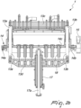
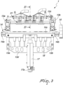
- the blade 12 is fixed on a blade holder 13, which in turn is mounted in a movable manner on a support 14.
- the blade holder 13 can comprise a transverse member 13c along which the blade 12 is fixed.
- the transverse member 13c is connected to first movement means adapted to translate the transverse member substantially transversely to the plane of arrangement P of the ribbon 5 and to the feeding direction D and with a reciprocating motion between a first position and a second position with respect to the plane of arrangement P of the ribbon 5, so that the blade 12 passes through said plane P in the transition between said two positions.
- cutting plane The geometric plane traced by the first or second cutting edge with said translation movement of the transverse member 13c with respect to the support 14 is termed herein "cutting plane”.
- the first position of the blade holder 13, and particularly of the transverse member 13c is such that the first cutting edge 12a of the cutting blade 12 faces the plane of arrangement P of the ribbon 5 and is preferably spaced from said plane.
- the second position of the blade holder 13 and particularly of the transverse member 13c is such that the second cutting edge 12b of the blade 12 faces the plane of arrangement P and is preferably spaced from said plane.
- the transverse member 13c can be supported by two uprights 13a-13b, which are associated with the support 14 so as to be able to extend or retract on command with respect to the support 14, along a plane that is substantially parallel to the cutting plane, i.e., transversely to the plane of arrangement P of the ribbon 5 and to the feeding direction D.
- the transverse member 13c and consequently the blade 12 can be moved between the first position and the second position with respect to the plane of arrangement P of the ribbon 5, passing through said plane during the transition between the two positions.
- the cutting device 1 also comprises the first movement means, for example in the form of an electric actuator, which are adapted to translate the blade holder 13 substantially at right angles to the plane of arrangement P of the ribbon 5 and to the feeding direction D, and between said first and second positions.
- the first movement means for example in the form of an electric actuator, which are adapted to translate the blade holder 13 substantially at right angles to the plane of arrangement P of the ribbon 5 and to the feeding direction D, and between said first and second positions.
- a linear motor 17 for example, it is possible to use as an electric actuator a linear motor 17, the movable stem 17a of which is fixed to a beam 14c (described hereinafter) and the stator of which is fixed to a lower transverse member 13d, which is parallel and connected to the transverse member 13c by means of said uprights 13a-13b, which slide through the beam 14c.
- one or more springs 18, for example of the magnetic type can optionally be fixed between the beam 14c and the lower transverse member 13d, in order to counteract the force of gravity, i.e. counterbalance the weight, and allow the linear motor 17 to apply only dynamic forces.
- the blade holder 13 can comprise one or more side-by-side pushers 31, for example electric or pneumatic actuators, which are adapted to push the pouches 6 downward.
- the support 14 of the blade holder 13 is movable substantially parallel to the advancement direction D of the ribbon 5.
- the support 14, in particular, translates with a reciprocating motion between a forward position and a retracted position along the feeding direction D and with respect to the ribbon 5 arriving at the feeding inlet 11.
- the stroke S of the support 14 along the direction D can be, for example, smaller than 5 mm.
- the support 14 can be provided so that said beam 14c extends substantially at right angles to the feeding direction D and substantially parallel to the plane of arrangement P of the ribbon 5 and the beam 14c is provided with a pair of sliders 14a, 14b arranged, for example, at the ends of the beam 14c and able to slide on respective guiding rails (not shown) parallel to the feeding direction D.
- the feeding inlet 11 can be rigidly coupled to the beam 14c.
- Second movement means 15 are provided in order to operate the sliding of the support 14 in the direction D with a forward/backward movement, particularly along said rails.
- the second movement means can be an electric actuator, for example a linear motor.
- the first and second movement means are synchronized, for example by means of a controller, so as to make the blade 12 follow cyclically a substantially closed path.
- the closed path of the blade can be obtained by virtue of the forward/backward movement of the support 14 which is alternated with the up/down movement of the blade holder 13, so that each complete movement between the first position and the second position of the blade holder 13 is alternated with a respective complete movement between the forward position and the retracted position of the support 14.
- controller of the movement means of the blade holder 13 and of its support 14 can be configured so that:
- the ribbon 5 is made to advance in step mode along the feeding direction D and, at the die cutting station 4C, the die cutting operation forms the cusp-shaped recesses 55, 56 with a constant pitch both along the external longitudinal edges 50 of the ribbon 5 and along any internal edges between the parallel ribbons that form as a consequence of the optional longitudinal cut.
- the transverse cut is performed from one longitudinal edge 50 to the other of the ribbon 5 and substantially at each one of the recesses 55-56.
- This transverse cut is performed by means of at least two strokes of the blade 12, between which a relative translation S is performed between the cutting plane (followed by the blade holder 13) and the ribbon 5 substantially along the feeding direction D. In this manner, any cutting defects of the first stroke in the region of the recess 55-56 are leveled with the second stroke.
- the relative translation is obtained by translating only the support 14 of the blade holder 13 between the forward position and the retracted position and vice versa, while the ribbon 5 remains stationary.
- said relative translation can be obtained with the advancement means 2, keeping the support 14 of the blade holder stationary.
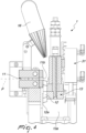
- the ribbon 5 is cut transversely along the direction C1 with the first cutting edge 12a. Cutting is performed with the support 14 in a retracted position, so that it occurs essentially downstream with respect to the line 58 of the cusps, i.e., of the ideal centerline between the pockets 53 of the ribbon 5.
- the pouch 6 or the pouches arranged side by side in a transverse direction of the ribbon 5 are made to fall by gravity and have a rounded edge 55 at the corners, since the cut has been performed, if not exactly at the centerline 58, downstream of said line with respect to the direction D.
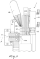
- the blade 12 reaches the second cutting position, shown in Figure 4 , which in the case shown is a lowered position.
- the support 14 is then moved by the amount S in the forward position, translating therefore toward the ribbon 5, and the second stroke of the blade is performed by means of the second cutting edge 12b and along the line C2. In this manner, the blade 12 levels any excess burr that results from the first cutting stroke and returns to the first position, shown in Figure 5 .
- the support 14 is finally made to retract into the retracted position, while the ribbon 5 is made to advance by an advancement step (substantially equal to the distance between two parallel lines of the cusps 58) so as to perform in the same manner the transverse cutting of the subsequent pouch 6 or set of pouches 6.
- the cutting method performs cyclically the following operations:
- the invention achieves the intended aim and objects, providing a method in which, if a first cutting stroke used normally in the field does not arrive exactly at the centerline 58 that joins the die-cut cusps on a ribbon, a second cutting stroke eliminates any cut-off burr that might protrude from the centerline 58 after the first cutting stroke.
- the materials used may be any according to the requirements and the state of the art.
Landscapes
- Life Sciences & Earth Sciences (AREA)
- Forests & Forestry (AREA)
- Engineering & Computer Science (AREA)
- Mechanical Engineering (AREA)
- Making Paper Articles (AREA)
- Perforating, Stamping-Out Or Severing By Means Other Than Cutting (AREA)
Applications Claiming Priority (2)
| Application Number | Priority Date | Filing Date | Title |
|---|---|---|---|
| IT102020000027989A IT202000027989A1 (it) | 2020-11-23 | 2020-11-23 | Procedimento, dispositivo di taglio e apparecchiatura particolarmente per la fabbricazione di buste ad angoli smussati. |
| PCT/EP2021/081431 WO2022106300A1 (en) | 2020-11-23 | 2021-11-11 | Method, cutting device and apparatus particularly for manufacturing pouches with rounded corners |
Publications (3)
| Publication Number | Publication Date |
|---|---|
| EP4247600A1 EP4247600A1 (en) | 2023-09-27 |
| EP4247600B1 true EP4247600B1 (en) | 2025-01-01 |
| EP4247600C0 EP4247600C0 (en) | 2025-01-01 |
Family
ID=74592439
Family Applications (1)
| Application Number | Title | Priority Date | Filing Date |
|---|---|---|---|
| EP21802775.3A Active EP4247600B1 (en) | 2020-11-23 | 2021-11-11 | Method, cutting device and apparatus particularly for manufacturing pouches with rounded corners |
Country Status (6)
| Country | Link |
|---|---|
| US (1) | US12246508B2 (pl) |
| EP (1) | EP4247600B1 (pl) |
| ES (1) | ES3015097T3 (pl) |
| IT (1) | IT202000027989A1 (pl) |
| PL (1) | PL4247600T3 (pl) |
| WO (1) | WO2022106300A1 (pl) |
Families Citing this family (1)
| Publication number | Priority date | Publication date | Assignee | Title |
|---|---|---|---|---|
| US20240300698A1 (en) * | 2019-03-29 | 2024-09-12 | Beta (Shenzhen) Package Products Co., Ltd | Cushion sheet production module and production method, packaging bag production device and production mehod thereof |
Family Cites Families (16)
| Publication number | Priority date | Publication date | Assignee | Title |
|---|---|---|---|---|
| FR2098592A5 (pl) * | 1970-07-21 | 1972-03-10 | Lagain Georges | |
| US3888066A (en) * | 1973-10-29 | 1975-06-10 | Gmt Sa | Machine for performing longitudinal and transverse cuttings in sheets, plates and similar products |
| US4088049A (en) * | 1975-11-10 | 1978-05-09 | Benedict John P | Material cutting apparatus |
| DE2950469C2 (de) * | 1979-12-14 | 1983-12-01 | I.M.A. Industria Macchine Automatiche S.p.A., Ozzano Emilia, Bologna | Vorrichtung zum automatischen Schneiden von rechteckigen Platten mit abgerundeten Ecken |
| IT1145870B (it) * | 1981-07-27 | 1986-11-12 | Gino Donati | Dispositivo per l'inccatolamento automatico di bustine in astucci |
| GB8512070D0 (en) | 1985-05-13 | 1985-06-19 | Waddington & Duval Ltd | Beer container |
| US7018099B2 (en) * | 2003-05-21 | 2006-03-28 | Cryovac, Inc. | Contoured pouch having a zigzag shape |
| JP5647384B2 (ja) * | 2007-10-12 | 2014-12-24 | 出光ユニテック株式会社 | 包装袋のカット装置、その方法および製造装置 |
| US20110089228A1 (en) * | 2008-06-11 | 2011-04-21 | Idemitsu Unitech Co., Ltd | Continuous working device |
| JP4829356B2 (ja) * | 2010-03-26 | 2011-12-07 | トタニ技研工業株式会社 | 製袋機 |
| EP2860119B1 (de) * | 2013-10-09 | 2016-08-31 | MULTIVAC Sepp Haggenmüller SE & Co. KG | Tiefziehverpackungsmaschine und Verfahren |
| NL2015719B1 (nl) * | 2015-11-04 | 2017-05-24 | Cologic B V | Inrichting voor het snijden van een langwerpig object, alsmede van een dergelijke snijinrichting voorziene machine. |
| IT201700035537A1 (it) | 2017-03-31 | 2018-10-01 | Fillshape Srl | Procedimento ed apparato per la fabbricazione di buste per contenitori alimentari di tipo doypack e simili. |
| EP3428079B1 (de) * | 2017-07-14 | 2019-12-25 | MULTIVAC Sepp Haggenmüller SE & Co. KG | Tiefziehverpackungsmaschine mit flexibler packungsunterstützung |
| DE102017215712A1 (de) * | 2017-09-06 | 2019-03-07 | Bhs Corrugated Maschinen- Und Anlagenbau Gmbh | Verbindungsschnittanordnung |
| EP4556183A3 (de) * | 2020-06-26 | 2025-08-13 | Albert Handtmann Maschinenfabrik GmbH & Co. KG | Trennvorrichtung |
-
2020
- 2020-11-23 IT IT102020000027989A patent/IT202000027989A1/it unknown
-
2021
- 2021-11-11 PL PL21802775.3T patent/PL4247600T3/pl unknown
- 2021-11-11 ES ES21802775T patent/ES3015097T3/es active Active
- 2021-11-11 EP EP21802775.3A patent/EP4247600B1/en active Active
- 2021-11-11 US US18/247,678 patent/US12246508B2/en active Active
- 2021-11-11 WO PCT/EP2021/081431 patent/WO2022106300A1/en not_active Ceased
Also Published As
| Publication number | Publication date |
|---|---|
| ES3015097T3 (en) | 2025-04-29 |
| PL4247600T3 (pl) | 2025-04-22 |
| US20230405959A1 (en) | 2023-12-21 |
| US12246508B2 (en) | 2025-03-11 |
| EP4247600A1 (en) | 2023-09-27 |
| EP4247600C0 (en) | 2025-01-01 |
| IT202000027989A1 (it) | 2022-05-23 |
| WO2022106300A1 (en) | 2022-05-27 |
Similar Documents
| Publication | Publication Date | Title |
|---|---|---|
| ES2535968T3 (es) | Procedimiento y dispositivo para el loncheado de productos alimenticios | |
| RU2676349C2 (ru) | Способ и машина для изготовления заготовок для коробок в соответствии с размером | |
| US12246508B2 (en) | Method, cutting device and apparatus particularly for manufacturing pouches with rounded corners | |
| CN105600029A (zh) | 制袋机 | |
| EP2452812A1 (en) | Bag making machine | |
| RU2015125571A (ru) | Способ изготовления заготовок для упаковок для потребительских товаров | |
| CN214826944U (zh) | 一种内膜上料组合装置 | |
| US9272798B2 (en) | Complete cutting station and method for separating packaging units | |
| JP2002019742A (ja) | ブリスターパッキングマシン内のブリスターパック切断装置 | |
| WO2014016724A1 (en) | Severing machine for cutting elongated products, comprising a device for holding the elongated products during cut | |
| CN205931436U (zh) | 一种包装机 | |
| CN105438514B (zh) | 薄膜包装机及其包装工艺 | |
| JP7451575B2 (ja) | 煎じ出し製品を含むフィルタバッグを形成するための封止および切断装置 | |
| CN219259031U (zh) | 一种薄膜分切机 | |
| CN209955407U (zh) | 一种软包装袋的菱形圆角单刀纵向裁切装置 | |
| CN206427375U (zh) | 双切刀装置 | |
| CN214113050U (zh) | 一种上下切端封机构用切刀装置 | |
| CN117901490B (zh) | 一种包装袋折边烫合装置 | |
| JP2015116699A (ja) | 折り込みバッグの製造装置および折り込みバッグの製造方法 | |
| CN221137108U (zh) | 一种包装袋圆角切刀及包装袋圆角机 | |
| WO2010004832A1 (ja) | 製袋挿入装置 | |
| RU2801141C2 (ru) | Регулируемые режущие и биговочные головки для создания срезов и бороздок под углом | |
| CN211919248U (zh) | 包装袋切割装置 | |
| IT201800006808A1 (it) | Dispositivo e metodo di taglio perfezionati per la separazione di buste per imballaggi flessibili ottenute da film laminati | |
| KR20240036659A (ko) | 포장을 위한 카드보드 시트로부터 하나 이상의 물품을 박싱하기 위한 블랭크를 실현하기 위한 방법, 및 관련 기계 |
Legal Events
| Date | Code | Title | Description |
|---|---|---|---|
| STAA | Information on the status of an ep patent application or granted ep patent |
Free format text: STATUS: UNKNOWN |
|
| STAA | Information on the status of an ep patent application or granted ep patent |
Free format text: STATUS: THE INTERNATIONAL PUBLICATION HAS BEEN MADE |
|
| PUAI | Public reference made under article 153(3) epc to a published international application that has entered the european phase |
Free format text: ORIGINAL CODE: 0009012 |
|
| STAA | Information on the status of an ep patent application or granted ep patent |
Free format text: STATUS: REQUEST FOR EXAMINATION WAS MADE |
|
| 17P | Request for examination filed |
Effective date: 20230322 |
|
| AK | Designated contracting states |
Kind code of ref document: A1 Designated state(s): AL AT BE BG CH CY CZ DE DK EE ES FI FR GB GR HR HU IE IS IT LI LT LU LV MC MK MT NL NO PL PT RO RS SE SI SK SM TR |
|
| DAV | Request for validation of the european patent (deleted) | ||
| DAX | Request for extension of the european patent (deleted) | ||
| GRAP | Despatch of communication of intention to grant a patent |
Free format text: ORIGINAL CODE: EPIDOSNIGR1 |
|
| STAA | Information on the status of an ep patent application or granted ep patent |
Free format text: STATUS: GRANT OF PATENT IS INTENDED |
|
| INTG | Intention to grant announced |
Effective date: 20240710 |
|
| GRAS | Grant fee paid |
Free format text: ORIGINAL CODE: EPIDOSNIGR3 |
|
| GRAA | (expected) grant |
Free format text: ORIGINAL CODE: 0009210 |
|
| STAA | Information on the status of an ep patent application or granted ep patent |
Free format text: STATUS: THE PATENT HAS BEEN GRANTED |
|
| AK | Designated contracting states |
Kind code of ref document: B1 Designated state(s): AL AT BE BG CH CY CZ DE DK EE ES FI FR GB GR HR HU IE IS IT LI LT LU LV MC MK MT NL NO PL PT RO RS SE SI SK SM TR |
|
| REG | Reference to a national code |
Ref country code: GB Ref legal event code: FG4D |
|
| REG | Reference to a national code |
Ref country code: CH Ref legal event code: EP |
|
| REG | Reference to a national code |
Ref country code: DE Ref legal event code: R096 Ref document number: 602021024350 Country of ref document: DE |
|
| REG | Reference to a national code |
Ref country code: IE Ref legal event code: FG4D |
|
| U01 | Request for unitary effect filed |
Effective date: 20250114 |
|
| U07 | Unitary effect registered |
Designated state(s): AT BE BG DE DK EE FI FR IT LT LU LV MT NL PT RO SE SI Effective date: 20250121 |
|
| REG | Reference to a national code |
Ref country code: GR Ref legal event code: EP Ref document number: 20250400154 Country of ref document: GR Effective date: 20250211 |
|
| REG | Reference to a national code |
Ref country code: ES Ref legal event code: FG2A Ref document number: 3015097 Country of ref document: ES Kind code of ref document: T3 Effective date: 20250429 |
|
| PGFP | Annual fee paid to national office [announced via postgrant information from national office to epo] |
Ref country code: PL Payment date: 20250403 Year of fee payment: 5 |
|
| PG25 | Lapsed in a contracting state [announced via postgrant information from national office to epo] |
Ref country code: NO Free format text: LAPSE BECAUSE OF FAILURE TO SUBMIT A TRANSLATION OF THE DESCRIPTION OR TO PAY THE FEE WITHIN THE PRESCRIBED TIME-LIMIT Effective date: 20250401 Ref country code: IS Free format text: LAPSE BECAUSE OF FAILURE TO SUBMIT A TRANSLATION OF THE DESCRIPTION OR TO PAY THE FEE WITHIN THE PRESCRIBED TIME-LIMIT Effective date: 20250501 |
|
| PG25 | Lapsed in a contracting state [announced via postgrant information from national office to epo] |
Ref country code: HR Free format text: LAPSE BECAUSE OF FAILURE TO SUBMIT A TRANSLATION OF THE DESCRIPTION OR TO PAY THE FEE WITHIN THE PRESCRIBED TIME-LIMIT Effective date: 20250101 |
|
| PG25 | Lapsed in a contracting state [announced via postgrant information from national office to epo] |
Ref country code: CZ Free format text: LAPSE BECAUSE OF FAILURE TO SUBMIT A TRANSLATION OF THE DESCRIPTION OR TO PAY THE FEE WITHIN THE PRESCRIBED TIME-LIMIT Effective date: 20250101 |
|
| PG25 | Lapsed in a contracting state [announced via postgrant information from national office to epo] |
Ref country code: SM Free format text: LAPSE BECAUSE OF FAILURE TO SUBMIT A TRANSLATION OF THE DESCRIPTION OR TO PAY THE FEE WITHIN THE PRESCRIBED TIME-LIMIT Effective date: 20250101 |
|
| PG25 | Lapsed in a contracting state [announced via postgrant information from national office to epo] |
Ref country code: SK Free format text: LAPSE BECAUSE OF FAILURE TO SUBMIT A TRANSLATION OF THE DESCRIPTION OR TO PAY THE FEE WITHIN THE PRESCRIBED TIME-LIMIT Effective date: 20250101 |
|
| PLBE | No opposition filed within time limit |
Free format text: ORIGINAL CODE: 0009261 |
|
| STAA | Information on the status of an ep patent application or granted ep patent |
Free format text: STATUS: NO OPPOSITION FILED WITHIN TIME LIMIT |
|
| REG | Reference to a national code |
Ref country code: CH Ref legal event code: L10 Free format text: ST27 STATUS EVENT CODE: U-0-0-L10-L00 (AS PROVIDED BY THE NATIONAL OFFICE) Effective date: 20251112 |
|
| REG | Reference to a national code |
Ref country code: CH Ref legal event code: U11 Free format text: ST27 STATUS EVENT CODE: U-0-0-U10-U11 (AS PROVIDED BY THE NATIONAL OFFICE) Effective date: 20251201 |
|
| U20 | Renewal fee for the european patent with unitary effect paid |
Year of fee payment: 5 Effective date: 20251028 |
|
| 26N | No opposition filed |
Effective date: 20251002 |
|
| PGFP | Annual fee paid to national office [announced via postgrant information from national office to epo] |
Ref country code: GB Payment date: 20251022 Year of fee payment: 5 |
|
| PGFP | Annual fee paid to national office [announced via postgrant information from national office to epo] |
Ref country code: GR Payment date: 20251024 Year of fee payment: 5 |
|
| PGFP | Annual fee paid to national office [announced via postgrant information from national office to epo] |
Ref country code: CH Payment date: 20251201 Year of fee payment: 5 |
|
| PGFP | Annual fee paid to national office [announced via postgrant information from national office to epo] |
Ref country code: ES Payment date: 20251202 Year of fee payment: 5 |